Dimplex CS3311 Service Manual
Compact stove
Hide thumbs
Also See for CS3311:
- Service manual (13 pages) ,
- Parts and service manual (12 pages) ,
- Troubleshooting manual (2 pages)
Advertisement
Table of Contents
- 1 Table of Contents
- 2 Operation
- 3 Replacement Parts List
- 4 Exploded Parts Diagram
- 5 Wiring Diagram
- 6 Light Bulb Replacement
- 7 Mirror Replacement
- 8 Switch Replacement
- 9 Flicker Motor/Flicker Rod Replacement
- 10 Remote Control Replacement
- 11 Heater Assembly/Cutout Replacement
- 12 Thermostat Replacement
- 13 Power Cord Replacement
- Download this manual
Service Manual
Compact Stove
Model Numbers:
CS3311
- MOD / to C
CS4416
- MOD / to C
CS2307
- MOD / to A
Dimplex North America Limited
1367 Industrial Road
Cambridge ON Canada N1R 7G8
1-888-346-7539
www.dimplex.com
In keeping with our policy of continuous product development, we reserve the right to make changes without notice.
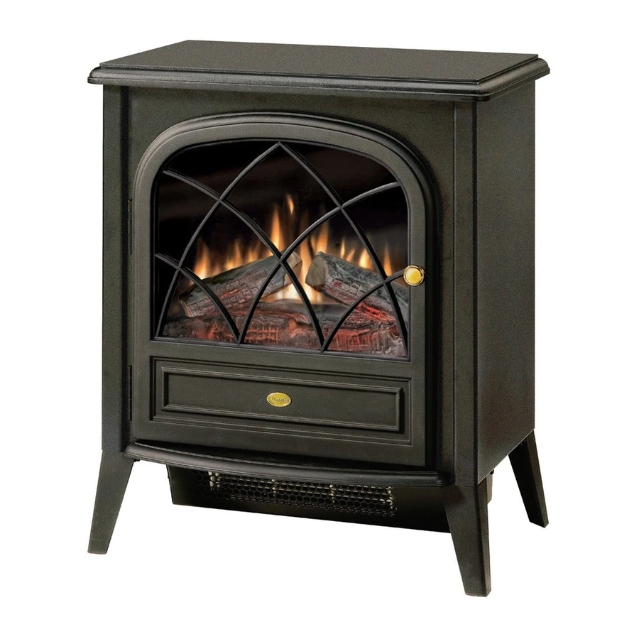
CS3311 Pictured
REV
00
01
02
PCN
DATE
~~~~
Feb 12, 07
11563
Aug 10, 09
11993
April 12, 10
7400100000rev02
Advertisement
Table of Contents

Subscribe to Our Youtube Channel
Related Manuals for Dimplex CS3311


Summary of Contents for Dimplex CS3311
- Page 1 CS4416 - MOD / to C CS2307 - MOD / to A CS3311 Pictured DATE ~~~~ Feb 12, 07 Dimplex North America Limited 11563 Aug 10, 09 1367 Industrial Road Cambridge ON Canada N1R 7G8 1-888-346-7539 www.dimplex.com 11993 April 12, 10 In keeping with our policy of continuous product development, we reserve the right to make changes without notice.
-
Page 2: Table Of Contents
Table Of Contents Page 3 Operation Page 4 Exploded Parts Diagram and Parts List Page 5 Wiring Diagram Page 6 Light Bulb Replacement Page 6 Mirror Replacement Page 6 Switch Replacement Page 7 Flicker Motor/Flicker Rod Replacement Page 8 Remote Control Replacement Page 9 Heater Assembly/Cutout Replacement Page 10... -
Page 3: Operation
Operation CAUTION: If you need to continuously reset the heater, unplug the unit and call Dimplex North America Limited at Electric Stove Manual Control 1-888-346-7539 for technical support. The manual controls for the stove are located in the upper Remote Operation left hand corner on the rear of the stove (Figure 1). -
Page 4: Exploded Parts Diagram
5. 3 Position ON/OFF Switch ..2800071100RP 14. Polished Door Knob (CS3311) ..8800340100RP 6. Cord Set ......4100090100RP Door Handle (CS4416, CS2307). -
Page 5: Wiring Diagram
Wiring Diagram... -
Page 6: Light Bulb Replacement
Light Bulb Replacement Mirror Replacement Allow at least five (5) minutes for light bulbs to cool before If the stove was operating prior to servicing allow at least touching bulbs to avoid accidental burning of skin. 10 minutes for light bulbs and heating element to cool off to avoid accidental burning of skin. -
Page 7: Flicker Motor/Flicker Rod Replacement
screws along each side; and three (3) screws at the front, 2. Remove the 11 Philips screws that attach the top panel to accessible behind the door. the stove as shown in Figure 4 (page 6). There are: four (4) screws along each side; and three (3) screws at the 3. -
Page 8: Remote Control Replacement
18. Follow steps 1 through 8 in reverse order to reassemble CAUTION: Use caution when removing the bottom pan the stove. as the Heater Assembly is attached to it and is wired to the stove. Remote Control Replacement 9. On the underside of the stove interior, disconnect the Remote Control hand held transmitters require no three (3) wires from the Terminal Block that lead to the replacement procedure however, a reinitialization procedure... -
Page 9: Heater Assembly/Cutout Replacement
Heater Assembly/Cutout Replacement the stove and connects to Heater ON/OFF Switch. If the stove was operating prior to servicing allow at least 10 minutes for light bulbs and heating element to cool off to Figure 12 Long yellow to Heater Cutout ON/OFF Switch avoid accidental burning of skin. -
Page 10: Thermostat Replacement
8. Remove the two (2) black metal stand off brackets from Figure 15 the Heater Assembly by removing the two (2) Philips screws that hold each bracket in place. Blue wire clip leading to lower section of stove 9. Remove the black metal baffle that surrounds the Heater Assembly’s Element by removing the four (4) Philips screws that hold it in place. - Page 11 Power Cord through stove and out back of stove. Figure 16 9. Feed replacement Power Cord through access at back of stove and connect wire clips to both Remote Control Receiver board and 3 Position ON/OFF Switch as shown in Figure 18. 10.
Need help?
Do you have a question about the CS3311 and is the answer not in the manual?
Questions and answers