Dimplex CS3311 Service Manual
Compact stove
Hide thumbs
Also See for CS3311:
- Parts and service manual (12 pages) ,
- Service manual (11 pages) ,
- Troubleshooting manual (2 pages)
Table of Contents
Advertisement
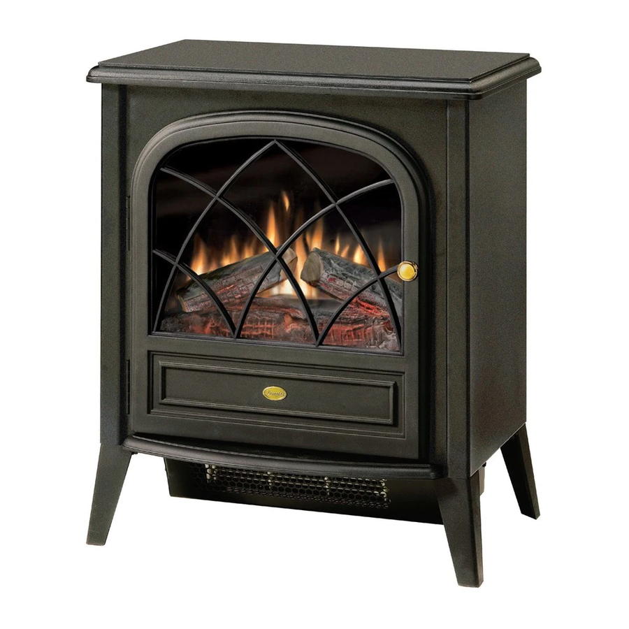
CS3311 Pictured
Dimplex North America Limited
1367 Industrial Road
Cambridge ON Canada N1R 7G8
1-888-346-7539
www.dimplex.com
In keeping with our policy of continuous product development, we reserve the right to make changes without notice.
Service Manual
Compact Stove
Model Numbers:
CS3311
CS4416
CS2307
REV
00
01
02
03
PCN
DATE
~~~~
Feb 12, 07
11563
Aug 10, 09
11993
April 12, 10
Sept 4, 12
7400100000R03
Advertisement
Table of Contents

Related Manuals for Dimplex CS3311


Summary of Contents for Dimplex CS3311
- Page 1 CS4416 CS2307 CS3311 Pictured DATE ~~~~ Feb 12, 07 11563 Aug 10, 09 Dimplex North America Limited 11993 April 12, 10 1367 Industrial Road Cambridge ON Canada N1R 7G8 1-888-346-7539 www.dimplex.com Sept 4, 12 In keeping with our policy of continuous product development, we reserve the right to make changes without notice.
-
Page 2: Table Of Contents
Table of Contents Operation ............... 3 Exploded Parts Diagram . -
Page 3: Operation
Operation unplug the unit and call Dimplex North America Limited at 1-888-346-7539 for technical support. Electric Stove Manual Control The manual controls for the stove are located in the upper Remote Operation left hand corner on the rear of the stove (Figure 1). -
Page 4: Exploded Parts Diagram
5. 3 Position Switch ....2800071100RP 14. Polished Door Knob (CS3311) ..8800340100RP 6. Power Cord .....4100090202RP Door Handle (CS4416, CS2307). -
Page 5: Wiring Diagram
Wiring Diagram... -
Page 6: Light Bulb Replacement
Light Bulb Replacement Partially Reflective Glass Replacement Allow at least five (5) minutes for light bulbs to cool before If the stove was operating prior to servicing allow at least touching bulbs to avoid accidental burning of skin. 10 minutes for light bulbs and heating element to cool off to avoid accidental burning of skin. -
Page 7: Flicker Motor/Flicker Rod Replacement
2. Remove the 11 Philips screws that attach the top panel 1. Open stove door. to the stove as shown in Figure 4. There are: four (4) 2. Remove the 11 Philips screws that attach the top panel to screws along each side; and three (3) screws at the front, the stove as shown in Figure 4 (page 6). -
Page 8: Remote Control Receiver Replacement
8. Remove four (4) Philips screws as shown in Figure 7 to 17. Connect the three (3) wires from the new motor to the release the bottom pan. Terminal Block as they originally were (refer to Figure 8). CAUTION: Use caution when removing the bottom pan 18. -
Page 9: Heater Assembly/Cutout Replacement
wire clips disconnected in step 6. Figure 12 Long yellow to Heater Cutout ON/OFF Switch 10. Follow steps 1 through 4 in revers order to reassemble the stove. Heater Assembly/Cutout Replacement Short yellow looped to If the stove was operating prior to servicing allow at least element terminals 10 minutes for light bulbs and heating element to cool off to avoid accidental burning of skin. -
Page 10: Thermostat Replacement
that hold the Heater Assembly in place from the bottom Figure 15 surface of the pan (Figure 13). 8. Remove the two (2) black metal stand off brackets from Blue wire clip leading to the Heater Assembly by removing the two (2) Philips lower section of stove screws that hold each bracket in place. - Page 11 left terminal of the Remote Control Receiver, the smooth Figure 16 edged cord connects to the center terminal of the 3 Position Switch (Figure 18). 8. Disconnect both wire clips described above and pull old Power Cord through stove and out back of stove. 9.
-
Page 12: Troubleshooting Guide
Troubleshooting Guide PROBLEM CAUSE SOLUTION General Circuit breaker trips or fuse Short in unit wiring. Trace wiring in unit. blows when unit is turned on Improper circuit current rating Additional appliances may exceed the current rating of the circuit breaker or fuse. Plug unit into another outlet or install unit on a dedicated 15 amp circuit. - Page 13 PROBLEM CAUSE SOLUTION Heater Heater is not turning off Improper operation Refer to Operation Section Defective Heater On/Off Switch Replace Heater On/Off Switch Defective Thermostat Replace Thermostat Heater is not turning on, but Improper operation Refer to Operation Section flame effect is still functioning Loose wiring Trace wiring in unit Defective Heater On/Off Switch...
Need help?
Do you have a question about the CS3311 and is the answer not in the manual?
Questions and answers
How do you clean the heater assembly on a model # CS3311 mod-C
To clean the heater assembly on a Dimplex CS3311, ensure that the exterior intake louvers and the firebox cavity are free of dirt and dust. This helps maintain proper airflow and reduces excessive noise.
This answer is automatically generated
how do I order parts from these manuals I need a flicker motor 2000210100RP for an electralog CS3311