
Related Manuals for Viessmann VITOPLEX 100?LS


Summary of Contents for Viessmann VITOPLEX 100?LS
-
Page 1: Installation Instructions
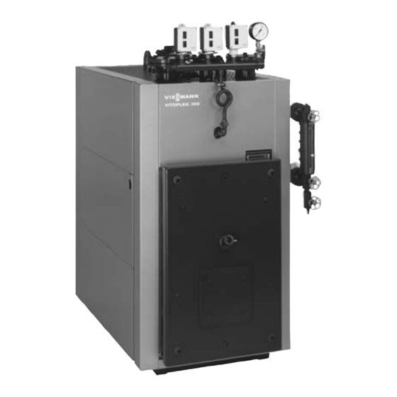
Installation instructions for heating engineers Vitoplex 100−LS Type SXD, 0.26 to 0.7 t/h Oil/gas fired boiler Steam generator up to 1 bar operating pressure VITOPLEX 100−LS Please keep safe 5592 837 GB 4/2007... -
Page 2: Safety Instructions
Safety instructions Please follow these safety instructions closely to prevent accidents and material losses. Safety regulations When using gas as fuel, also close Installation, initial start−up, inspection, the main gas shut−off valve and maintenance and repairs must only safeguard against unauthorised reopening. -
Page 3: Table Of Contents
Index Page Safety instructions ....................... . . Clearances . -
Page 4: Clearances
Clearances A Boiler 200 (100) B Burner C Sound absorbing boiler support (300) Dimensions in brackets are minimum clearances Steam output kg/h 1 200 1 300 1 400 Observe the burner length Height above the boiler Anti−vibration boiler supports Permiss. load 1 500 1 750 3 000... -
Page 5: Boiler Adjustment And Positioning
Boiler adjustment and positioning 1. Insert adjustable feet D into the For the anti−vibration boiler bottom rails. supports, the ground should be level to within 1 mm, to ensure Note even loading of the spring The adjustable feet and the sight elements. -
Page 6: Water And Steam Side Connections
Water and steam side connections ¨ Safety instruction Only open the water and steam connections after the boiler has been completely depressurised. Please note Install all pipe connections free of load and torque stresses. Thoroughly flush out the heating system, especially before connecting the boiler to an existing heating system. -
Page 7: Flue Gas Connections
Flue gas connections Vitoair installation instructions 1. Connect the flue outlet with the shortest possible run to the 10 mm chimney stack using slightly inclined flue pipes. Flue outlet for ext. ∅ 200 mm 260 and 435 kg/h ..ext. -
Page 8: Installation Of Thermal Insulation
Installation of thermal insulation Please note All components required for the assembly of the thermal insulation are included in the insulation carton. Boiler body insulation Please note A Black side towards the outside, Remove and keep safe bag D with for 700 kg/h: 2 pieces B Seal in the sensor well the type plate. -
Page 9: Front Rails And Front Insulation
Installation of thermal insulation (cont.) Front rails and front insulation Please note Front wall insulating mat; cut out if required. Secure the cutouts with spring hooks. Close the cutouts with the enclosed glass fibre strip. -
Page 10: Rear Rails And Rear Insulation
Installation of thermal insulation (cont.) Rear rails and rear insulation 4. 4. Please note Close the cutouts with the enclosed glass fibre strip. Compare the manufacturer’s details on the back of the boiler with the details on the type plate. -
Page 11: Side And Rear Panels
Installation of thermal insulation (cont.) Side and rear panels A Affix the type plate Note Request a new type plate when replacing the side panel with the type plate, quoting the serial no. -
Page 12: Front Panels And Covers
Installation of thermal insulation (cont.) Front panels and covers... -
Page 13: Installation Of Control Fittings
Installation of control fittings Note Carry out the installation in accordance with the instructions supplied with the individual equipment. See the connection and wiring diagrams regarding the electrical connection. Water level indicator and fitting assembly A Pressure switch B Pressure regulator C Pressure gauge D Fitting assembly E Water level indicator... -
Page 14: Thermostat And Covers
Installation of control fittings (cont.) Thermostat and covers A Control thermostat B Cover Fit the large cover only, if no air vent valve (accessory) is connected to the side of the boiler. C Connect the ventilation either to the connection on top of the boiler or adjacent to the water level indicator. -
Page 15: Multiple Level Electrode For Operating Pressure Up To 0.5 Bar
Installation of control fittings (cont.) Note Install the electrodes for water level control and the water level limiter in accordance with the electrode installation instructions. Match or adjust the electrodes to the switching points listed in the table. Upon request, the electrodes supplied by the boiler manufacturer can be matched to the boiler at the factory. - Page 16 Installation of control fittings (cont.) NW Lowest water level 1. Trim the electrode rods to the stated lengths. 2. Strip the electrodes after trimming them to size. Steam output kg/h Reference electrode to NW Dim. a Pump ON Dim. b Pump OFF Dim.
-
Page 17: Connection And Wiring Diagram For Operating Pressure Up To 0.5 Bar
Installation of control fittings (cont.) Connection and wiring diagram for operating pressure up to 0.5 bar NRGS 2 0 1 NRGS A Mains electrical connection H Thermostat (standby), B Burner terminals (motor, part no. 7162 267 K Feed water pump transformer, solenoid valve, L To the burner control unit photo cell, etc.) -
Page 18: Level Electrode Combination For Operating Pressure Up To 1.0 Bar
Installation of control fittings (cont.) Level electrode combination for operating pressure up to 1.0 bar Water level regulator For trimming the electrode, see page 19. - Page 19 Installation of control fittings (cont.) NW Lowest water level 4. Push test area extension B onto 1. Trim the electrode rods to the stated lengths. the central electrode rod and secure with the grub screw. 2. Strip the electrodes after trimming 5.
- Page 20 Installation of control fittings (cont.) Water level limiter...
- Page 21 Installation of control fittings (cont.) A Test area extension Steam output kg/h 260 435 700 B Locking washer Dimension a 520 565 595 NW Lowest water level...
- Page 22 Installation of control fittings (cont.) 1. Thread electrode extension D 9. Check the sealing faces on the into electrode nozzle A. flange lid. 10. Position seal ring K onto sealing 2. Tear into the test length of electrode extension D. face L of the electrode.
- Page 23 Installation of control fittings (cont.) Electrical connection Electrode connection: screened, 4−core lead, e.g. I Y(St)Y 2 × 2 × 0.8 or LIYCY 4 × 0.5 mm mS/cm. Max. length 100 m at conductivity from 10 Max. length 30 m at conductivity from 0.5 mS/cm. Max.
-
Page 24: Valve (Manual)
Installation of control fittings (cont.) T.D.S. valve (manual) 1. Unscrew the drain plug (SW 19) from the housing floor of the T.D.S. valve. 2. Insert the sampling valve. 3. Install a shut−off valve upstream. Please note Install the accessories in accordance with the installation instructions (inside their packaging). -
Page 25: Desalination Plant (Automatic)
Installation of control fittings (cont.) Desalination plant (automatic) 4. Hold the drain end of electrode rod F in a vice and saw off. 5. Shorten PTFE hose G by 12 mm, e.g. with a cable cutter. 6. Debur the start of the thread. 7. -
Page 26: Connection And Wiring Diagram For Operating Pressure Up To 1.0 Bar
Installation of control fittings (cont.) Connection and wiring diagram for operating pressure up to 1.0 bar Maximum pressure 1 −7B limiter Boiler Feed water Fault pump Maximum pressure limiter − boiler... - Page 27 Installation of control fittings (cont.) 1 −9B 10 11 12 10 11 16−11 Electrode NRG 16−11 Fault Low water level Low water level Boiler Boiler...
- Page 28 Installation of control fittings (cont.) 1 −9B 17 18 19 20 16 22 23 24 25 21 Feed water pump − OFF − Manual − Automatic 23 PE 16−36 Electrode Electrode High Boil−dry protection NRG 16−36 NRG 16−36 water level feed water pump Low water level Water level...
- Page 29 Installation of control fittings (cont.) −K2 −K3 Reset Boiler Emergency stop PE 25 26 PE −K2 −K2 −K2 −K3 −K3 −K3 28 PE 29 −K2 −K3 −K1 230V 230V 230V Mode Fault Limiter loop Fault Feed water Burner Boiler pump...
-
Page 30: Safety Connection And Checking For Leaks
Safety connection and checking for leaks 1. Fit the intermediate flange on the safety connector. Safety connection for 260 and 435 kg/h DN 65 PN 16 ..700 kg/h DN 80 PN 16 ......2. -
Page 31: Burner Installation
Burner installation Separate burner documentation. H Cut out the insulating mat in the The hole circle of the burner mounting holes, the burner burner door according to the blast mounting holes and the blast tube tube diameter. aperture comply with EN 303 1. Please note The burner may be installed directly The blast tube must protrude from... -
Page 32: Burner Adjustment
Important notes on commissioning For commissioning and adjustments, see the service instructions for boiler and burner. Viessmann Werke GmbH & Co D 35107 Allendorf Tel: +49 6452 70 0 Fax: +49 6452 70 27 80 www.viessmann.de...
Need help?
Do you have a question about the VITOPLEX 100?LS and is the answer not in the manual?
Questions and answers