Sony DSC-HX20V Service Manual
Hide thumbs
Also See for DSC-HX20V:
- Instruction manual (612 pages) ,
- User manual (274 pages) ,
- Product manual (73 pages)
Advertisement
Quick Links
DSC-HX20/HX20V/HX30/HX30V
SERVICE MANUAL
Ver. 1.2 2012.06
Internal memory
Internal memory
ON BOARD
ON BOARD
Revised-2
Replace the previously issued
SERVICE MANUAL 9-834-659-32
with this Manual.
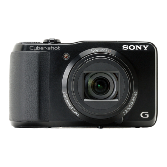
Photo: DSC-HX30V/BLACK
SERVICE NOTE (Check the following note before the service.)
– ENGLISH –
1-1. PRECAUTION ON REPLACING THE SY-325 BOARD
1-2. ADDITION OF DESTINATION DATA FILE
1-3. METHOD FOR COPYING OR ERASING THE DATA IN INTERNAL MEMORY
1-4. HOW TO WRITE DATA TO INTERNAL MEMORY
1-5. SELF-DIAGNOSIS FUNCTION
1-6. PROCESS AFTER FIXING FLASH ERROR
1-7. PRECAUTION ON REPLACING THE CABINET (BOTTOM)
1-8. CHECKING THE Wi-Fi FUNCTION
1-9. ORNAMENTAL RING A OR BARRIER ASSY REPLACING METHOD
1-10. ZOOM MOTOR GEAR BLOCK REPLACING METHOD
1-11. CAM TUBE (B) ASSY REPLACING METHOD
1-12. FINAL INSPECTION
The components identified by
Les composants identifiés par
mark 0 or dotted line with mark
une marque 0 sont critiques pour
0 are critical for safety.
la sécurité.
Replace only with part number
Ne les remplacer que par une piè-
specified.
ce portant le numéro spécifié.
DSC-HX20/HX20V/HX30/HX30V_L2
9-834-659-33
2
LEVEL
US Model
Canadian Model
AEP Model
UK Model
E Model
Australian Model
Hong Kong Model
Chinese Model
Korea Model
Japanese Model
DIGITAL STILL CAMERA
Sony Corporation
Revision History
Ver.
Date
History
1.0
2012.03
Official Release
1.1
2012.05
Revised-1
• Addition of SERVICE NOTE.
(A1 12-008)
Page 1-6, 1-11, 1-12, 1-13,
• Revision of EXPLODED VIEWS.
Page 2-3, 2-4, 2-5, 2-6,
• Correction of ACCESSORIES.
Page
2-8
• Addition of Flyer
1.2
2012.06
Revised-2
• Addition of DSC-HX20.
(A2 12-082)
Page 2, 1-5, 1-11, 2-3,
983465933.pdf
S.M. Rev.
Contents
issued
—
—
Yes
1-19
2-7
Yes
2-6
2012F08-1
© 2012.06
Published by Sony Techno Create Corporation
Advertisement

Related Manuals for Sony DSC-HX20V


Summary of Contents for Sony DSC-HX20V
-
Page 1: Revision History
0 sont critiques pour 0 are critical for safety. la sécurité. Replace only with part number Ne les remplacer que par une piè- specified. ce portant le numéro spécifié. 2012F08-1 DSC-HX20/HX20V/HX30/HX30V_L2 © 2012.06 Sony Corporation 9-834-659-33 Published by Sony Techno Create Corporation... - Page 2 Output voltage: DC 5 V, 0.5 A Approx. 18.2 Megapixels Approx. 0.4 m to 7.1 m F3.2 W F5.8 T Lens: Sony G 20× zoom lens Operating temperature: 0 °C to 40 °C HDMI HDMI (1 ft 3 3/4 inches to 23 ft 16 9 27.5...
- Page 3 ARE CRITICAL TO SAFE OPERATION. REPLACE THESE COMPO- CRITIQUES POUR LA SÉCURITÉ DE FONCTIONNEMENT. NE REM- NENTS WITH SONY PARTS WHOSE PART NUMBERS APPEAR AS PLACER CES COMPOSANTS QUE PAR DES PIÈCES SONY DONT SHOWN IN THIS MANUAL OR IN SUPPLEMENTS PUBLISHED BY LES NUMÉROS SONT DONNÉS DANS CE MANUEL OU DANS LES...
-
Page 4: Service Note
1. SERVICE NOTE – ENGLISH – 1-1. PRECAUTION ON REPLACING THE SY-325 BOARD 1-2. ADDITION OF DESTINATION DATA FILE If the Destination Data file included in the Adjust manual is old, “DESTINATION DATA WRITE” cannot be executed in some cases. DESTINATION DATA In that case, download a new Destination Data file from the TISS homepage according to the following procedure. - Page 5 – ENGLISH – 3) Search the model whose new Destination Data file you want to get on the TISS homepage. 6) Click the [File Update] button in the window. When the Destination Data file has been updated, a file with a name “Destination File For ‘model name’.zip” is registered. (Example) Destination File For DSC-WX50.zip Furthermore, the version supported by the Destination Data file is shown in the Remarks column.
- Page 6 – ENGLISH – 1-3. METHOD FOR COPYING OR ERASING THE DATA IN INTERNAL MEMORY 1-4. HOW TO WRITE DATA TO INTERNAL MEMORY The data can be copied/erased by the operations on the HOME screen. (When erasing the data, execute formatting the internal memory.) Usually, the camera has been set so as to disable the data writing from the PC to the internal memory of the camera.
- Page 7 – ENGLISH – 1-5. SELF-DIAGNOSIS FUNCTION 1-5-3. Self-diagnosis Code Table Self-diagnosis Code 1-5-2. Self-diagnosis Display 1-5-1. Self-diagnosis Function When problems occur while the unit is operating, the LCD screen shows When problems occur while the unit is operating, the self-diagnosis func- a 4-digit display consisting of an alphabet and numbers, which blinks at tion starts working, and displays on the LCD screen what to do.
- Page 8 A-1878-203-A CABINET (BOTTOM) (BLACK) A-1878-210-A CABINET (BOTTOM) (BROWN) A-1878-209-A CABINET (BOTTOM) (BROWN) A-1878-208-A CABINET (BOTTOM) (BROWN) DSC-HX30 (CH Model) DSC-HX20V (US Model) DSC-HX20V (AEP, UK, E, AUS Model) (BLACK) Serial No. Serial No. Serial No. Part No. Description Part No.
- Page 9 Ver. 1.1 2012.05 The changed portions from Ver. 1.0 are shown in blue. – ENGLISH – – JAPANESE – 1-8. CHECKING THE Wi-Fi FUNCTION Perform the following procedure to check the Wi-Fi function. Required equipment: Windows personal computer with Wi-Fi interface 1.
- Page 10 – JAPANESE – Fig. 1 Destination Ver. DSC-HX20/HX20V/HX30/HX30V_L2...
- Page 11 – JAPANESE – Destination Ver. DSC-HX20/HX20V/HX30/HX30V_L2...
- Page 12 – JAPANESE – DSC-HX20/HX20V/HX30/HX30V_L2...
- Page 13 – JAPANESE – ej el 9 qa qk w; DSC-HX20/HX20V/HX30/HX30V_L2 1-10...
- Page 14 A-1878-206-A CABINET (BOTTOM) (BLACK) A-1878-203-A CABINET (BOTTOM) (BLACK) A-1878-210-A CABINET (BOTTOM) (BROWN) A-1878-209-A CABINET (BOTTOM) (BROWN) A-1878-208-A CABINET (BOTTOM) (BROWN) DSC-HX30 (CH DSC-HX20V (US DSC-HX20V (AEP, UK, E, AUS Part No. Description Part No. Description Part No. Description A-1878-213-A CABINET (BOTTOM) (BLACK)
- Page 15 Ver. 1.1 2012.05 The changed portions from Ver. 1.0 are shown in blue. 1-9. ORNAMENTAL RING A OR BARRIER ASSY REPLACING METHOD 1-10. ZOOM MOTOR GEAR BLOCK REPLACING METHOD Removal Removal Turn on the power switch and extend the lens (TELE end). 1 Remove the screw and remove the Zoom Motor Gear Block from the Main body.
- Page 16 Ver. 1.1 2012.05 The changed portions from Ver. 1.0 are shown in blue. 1-11. CAM TUBE (B) ASSY REPLACING METHOD Turn the Naruto Gear jig clockwise to set the Main body at TELE end. Note: Turn the Naruto Gear jig to the maximum. Disengage the four Convexes on the Flexible Boards from the four Claws and pull the Flexible Boards out of the holes.
- Page 17 q; While holding the Feed-Through Cam Tube, turn the Rotary Tube Assy clockwise (approx. 5 degrees) and remove the Lens Block from qs While holding the Cam Tube (B) Assy, fully turn the Straight Tube (A) Assy clockwise (approx. 120 degrees) and remove the Feed-Through Cam Tube.
- Page 18 While holding the Straight Tube (B), fully turn the Cam Tube (A) and the Cam Tube (B) Assy counterclockwise (approx. 125 degrees) ql While holding the Straight Tube (B), fully turn the Cam Tube (B) Assy counterclockwise (approx. 3 degrees) and remove to extend the Straight Tube (B).
- Page 19 Installation 5 Align the Bayonet (wide) with the hole and install the Cam Tube (A). Install the Cam Tube (B) Assy to the Straight Tube (B) with the hole aligned with the cutout. Turn the Cam Tube (B) Assy counterclockwise (approx. 141.5 degrees) from the assembled position to align the Groove (tight) Cam Tube (A) of the Straight Tube (B) with the Groove (3rd Lens Assy Inlet) of the Cam Tube (B) Assy as shown in the figure.
- Page 20 Align the White Part with the Groove (wide) as shown in the figure and install the 1st Lens Assy to the Straight Tube (A) Assy Align the Projection (large) with the Gear as shown in the figure and install the Feed-Through Cam Tube to the Rotary Tube Assy. while inserting the three Guide keys into the three Guide grooves.
- Page 21 Align the Step with the Focus Lens Sliding Groove and install the Lens Block to the Feed-Through Cam Tube. ws Install the Rear Mirror Plate Assy and the Zoom Motor Gear Block and secure them with six screws. Engage the Projections of the Cam Tube (B) Assy and the Straight Tube (B) with the eleven Grooves of the Feed-Through Cam Tube. Note: Tighten the screws in the order of numbers in the figure below.
- Page 22 Ver. 1.1 2012.05 The changed portions from Ver. 1.0 are shown in blue. 1-12. FINAL INSPECTION 1-12-2. Inspection When Cam Tube Block Assy Or Straight Tube Lubricated Assy Is Replaced Focus check 1 Preparation 1-12-1. Confirm There is No Fault in Actual Motion/Actual Screen •...
-
Page 23: Repair Parts List
2. REPAIR PARTS LIST IDENTIFYING PARTS (ENGLISH) The components identified by mark 0 or NOTE: dotted line with mark 0 are critical for safety. Follow the disassembly in the numerical order given. Replace only with part number specified. • -XX, -X mean standardized parts, so they may have some differences from the original one. - Page 24 – ENGLISH – – JAPANESE – NOTE FOR REPAIR Cut and remove the part of gilt Cut and remove the part of gilt which comes off at the point. which comes off at the point. • Make sure that the flat cable and flexible board are not cracked (Be careful or some (Be careful or some of bent at the terminal.
- Page 25 Ver. 1.2 2012.06 The changed portions from Ver. 1.1 are shown in blue. 2-1. EXPLODED VIEWS DISASSEMBLY 2-1-1. REAR SECTION 1. Remove to numerical order ( ) in the left figure. #243 X 1 Open the HDMI lid (2) → #243 X 6 Bottom View Bottom View Left View...
- Page 26 Ver. 1.1 2012.05 The changed portions from Ver. 1.0 are shown in blue. 2-1-2. MAIN SECTION DISASSEMBLY 1. Remove to numerical order ( ) in the left figure. #243 X 3 Bottom View Top View Back View #243 #243 #243 #243 Disconnect flexible board (4) Back View...
- Page 27 Ver. 1.1 2012.05 The changed portions from Ver. 1.0 are shown in blue. DISASSEMBLY 2-1-3. FRONT SECTION 1. Remove to numerical order ( ) in the left figure. 2. The meaning of the sign in left figure is as follows. Be careful when it removes. : Solder #78 X 1 #28 X 2...
- Page 28 Ver. 1.2 2012.06 The changed portions from Ver. 1.1 are shown in blue. DISASSEMBLY 2-1-4. TOP/BTH SECTION 1. The meaning of the sign in left figure is as follows. Be careful when it removes. -X: Solder Screw #28: M1.4 X 4.0 (Tapping) (Silver) (Note 2) 3-348-998-61...
- Page 29 Ver. 1.1 2012.05 The changed portions from Ver. 1.0 are shown in blue. DISASSEMBLY 2-1-5. LENS BLOCK SECTION 1. The meaning of the sign in left figure is as follows. Be careful when it removes. -X: Solder ns: not supplied Screw #189: M1.4 X 3.5 (Tapping) #258: M1.4 X 3.5 (Tapping)
- Page 30 Ver. 1.1 2012.05 The changed portions from Ver. 1.0 are shown in blue. ACCESSORIES Ref. No. Part No. Description Ref. No. Part No. Description 1-489-282-11 AC Adaptor AC-UB10/UB12B (J) * 906 4-419-606-71 Instruction Manual (ENGLISH, SPANISH, PORTUGUESE) 1-489-282-21 AC Adaptor AC-UB10/UB10B (US, CND) * 906 4-419-606-81 Instruction Manual (ENGLISH, ARABIC, PERSIAN)
- Page 31 3. ASSEMBLY Assembly-1: Installation Cautions of the Rear Cover Assy. Assembly-3: Installation Cautions of the RL-129 Board. Be sure to install the Rear Cover Assy with Marking RL-129 Board (Adjust the position) the strobe pulled out. Rotary plate strobe Cabinet (Upper) Assy Rear Cover Assy Adjust the position Assembly-4: Precaution During of ST block installation.
- Page 32 NOTE The wireless LAN connection settings have been initialized and the MAC address has also been modifi ed during this repair. Make settings again for connection to devices as needed. For details of settings, refer to the Instruction Manual.
- Page 33 注意 因為修理原因,無線 LAN 的連接設定已初始 化。 此外,MAC 地址也已變更。 請務必要再度為所有通訊裝置進⾏起始設 定。 關於進⾏設定的詳細資訊,請參考 “使⽤說明書” 。...
- Page 34 참고 이 복 구 가 수 행 되 는 동 안 무 선 LAN 연결 설정이 초기화되었고 MAC 주소가 수정되었습니다 . 필요에 따라 장치에 대한 연결을 다시 설정하십시오 . 설정에 대한 자세한 내용은 사용 설명서를 참조하십시오 .
Need help?
Do you have a question about the DSC-HX20V and is the answer not in the manual?
Questions and answers