
Related Manuals for Fortinet FortiGate 400


Summary of Contents for Fortinet FortiGate 400
-
Page 1: Configuration Guide
Installation and FortiGate 400 Configuration Guide CONSOLE 4 / HA Enter FortiGate User Manual Volume 1 Version 2.50 MR2 18 August 2003... - Page 2 CAUTION: RISK OF EXPLOSION IF BATTERY IS REPLACED BY AN INCORRECT TYPE. DISPOSE OF USED BATTERIES ACCORDING TO THE INSTRUCTIONS. For technical support, please visit http://www.fortinet.com. Send information about errors or omissions in this document or any Fortinet technical documentation to techdoc@fortinet.com.
-
Page 3: Table Of Contents
Logging and Reporting... 24 About this document ... 25 Document conventions ... 26 Fortinet documentation ... 27 Comments on Fortinet technical documentation... 27 Customer service and technical support... 28 Getting started ... 29 Package contents ... 30 Mounting ... 30 Powering on ... - Page 4 Reconnecting to the web-based manager ... 62 Using the front control buttons and LCD... 63 Using the command line interface... 63 Changing to Transparent mode ... 63 Configuring the Transparent mode management IP address ... 64 Configure the Transparent mode default gateway... 64 Fortinet Inc.
- Page 5 Completing the configuration ... 64 Setting the date and time ... 64 Enabling antivirus protection... 64 Registering your FortiGate... 65 Configuring virus and attack definition updates ... 65 Connecting the FortiGate unit to your networks... 65 Transparent mode configuration examples... 66 Default routes and static routes ...
- Page 6 Manually updating antivirus and attack definitions... 119 Configuring push updates ... 119 Push updates through a NAT device ... 120 Scheduled updates through a proxy server ... 124 Registering FortiGate units ... 125 FortiCare Service Contracts... 125 Registering the FortiGate unit ... 126 Fortinet Inc.
- Page 7 Updating registration information ... 128 Recovering a lost Fortinet support password... 128 Viewing the list of registered FortiGate units ... 128 Registering a new FortiGate unit ... 129 Adding or changing a FortiCare Support Contract number... 129 Changing your Fortinet support password ... 130 Changing your contact information or security question ...
- Page 8 Policy matching in detail ... 177 Changing the order of policies in a policy list... 178 Enabling and disabling policies... 178 Addresses ... 179 Adding addresses ... 179 Editing addresses ... 180 Deleting addresses ... 180 Organizing addresses into address groups ... 181 Fortinet Inc.
- Page 9 Services ... 182 Predefined services ... 182 Providing access to custom services ... 184 Grouping services ... 185 Schedules ... 186 Creating one-time schedules ... 186 Creating recurring schedules ... 187 Adding a schedule to a policy ... 188 Virtual IPs... 188 Adding static NAT virtual IPs ...
- Page 10 Configuring a Windows XP client for PPTP ... 240 Configuring L2TP ... 241 Configuring the FortiGate unit as a L2TP gateway ... 242 Configuring a Windows 2000 client for L2TP... 245 Configuring a Windows XP client for L2TP ... 246 Fortinet Inc.
- Page 11 Network Intrusion Detection System (NIDS) ... 249 Detecting attacks ... 249 Selecting the interfaces to monitor... 250 Disabling the NIDS... 250 Configuring checksum verification ... 250 Viewing the signature list ... 251 Viewing attack descriptions... 251 Enabling and disabling NIDS attack signatures ... 252 Adding user-defined signatures ...
- Page 12 Downloading a log file to the management computer... 291 Deleting all messages in an active log... 291 Deleting a saved log file... 292 Configuring alert email ... 292 Adding alert email addresses... 292 Testing alert email... 293 Enabling alert email ... 293 Fortinet Inc.
- Page 13 Contents Glossary ... 295 Index ... 299 FortiGate-400 Installation and Configuration Guide...
- Page 14 Contents Fortinet Inc.
-
Page 15: Introduction
• • Your FortiGate Antivirus Firewall employs Fortinet’s Accelerated Behavior and Content Analysis System (ABACAS™) technology, which leverages breakthroughs in chip design, networking, security, and content analysis. The unique ASIC-based architecture analyzes content and behavior in real-time, enabling key applications to be deployed right at the network edge where they are most effective at protecting your networks. -
Page 16: Web Content Filtering
PKZip format, detect viruses in e-mail that has been encoded using uuencode format, detect viruses in e-mail that has been encoded using MIME encoding, log all actions taken while scanning. Introduction Fortinet Inc. -
Page 17: Firewall
Introduction You can configure Email blocking to tag email from all or some senders within organizations that are known to send spam email. To prevent unintentional tagging of email from legitimate senders, you can add sender address patterns to an exempt list that overrides the email block and banned word lists. -
Page 18: Transparent Mode
To notify system administrators of the attack, the NIDS records the attack and any suspicious traffic to the attack log and can be configured to send alert emails. Fortinet updates NIDS attack definitions periodically. You can download and install updated attack definitions manually, or you can configure the FortiGate to automatically check for and download attack definition updates. -
Page 19: Vpn
• • High availability High Availability (HA) provides fail-over between two or more FortiGate units. Fortinet achieves HA through the use of redundant hardware: matching FortiGate models running in NAT/Route mode. You can configure the FortiGate units for either active-passive (A-P) or active-active (A-A) HA. -
Page 20: Secure Installation, Configuration, And Management
Once a satisfactory configuration has been established, it can be downloaded and saved. The saved configuration can be restored at any time. Figure 1: The FortiGate web-based manager and setup wizard Introduction Fortinet Inc. -
Page 21: Command Line Interface
Introduction Command line interface You can access the FortiGate command line interface (CLI) by connecting a management computer serial port to the FortiGate RS-232 serial Console connector. You can also use Telnet or a secure SSH connection to connect to the CLI from any network connected to the FortiGate, including the Internet. -
Page 22: What's New In Version 2.50
System > Update page displays more information about the current update status. See “Updating antivirus and attack definitions” on page Direct connection to the Fortinet tech support web page from the web-based manager. You can register your FortiGate unit and get access to other technical support resources. See “Registering FortiGate units”... -
Page 23: Replacement Messages
Introduction • • • • Replacement messages You can customize messages sent by the FortiGate unit: • • • • Firewall • • • Users and authentication • See the FortiGate VPN Guide for a complete description of FortiGate VPN functionality. -
Page 24: Nids
Log message levels: Emergency, Alert, critical, error, Warning, notification, information Log level policies Traffic log filter New antivirus, web filter, and email filter logs Alert email supports authentication Suppress email flooding Extended WebTrends support for graphing activity Introduction Fortinet Inc. -
Page 25: About This Document
Introduction About this document This installation and configuration guide describes how to install and configure the FortiGate-400. This document contains the following information: • • • • • • • • • • • • • • • • • •... -
Page 26: Document Conventions
You can enter set system opmode nat or set system opmode transparent square brackets [ ] to indicate that a keyword is optional For example: get firewall ipmacbinding [dhcpipmac] You can enter get firewall ipmacbinding or get firewall ipmacbinding dhcpipmac Introduction Fortinet Inc. -
Page 27: Fortinet Documentation
The FortiGate online help also contains procedures for using the FortiGate web-based manager to configure and manage your FortiGate unit. Comments on Fortinet technical documentation You can send information about errors or omissions in this document or any Fortinet technical documentation to techdoc@fortinet.com. FortiGate-400 Installation and Configuration Guide Volume 1: FortiGate Installation and Configuration Guide Describes installation and basic configuration for the FortiGate unit. -
Page 28: Customer Service And Technical Support
Fortinet technical support web site at http://support.fortinet.com. You can also register FortiGate Antivirus Firewalls from http://support.fortinet.com and modify your registration information at any time. Fortinet email support is available from the following addresses: amer_support@fortinet.com For customers in the United States, Canada, Mexico, Latin... -
Page 29: Getting Started
FortiGate-400 Installation and Configuration Guide Version 2.50 MR2 Getting started This chapter describes unpacking, setting up, and powering on your FortiGate Antivirus Firewall. When you have completed the procedures in this chapter, you can proceed to one of the following: •... -
Page 30: Package Contents
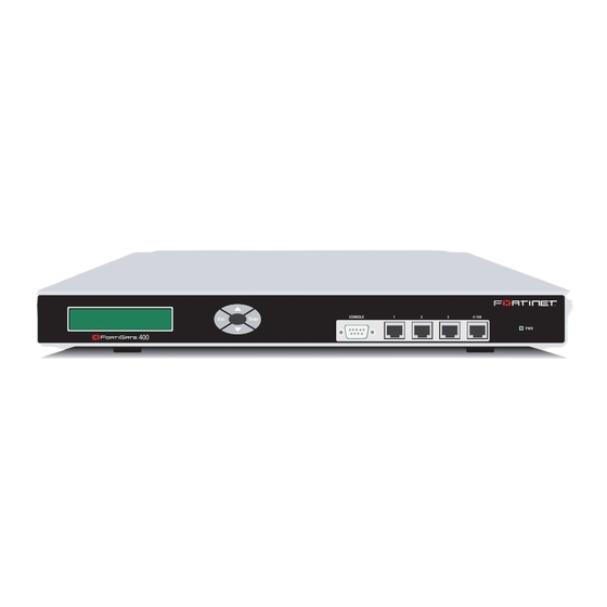
Getting started Ethernet Cables: Orange - Crossover Grey - Straight-through Null-Modem Cable (RS-232) Power Cable FortiGate-400 Enter CONSOLE 4 / HA QuickStart Guide Copyright 2003 Fortinet Incorporated. All rights reserved. Trademarks Products mentioned in this document are trademarks. Documentation Fortinet Inc. -
Page 31: Power Requirements
Getting started Power requirements • • • • Environmental specifications • • • Powering on To power on the FortiGate-400 unit: Make sure that the power switch on the back is turned off. Connect the power cable to the power connection on the back of the FortiGate unit. Connect the power cable to a power outlet. -
Page 32: Connecting To The Web-Based Manager
The Register Now window is displayed. Use the information on this window to register your FortiGate unit so that Fortinet can contact you for firmware updates. You must also register to receive updates to the FortiGate virus and attack definitions. -
Page 33: Connecting To The Command Line Interface (Cli)
Getting started Connecting to the command line interface (CLI) As an alternative to the web-based manager, you can install and configure the FortiGate unit using the CLI. Configuration changes made with the CLI are effective immediately without the need to reset the firewall or interrupt service. To connect to the FortiGate CLI, you need: •... -
Page 34: Factory Default Nat/Route Mode Network Configuration
Secondary DNS Server: Management Access: Netmask: Management Access: Table 2. This configuration allows you to Table 2 HTTPS User name: admin Password: (none) 192.168.1.99 255.255.255.0 HTTPS, Ping 192.168.100.99 255.255.255.0 192.168.100.1 207.194.200.1 207.194.200.129 Ping 0.0.0.0 0.0.0.0 HTTPS, Ping Getting started Fortinet Inc. -
Page 35: Factory Default Transparent Mode Network Configuration
Getting started Table 2: Factory default NAT/Route mode network configuration (Continued) Interface 4/HA Factory default Transparent mode network configuration If you switch the FortiGate unit to Transparent mode, it has the default network configuration listed in Table 3: Factory default Transparent mode network configuration Administrator account Management IP... -
Page 36: Factory Default Content Profiles
Log Traffic is not selected. This policy does not record messages to the traffic log for the traffic processed by this policy. You can configure FortiGate logging and select Log Traffic to record all connections through the firewall that are accepted by this policy. Getting started Fortinet Inc. - Page 37 Getting started Strict content profile Use the strict content profile to apply maximum content protection to HTTP, FTP, IMAP, POP3, and SMTP content traffic. You would not use the strict content profile under normal circumstances, but it is available if you are having extreme problems with viruses and require maximum content screening protection.
- Page 38 Web Exempt List Email Block List Email Exempt List Email Content Block Oversized File/Email Block Pass Fragmented Emails Getting started HTTP IMAP POP3 pass pass pass pass HTTP IMAP POP3 pass pass pass pass SMTP pass SMTP pass Fortinet Inc.
-
Page 39: Planning Your Fortigate Configuration
Getting started Planning your FortiGate configuration Before beginning to configure the FortiGate unit, you need to plan how to integrate the unit into your network. Among other things, you have to decide whether or not the unit will be visible to the network, which firewall functions it will provide, and how it will control the traffic flowing between its interfaces. -
Page 40: Nat/Route Mode With Multiple External Network Connections
Interface 1 is the interface to the internal network. Interface 2 is the default interface to the external network (usually the Internet). Interface 3 is the interface to the DMZ network. Interface 4/HA is the redundant interface to the external network. Getting started Fortinet Inc. -
Page 41: Transparent Mode
Getting started Transparent mode In Transparent mode, the FortiGate unit is invisible to the network. Similar to a network bridge, all of FortiGate interfaces must be on the same subnet. You only have to configure a management IP address so that you can make configuration changes. The management IP address is also used for antivirus and attack definition updates. -
Page 42: Fortigate Model Maximum Values Matrix
50000 50000 3000 6000 10000 10000 1000 1000 1000 1000 2000 2000 5000 5000 1500 3000 5000 5000 1024* 1024* 2048* 2048* Getting started 3000 3600 50000 50000 10000 10000 1000 1000 5000 5000 5000 5000 8192* 8192* Fortinet Inc. -
Page 43: Next Steps
Getting started Table 9: FortiGate maximum values matrix IP pool RADIUS server File pattern PPTP user L2TP user URL block no limit no limit no limit no limit no limit no limit no limit no limit no limit no limit no limit Content block no limit no limit no limit no limit no limit no limit no limit no limit no limit no limit no limit Exempt URL... - Page 44 Next steps Getting started Fortinet Inc.
-
Page 45: Nat/Route Mode Installation
FortiGate-400 Installation and Configuration Guide Version 2.50 MR2 NAT/Route mode installation This chapter describes how to install your FortiGate unit in NAT/Route mode. To install your FortiGate unit in Transparent mode, see page page This chapter describes: • • • •... -
Page 46: Using The Setup Wizard
IMAP server, or FTP server installed on an internal network, add the IP addresses of the servers here. Table 10 on page 45 “Completing the configuration” on page NAT/Route mode installation _____._____._____._____ _____._____._____._____ _____._____._____._____ _____._____._____._____ _____._____._____._____ _____._____._____._____ _____._____._____._____ to fill in the wizard fields. Fortinet Inc. -
Page 47: Using The Front Control Buttons And Lcd
NAT/Route mode installation Using the front control buttons and LCD As an alternative to the setup wizard, use the information that you recorded in Table 10 on page 45 displayed on the LCD, use the front control buttons and LCD: Press Enter three times to configure the PORT1 IP address. - Page 48 Set the default route to the Default Gateway IP address. set system route number <route_no> dst 0.0.0.0 0.0.0.0 gw1 <gateway_ip> Example set system route number 0 dst 0.0.0.0 0.0.0.0 gw1 204.23.1.2 Table 10 on page Table 10 on page NAT/Route mode installation Fortinet Inc.
-
Page 49: Connecting The Fortigate Unit To Your Networks
NAT/Route mode installation Connecting the FortiGate unit to your networks When you have completed the initial configuration, you can connect the FortiGate unit between your internal network and the Internet. The FortiGate-400 has four 10/100Base-TX connectors that can be connected to up to four different networks. -
Page 50: Configuring Your Network
Use the following procedure to configure interface 3 to connect to a network: Log into the web-based manager. Go to System > Network > Interface. Choose port3 and select Modify Change the IP address and Netmask as required. Select Apply. NAT/Route mode installation Fortinet Inc. -
Page 51: Configuring Interface 4/Ha
After purchasing and installing a new FortiGate unit, you can register the unit by going to System > Update > Support, or using a web browser to connect to http://support.fortinet.com and selecting Product Registration. Registration consists of entering your contact information and the serial numbers of the FortiGate units you or your organization have purchased. -
Page 52: Configuring Virus And Attack Definition Updates
115. 138) and FortiGate firewall configuration (see 169). Configuring Ping servers Destination based routing examples Policy routing examples Firewall policy example NAT/Route mode installation “Updating antivirus and attack Figure 8). In this “Configuring routing” on “Firewall configuration” on Fortinet Inc. -
Page 53: Configuring Ping Servers
NAT/Route mode installation Figure 8: Example multiple Internet connection configuration Configuring Ping servers Use the following procedure to make Gateway 1 the ping server for port2 and Gateway 2 the ping server for port3. Go to System > Network > Interface. For port2, select Modify •... -
Page 54: Destination Based Routing Examples
Load sharing and primary and secondary connections Destination IP: 0.0.0.0 Mask: 0.0.0.0 Gateway #1: 1.1.1.1 Gateway #2: 2.2.2.1 Device #1: port2 Device #2: port3 Select OK. Gateway #1 0.0.0.0 1.1.1.1 NAT/Route mode installation Device #1 Gateway #2 Device #2 port2 2.2.2.1 port3 Fortinet Inc. -
Page 55: Load Sharing
NAT/Route mode installation Load sharing You can also configure destination routing to direct traffic through both gateways at the same time. If users on your internal network connect to the networks of ISP1 and ISP2, you can add routes for each of these destinations. Each route can include a backup destination to the network of the other ISP. - Page 56 Type a number in the Move to field to move this route to the bottom of the list. If there are only 3 routes, type 3. Select OK. Gateway #1 255.255.255.0 1.1.1.1 255.255.255.0 2.2.2.1 0.0.0.0 1.1.1.1 NAT/Route mode installation Table Device #1 Gateway #2 Device #2 port2 2.2.2.1 port3 port3 1.1.1.1 port2 port2 2.2.2.1 port3 Fortinet Inc.
-
Page 57: Policy Routing Examples
NAT/Route mode installation Policy routing examples Policy routing can be added to increase the control you have over how packets are routed. Policy routing works on top of destination-based routing. This means you should configure destination-based routing first and then build policy routing on top to increase the control provided by destination-based routing. -
Page 58: Firewall Policy Example
Destination Schedule Service Action Select OK to save your changes. shows a FortiGate unit connected to the Internet using its port2 “Default firewall configuration” on page 0.0.0.0 0.0.0.0 Port1_All Port3_All Always Accept Select NAT. NAT/Route mode installation 170. Fortinet Inc. - Page 59 NAT/Route mode installation Adding more firewall policies In most cases your firewall configuration includes more than just the default policy. However, the basic premise of creating redundant policies applies even as the firewall configuration becomes more complex. To configure the FortiGate unit to use multiple Internet connections you must add duplicate policies for connections between the internal network and both interfaces connected to the Internet.
- Page 60 Configuration example: Multiple connections to the Internet NAT/Route mode installation Fortinet Inc.
-
Page 61: Transparent Mode Installation
FortiGate-400 Installation and Configuration Guide Version 2.50 MR2 Transparent mode installation This chapter describes how to install your FortiGate unit in Transparent mode. If you want to install the FortiGate unit in NAT/Route mode, see installation” on page This chapter describes: •... -
Page 62: Using The Setup Wizard
If you connect to the management interface through a router, make sure that you have added a default gateway for that router to the management IP default gateway field. Transparent mode installation Table 14 on page 61 to fill in the wizard fields. Fortinet Inc. -
Page 63: Using The Front Control Buttons And Lcd
Transparent mode installation Using the front control buttons and LCD This procedure describes how to use the control buttons and LCD to configure Transparent mode IP addresses. Use the information that you recorded in page 61 use the front control buttons and LCD: Press Enter three times to configure the management interface IP address. -
Page 64: Configuring The Transparent Mode Management Ip Address
Select Anti-Virus & Web filter to enable antivirus protection for this policy. Select the Scan Content Profile. Select OK to save your changes. Table 14 on page 61. Enter: 157. to edit this policy. Transparent mode installation Table 14 on page “Setting system date and time” on Fortinet Inc. -
Page 65: Registering Your Fortigate
After purchasing and installing a new FortiGate unit, you can register the unit by going to System > Update > Support, or using a web browser to connect to http://support.fortinet.com and selecting Product Registration. Registration consists of entering your contact information and the serial numbers of the FortiGate units you or your organization have purchased. -
Page 66: Transparent Mode Configuration Examples
If, however, the network topology is more complex, you may be required to enter one or more static routes in addition to the default route. the management computer, The FortiResponse Distribution Network (FDN), a DNS server. Transparent mode installation Fortinet Inc. -
Page 67: Default Routes And Static Routes
Transparent mode installation This section describes: • • • • Default routes and static routes To create a route to a destination, you need to define an IP prefix which consists of an IP network address and a corresponding netmask value. A default route matches any prefix and forwards traffic to the next hop router (otherwise known as the default gateway). -
Page 68: General Configuration Steps
Figure 10: Default route to an external network General configuration steps Set the FortiGate unit to operate in Transparent mode. Configure the Management IP address and Netmask of the FortiGate unit. Configure the default route to the external network. Transparent mode installation Fortinet Inc. -
Page 69: Example Static Route To An External Destination
• • CLI configuration steps To configure the Fortinet basic settings and a default route using the CLI: Change the system to operate in Transparent Mode. Add the Management IP address and Netmask. Add the default route to the external network. - Page 70 Set the FortiGate unit to operate in Transparent mode. Configure the Management IP address and Netmask of the FortiGate unit. Configure the static route to the FortiResponse server. Configure the default route to the external network. Transparent mode installation Fortinet Inc.
- Page 71 • • CLI configuration steps To configure the Fortinet basic settings and a static route using the CLI: Set the system to operate in Transparent Mode. Add the Management IP address and Netmask. Add the static route to the primary FortiResponse server.
-
Page 72: Example Static Route To An Internal Destination
Configure the Management IP address and Netmask of the FortiGate unit. Configure the static route to the management computer on the internal network. Configure the default route to the external network. shows a FortiGate unit where the FDN is located on an external subnet and Transparent mode installation Fortinet Inc. - Page 73 Transparent mode installation Web-based manager example configuration steps To configure the FortiGate basic settings, a static route, and a default route using the web-based manager: Go to System > Status. • • • Go to System > Network > Management. •...
- Page 74 Transparent mode configuration examples Transparent mode installation Fortinet Inc.
-
Page 75: High Availability
FortiGate-400 Installation and Configuration Guide Version 2.50 MR2 High availability Fortinet achieves high availability (HA) using redundant hardware and the FortiGate Clustering Protocol (FGCP). The FortiGate units in the HA cluster enforce the same overall security policy and share the same configuration settings. You can add up to 32 FortiGate units to an HA cluster. -
Page 76: Active-Active Ha
Distributes traffic to units in a cluster based on the Source IP and Destination IP of the packet. Distributes traffic to units in a cluster based on the Source IP, Source Port, Destination IP, and Destination port of the packet. High availability Fortinet Inc. -
Page 77: Ha In Nat/Route Mode
High availability During startup the members of the HA cluster negotiate to select the primary unit. The primary unit allows other FortiGate units to join the HA cluster as subordinate units and assigns each subordinate unit a priority. The FortiGate units in the HA cluster communicate status and session information using their HA interfaces. -
Page 78: Configuring The Ha Cluster
To allow Telnet connections to the CLI through this interface. Telnet connections are not secure and can be intercepted by a third party. to connect the HA cluster to your network first. High availability “Configuring the HA “Connecting Fortinet Inc. - Page 79 High availability Select the HA mode. Select Active-Passive mode to create an Active-Passive HA cluster, in which one FortiGate unit in the HA cluster is actively processing all connections and the others are passively monitoring the status and remaining synchronized with the active FortiGate unit.
-
Page 80: Connecting The Ha Cluster To Your Network
For this reason, the connection between the HA ports of all of the FortiGate units in the cluster must be well maintained. An interruption of this communication can cause unpredictable results. Switches are recommended for performance reasons. network”. High availability “Connecting the HA Fortinet Inc. - Page 81 High availability The network equipment to use and the procedure to follow are the same, whether you are configuring the FortiGate units for active-active HA or active-passive HA. To connect the FortiGate units to your network: Connect port 1 of each FortiGate unit to a switch or hub connected to your internal network.
-
Page 82: Starting The Ha Cluster
Configuring the HA cluster Connecting the HA cluster to your network Starting the HA cluster “Transparent mode installation” on page 61 “Configuring the HA interface and HA IP High availability to log into and to install and address”. Fortinet Inc. -
Page 83: Configuring The Ha Cluster
High availability HTTPS PING HTTP SNMP TELNET Change the HA IP address and Netmask as required. Optionally configure management access for other interfaces. Select Apply. Now that you have configured the HA interfaces, proceed to cluster”. Configuring the HA cluster Use the following procedure to configure each FortiGate unit for HA before connecting the HA cluster to your network. - Page 84 Load balancing according to IP address and port. If the FortiGate units are connected using switches, select IP Port to distribute traffic to units in a cluster based on the Source IP, Source Port, Destination IP, and Destination port of the packet. High availability Fortinet Inc.
-
Page 85: Connecting The Ha Cluster To Your Network
High availability Figure 15: Sample active-passive HA configuration Repeat this procedure to add each FortiGate unit in the HA cluster. When you have configured all of the FortiGate units, proceed to cluster to your Connecting the HA cluster to your network To connect the HA cluster to your network you must connect all matching interfaces in the cluster to the same hub or switch. -
Page 86: Starting The Ha Cluster
Viewing the status of cluster members Monitoring cluster members Monitoring cluster sessions Viewing and managing cluster log messages Managing individual cluster units Synchronizing the cluster configuration Returning to standalone configuration Replacing a FortiGate unit after fail-over High availability to log into and Fortinet Inc. -
Page 87: Monitoring Cluster Members
High availability Figure 16: Example cluster members list Monitoring cluster members To monitor health information for each cluster member. Connect to the cluster and log into the web-based manager. Go to System > Status > Monitor. CPU, Memory Status, and Hard disk status is displayed for each cluster member. The primary unit is identified as Local and the other units in the cluster are listed by serial number. -
Page 88: Monitoring Cluster Sessions
“Downloading a log file to the management computer” on page messages in an active log” on page page 292) “Viewing logs saved to memory” on 291, 291, and “Deleting a saved log file” on High availability 112. 290) “Deleting all Fortinet Inc. -
Page 89: Managing Individual Cluster Units
High availability Note: Note you can view and manage log messages for all cluster members. However, from the primary unit you can only configure logging for the primary unit. To configure logging for other units in the cluster you must manage individual cluster units. Managing individual cluster units You can manage individual cluster units by connecting to each unit’s HA interface using either the web-based manager or the CLI. -
Page 90: Returning To Standalone Configuration
Synchronize CA certificates added to the primary unit. Synchronize local certificates added to the primary unit. Synchronize all of the above. “Managing individual cluster units” on page for all of the subordinate units in the HA cluster. High availability Fortinet Inc. -
Page 91: Advanced Ha Options
High availability Advanced HA options The following advanced HA options are available from the FortiGate CLI: • • Selecting a FortiGate unit to a permanent primary unit In a typical FortiGate cluster configuration, the primary unit selection process is automatic. The primary unit can be different each time the cluster starts up. In addition the unit functioning as the primary unit can change from time to time (for example, if the current primary unit restarts, one of the other units in the cluster replaces it as the primary unit). -
Page 92: Configuring Weighted-Round-Robin Weights
The first connection is processed by the primary unit The next three connections are processed by the first subordinate unit The next three connections are processed by the second subordinate unit High availability Fortinet Inc. -
Page 93: System Status
FortiGate-400 Installation and Configuration Guide Version 2.50 MR2 System status You can connect to the web-based manager and go to System > Status to view the current status of your FortiGate unit. The status information that is displayed includes the current firmware version, the current virus and attack definitions, and the FortiGate unit serial number. -
Page 94: Changing The Fortigate Host Name
The new host name appears on the System Status page and is added to the SNMP System Name. Changing the FortiGate firmware After you download a FortiGate firmware image from Fortinet, you can use the procedures in Table 1: Firmware upgrade procedures... -
Page 95: Upgrade To A New Firmware Version
System status Upgrade to a new firmware version Use the following procedures to upgrade your FortiGate to a newer firmware version. Upgrading the firmware using the web-based manager Note: Installing firmware replaces your current antivirus and attack definitions with the definitions included with the firmware release that you are installing. -
Page 96: Revert To A Previous Firmware Version
Where <name_str> is the name of the firmware image file on the TFTP server and <tftp_ip> is the IP address of the TFTP server. For example, if the firmware image file name is FGT_300-v250-build045-FORTINET.out and the IP address of the TFTP server is 192.168.1.168, enter: execute restore image FGT_300-v250-build045-FORTINET.out... - Page 97 System status Note: Installing firmware replaces your current antivirus and attack definitions with the definitions included with the firmware release that you are installing. When you have installed new firmware, use the procedure page 119 Copy the firmware image file to your management computer. Login to the FortiGate web-based manager as the admin administrative user.
- Page 98 Where <name_str> is the name of the firmware image file on the TFTP server and <tftp_ip> is the IP address of the TFTP server. For example, if the firmware image file name is FGT_300-v250-build045-FORTINET.out and the IP address of the TFTP server is 192.168.1.168, enter: execute restore image FGT_300-v250-build045-FORTINET.out...
-
Page 99: Install A Firmware Image From A System Reboot Using The Cli
System status To confirm that the antivirus and attack definitions have been updated, enter the following command to display the antivirus engine, virus and attack definitions version, contract expiry, and last update attempt information. get system objver Install a firmware image from a system reboot using the CLI This procedure installs a specified firmware image and resets the FortiGate unit to default settings. - Page 100 Get firmware image from TFTP server. [F]: Format boot device. [B]: Boot with backup firmware and set as default. [Q]: Quit menu and continue to boot with default firmware. [H]: Display this list of options. Enter G,F,B,Q,or H: System status command. execute reboot Fortinet Inc.
-
Page 101: Test A New Firmware Image Before Installing It
System status Enter the firmware image file name and press Enter. The TFTP server uploads the firmware image file to the FortiGate unit and messages similar to the following appear. • • The FortiGate unit installs the new firmware image and restarts. The installation might take a few minutes to complete. - Page 102 FortiGate unit running v3.x BIOS [G]: Get firmware image from TFTP server. [F]: Format boot device. [Q]: Quit menu and continue to boot with default firmware. [H]: Display this list of options. Enter G,F,Q,or H: System status command. execute reboot Fortinet Inc.
-
Page 103: Installing And Using A Backup Firmware Image
System status Note: The local IP address is only used to download the firmware image. After the firmware is installed the address of this interface is changed back to the default IP address for this interface. The following message appears: Enter File Name [image.out]: Enter the firmware image file name and press Enter. - Page 104 Get firmware image from TFTP server. Format boot device. Boot with backup firmware and set as default. Quit menu and continue to boot with default firmware. Display this list of options. System status command. execute reboot Fortinet Inc.
- Page 105 System status Switching to the backup firmware image Use this procedure to switch your FortiGate unit to operating with a backup firmware image that you have previous installed. When you switch the FortiGate unit to the backup firmware image, the FortiGate unit operates using the configuration that was saved with that firmware image.
-
Page 106: Manual Virus Definition Updates
System > Update and selecting Update Now. Download the latest antivirus definitions update file from Fortinet and copy it to the computer that you use to connect to the web-based manager. -
Page 107: Manual Attack Definition Updates
System > Update and selecting Update Now. Download the latest attack definitions update file from Fortinet and copy it to the computer that you use to connect to the web-based manager. -
Page 108: Backing Up System Settings
The FortiGate unit restarts with the configuration that it had when it was first powered Reconnect to the web-based manager and review the system configuration to confirm that it has been reset to the default settings. To restore your system settings, see “Restoring system settings” on page System status 108. Fortinet Inc. -
Page 109: Changing To Transparent Mode
System status Changing to Transparent mode Use the following procedure to switch the FortiGate unit from NAT/Route mode to Transparent mode. When the FortiGate unit has changed to Transparent mode its configuration resets to Transparent mode factory defaults. Go to System > Status. Select Change to Transparent Mode. -
Page 110: Shutting Down The Fortigate Unit
If CPU and memory use is high, the FortiGate unit is performing near its full capacity. Placing additional demands on the system could lead to traffic processing delays. Viewing CPU and memory status Viewing sessions and network status Viewing virus and intrusions status System status Fortinet Inc. -
Page 111: Viewing Sessions And Network Status
System status Figure 1: CPU and memory status monitor CPU and memory intensive processes such as encrypting and decrypting IPSec VPN traffic, virus scanning, and processing high levels of network traffic containing small packets will increase CPU and memory usage. Go to System >... -
Page 112: Viewing Virus And Intrusions Status
Virus and intrusions status is displayed. The display includes bar graphs of the number viruses and intrusions detected per hour as well as line graphs of the number of viruses and intrusions detected for the last 20 hours. System status Fortinet Inc. -
Page 113: Session List
System status Figure 3: Sessions and network status monitor Set the automatic refresh interval and select Go to control how often the web-based manager updates the display. More frequent updates use system resources and increase network traffic. However, this only occurs when you are viewing the display using the web-based manager. The line graph scales are shown on the upper right corner of the graph. - Page 114 To IP To Port Expire Clear Figure 4: Example session list The destination IP address of the connection. The destination port of the connection. The time, in seconds, before the connection expires. Stop an active communication session. System status Fortinet Inc.
-
Page 115: Virus And Attack Definitions Updates And Registration
Network (FDN) to update the antivirus and attack definitions and antivirus engine. You have the following update options: • • • To receive scheduled updates and push updates, you must register the FortiGate unit on the Fortinet Support web page. This chapter describes: • • • •... -
Page 116: Connecting To The Fortiresponse Distribution Network
Adding an override server Manually updating antivirus and attack definitions Configuring push updates Push updates through a NAT device Scheduled updates through a proxy server 117. 119. Virus and attack definitions updates and registration “Configuring push updates” on “Configuring Fortinet Inc. -
Page 117: Configuring Scheduled Updates
Virus and attack definitions updates and registration To make sure the FortiGate unit can connect to the FDN: Go to System > Config > Time and make sure the time zone is set to the correct time zone for your area. Go to System >... -
Page 118: Configuring Update Logging
The Fortigate unit records a log message whenever an update attempt is successful. The FortiGate unit records a log messages whenever it cannot connect to the FDN or whenever it receives an error message from the FDN. Virus and attack definitions updates and registration Fortinet Inc. -
Page 119: Adding An Override Server
Virus and attack definitions updates and registration Adding an override server If you cannot connect to the FDN or if your organization provides antivirus and attack updates using their own FortiResponse server, you can use the following procedure to add the IP address of an override FortiResponse server. Go to System >... -
Page 120: Push Updates Through A Nat Device
Note: This example describes the configuration for a FortiGate NAT device. However, any NAT device with a static external IP address that can be configured for port forwarding can be used. Virus and attack definitions updates and registration Fortinet Inc. - Page 121 Virus and attack definitions updates and registration Figure 2: Example network topology: Push updates through a NAT device General procedure Use the following steps to configure the FortiGate NAT device and the FortiGate unit on the Internal network so that the FortiGate unit on the Internal network can receive push updates: Add a port forwarding virtual IP to the FortiGate NAT device.
- Page 122 If the FortiGate unit is operating in Transparent mode, enter the management IP address. For the example topology, enter 192.168.1.99. Set the Map to Port to 9443. Set Protocol to UDP. Select OK. Virus and attack definitions updates and registration Fortinet Inc.
- Page 123 Virus and attack definitions updates and registration Figure 3: Push update port forwarding virtual IP Adding a firewall policy for the port forwarding virtual IP To configure the FortiGate NAT device: Add a new external to internal firewall policy. Configure the policy with the following settings: Source Destination Schedule...
-
Page 124: Scheduled Updates Through A Proxy Server
HTTPS and perhaps some other similar services. Because FortiGate autoupdates use HTTPS on port 8890 to connect to the FDN, your proxy server may have to be configured to allow connections on this port. Virus and attack definitions updates and registration Fortinet Inc. -
Page 125: Registering Fortigate Units
For maximum network protection, Fortinet strongly recommends that all customers purchase a service contract that covers antivirus and attack definition updates. See your Fortinet reseller or distributor for details of packages and pricing. FortiGate-400 Installation and Configuration Guide... -
Page 126: Registering The Fortigate Unit
Your contact information including: • First and last name • Company name • Email address (Your Fortinet support login user name and password will be sent to this email address.) • Address • Contact phone number A security question and an answer to the security question. - Page 127 A web page is displayed that contains detailed information about the Fortinet technical support services available to you for the registered FortiGate unit. Your Fortinet support user name and password is sent to the email address provided with your Contact information.
-
Page 128: Updating Registration Information
Updating registration information Updating registration information You can use your Fortinet support user name and password to log on to the Fortinet Support web site at any time to view or update your Fortinet support information. This section describes: •... -
Page 129: Registering A New Fortigate Unit
Figure 7: Sample list of registered FortiGate units Registering a new FortiGate unit Go to System > Update > Support and select Support Login. Enter your Fortinet support user name and password. Select Login. Select Add Registration. Select the model number of the Product Model to register. -
Page 130: Changing Your Fortinet Support Password
Make the required changes to your contact information. Make the required changes to your security question and answer. Select Update Profile. Your changes are saved to the Fortinet technical support database. If you changed your contact information, the changes are displayed. Downloading virus and attack definitions updates Use the following procedure to manually download virus and attack definitions updates. -
Page 131: Registering A Fortigate Unit After An Rma
FortiGate unit is still protected by hardware coverage, you can return the FortiGate unit that is not functioning to your reseller or distributor. The RMA is recorded and you will receive a replacement unit. Fortinet adds the RMA information to the Fortinet support database. When you receive the replacement unit you can use the following procedure to update your product registration information. - Page 132 Registering a FortiGate unit after an RMA Virus and attack definitions updates and registration Fortinet Inc.
-
Page 133: Network Configuration
FortiGate-400 Installation and Configuration Guide Version 2.50 MR2 Network configuration Go to System > Network to make any of the following changes to the FortiGate network settings: • • • • • Configuring zones In NAT/Route mode, you can use zones to group related interfaces or VLAN subinterfaces. -
Page 134: Adding Interfaces To A Zone
Choose a zone to rename and select Edit zone Enter a new name for the zone. Select OK to save your changes. “Deleting addresses” on page 180. When you add an “Deleting addresses” on page Network configuration 180. Fortinet Inc. -
Page 135: Deleting Zones
Network configuration Deleting zones You must remove all interfaces and VLAN subinterfaces from a zone before you can delete the zone. You can only delete zones that have the Delete icon in the zone list. Go to System > Network > Zone. Select Delete Select OK to delete the zone. -
Page 136: Changing An Interface Static Ip Address
Select OK to save your changes. for the interface to change. 143. for the interface to which to add a Ping server. “To modify the Dead Gateway Detection settings” on 159. Network configuration “Adding destination-based routes to the Fortinet Inc. -
Page 137: Controlling Management Access To An Interface
Network configuration Controlling management access to an interface Go to System > Network > Interface. Select Modify Select the management Access methods for the interface. HTTPS PING HTTP SNMP TELNET Configuring management access for an interface connected to the Internet allows remote administration of the FortiGate unit from any location on the Internet. -
Page 138: Configuring Port4/Ha
In Transparent mode, you configure the management interface for management access. Go to System > Network > Management. Change the Management IP and Netmask as required. This must be a valid address for the network from which you will manage the FortiGate unit. Network configuration Fortinet Inc. -
Page 139: Configuring Vlans
Network configuration Add a default gateway IP address if the FortiGate unit must connect to a default gateway to reach the management computer. Select the management Access methods for each interface. HTTPS PING SNMP Select Apply to save your changes. Configuring VLANs Using Virtual LAN (VLAN) technology, a single FortiGate unit can provide security services and control connections between multiple security domains. - Page 140 This FortiGate unit is configured with subinterfaces that include VLAN IDs that match the VLAN IDs added by the router. When the FortiGate unit receives packets with VLAN IDs, it directs them to the correct subinterface. Network configuration Fortinet Inc.
-
Page 141: Adding Vlan Subinterfaces
Network configuration Adding VLAN subinterfaces The VLAN ID of each VLAN subinterface must match the VLAN ID added by the IEEE 802.1Q-compliant router. The VLAN ID can be any number between 1 and 4096. Each VLAN subinterface must also be configured with its own IP address and netmask. - Page 142 To allow a remote SNMP manager to request SNMP information by connecting to this VLAN subinterface. See “Configuring SNMP” on page To allow Telnet connections to the CLI through this VLAN subinterface. Telnet connections are not secure and can be intercepted by a third party. Network configuration 162. Fortinet Inc.
-
Page 143: Configuring Routing
Network configuration Configuring routing This section describes how to configure FortiGate routing. You can configure routing to add static routes from the FortiGate unit to local routers. Using policy routing you can increase the flexibility of FortiGate routing to support more advanced routing functions. - Page 144 VLAN subinterface, the system sends the traffic to that interface. If the Gateway #2 IP address is not on the same subnet as a FortiGate interface or VLAN subinterface, the system routes the traffic to interface 2, using the default route. Network configuration 136. “Adding a Fortinet Inc.
-
Page 145: Adding Routes In Transparent Mode
Network configuration Note: Any 2 routes in the routing table must differ by something other than just the gateway to be simultaneously active. If two routes added to the routing table are identical except for their gateway IP addresses, only the route closer to the top of the routing table can be active. Note: Arrange routes in the routing table from more specific to more general. -
Page 146: Policy Routing
<low-port_int> <high-port_int> gw <gateway_ip> Complete policy routing command syntax is described in Volume 6: FortiGate CLI Reference Guide. Source address Protocol, service type, or port range Incoming or source interface “Policy routing examples” on page Network configuration Fortinet Inc. -
Page 147: Providing Dhcp Services To Your Internal Network
Network configuration Providing DHCP services to your internal network If the FortiGate unit is operating in NAT/Route mode, you can use the CLI command set system dhcpserver to configure the FortiGate unit to be the DHCP server for your internal network. dhcpserver command. - Page 148 Providing DHCP services to your internal network Network configuration Fortinet Inc.
-
Page 149: Rip Configuration
FortiGate-400 Installation and Configuration Guide Version 2.50 MR2 RIP configuration The FortiGate implementation of the Routing Information Protocol (RIP) supports both RIP version 1 (as defined by RFC 1058) and RIP version 2 (also called RIP2 and defined by RFC 2453). RIP2 enables RIP messages to carry more information and support simple authentication. -
Page 150: Rip Settings
Add an output delay if you are configuring RIP on a FortiGate unit that could be sending packets to a router that cannot receive the packets at the rate the FortiGate unit is sending them. The default output delay is 0 milliseconds. RIP configuration Fortinet Inc. - Page 151 RIP configuration Update Invalid Holddown Flush Select Apply to save your changes. Figure 1: Configuring RIP settings FortiGate-400 Installation and Configuration Guide The time interval in seconds between sending routing table updates. The default is 30 seconds. The time interval in seconds after which a route is declared invalid. Invalid should be at least three times the value of Update.
-
Page 152: Configuring Rip For Fortigate Interfaces
The metric can be from 1 to 16. RIP configuration Fortinet Inc. -
Page 153: Adding Rip Neighbors
RIP configuration Note: MD5 authentication is used to verify the integrity of the routing message sent by the FortiGate unit. Using MD5 authentication, the password is added to the routing message and MD5 is applied to create the MD5 digest of the routing message. The password is replaced in the routing message with this MD5 digest and this message is broadcast. -
Page 154: Adding Rip Filters
Adding a single RIP filter Adding a RIP filter list Adding a neighbors filter Adding a routes filter 155. RIP configuration “Adding a RIP filter list” on Fortinet Inc. -
Page 155: Adding A Rip Filter List
RIP configuration Filter Name Blank Filter Mask Action Interface Select OK to save the RIP filter. Adding a RIP filter list Add a RIP filter list to filter multiple routes. A RIP filter list consists of a RIP filter name and a series of route prefixes. -
Page 156: Adding A Neighbors Filter
For Routes Filter, select the name of the RIP filter or RIP filter list to become the routes filter. Select Apply. Routes sent by the FortiGate unit are filtered using the selected RIP filter or RIP filter list. Figure 3: Example RIP Filter configuration RIP configuration Fortinet Inc. -
Page 157: System Configuration
FortiGate-400 Installation and Configuration Guide Version 2.50 MR2 System configuration Go to System > Config to make any of the following changes to the FortiGate system configuration: • • • • • Setting system date and time For effective scheduling and logging, the FortiGate system time should be accurate. You can either manually set the FortiGate system time or you can configure the FortiGate unit to automatically keep its system time correct by synchronizing with a Network Time Protocol (NTP) server. -
Page 158: Changing Web-Based Manager Options
The default idle time out is 5 minutes. The maximum idle time out is 480 minutes (8 hours). Set the system idle timeout. Set the authentication timeout. Select the language for the web-base manager. Modify the dead gateway detection settings. System configuration Fortinet Inc. - Page 159 System configuration To set the Auth timeout For Auth Timeout, type a number in minutes. Select Apply. Auth Timeout controls the amount of inactive time that the firewall waits before requiring users to authenticate again. For more information, see authentication” on page The default Auth Timeout is 15 minutes.
-
Page 160: Adding And Editing Administrator Accounts
FortiGate unit, and shut down the FortiGate unit. There is only one admin user. edit, or delete administrator accounts. Can change own administrator account password. Cannot make changes to system settings from the System > Status page. Can view the FortiGate configuration. System configuration Fortinet Inc. -
Page 161: Editing Administrator Accounts
System configuration Editing administrator accounts The admin account user can change individual administrator account passwords, configure the IP addresses from which administrators can access the web-based manager, and change the administrator permission levels. Administrator account users with Read & Write access can change their own administrator passwords. -
Page 162: Configuring Snmp
SNMP v1 and v2c compliant SNMP manager have read-only access to FortiGate system information and can received FortiGate traps. To monitor FortiGate system information and receive FortiGate traps you must compile the Fortinet proprietary MIBs and the standard MIBs into the SNMP manager. -
Page 163: Fortigate Mibs
Your SNMP manager may already include standard and private MIBs in a compiled database that is ready to use. You must add the Fortinet proprietary MIBs to this database. If the standard MIBs used by the Fortinet SNMP agent are already compiled into your SNMP manager you will not have to re-compile them. -
Page 164: Fortigate Traps
The FortiGate agent can send traps to up to three SNMP trap receivers on your network that are configured to receive traps from the FortiGate unit. For these SNMP managers to receive traps, you must load and compile the Fortinet trap MIB onto the SNMP manager. The FortiGate agent sends the traps listed in... -
Page 165: Customizing Replacement Messages
System configuration This section describes: • • Figure 3: Sample replacement message Customizing replacement messages Each of the replacement messages in the replacement message list is created by combining replacement message sections. You can use these sections as building blocks to create your own replacement messages. You can edit any of the replacement messages in the replacement message list and add and edit the replacement message sections as required. -
Page 166: Customizing Alert Emails
IP address of web page that sent the virus. The IP address of the computer that would have received the virus. For POP3 this is the IP address of the user’s computer that attempted to download the email containing the virus. Fortinet Inc. - Page 167 System configuration Table 4: Alert email message sections Block alert Section Start Allowed Tags Critical event Section Start Allowed Tags Section End FortiGate-400 Installation and Configuration Guide %%EMAIL_FROM%% The email address of the sender of the message in which the virus was found. %%EMAIL_TO%% The email address of the intended receiver of the message in which the virus was found.
- Page 168 Customizing replacement messages System configuration Fortinet Inc.
-
Page 169: Firewall Configuration
FortiGate-400 Installation and Configuration Guide Version 2.50 MR2 Firewall configuration Firewall policies control all traffic passing through the FortiGate unit. Firewall policies are instructions used by the FortiGate unit to decide what to do with a connection request. When the firewall receives a connection request in the form of a packet, it analyzes the packet to extract its source address, destination address, and service (port number). -
Page 170: Default Firewall Configuration
Content profiles “Bringing up an interface” on page 135 “Changing an interface static IP address” on page “Adding addresses” on page 179. 139. “Adding VLAN subinterfaces” on page “Adding addresses” on page 179. Firewall configuration 136. “Configuring 141. Fortinet Inc. -
Page 171: Zones
Firewall configuration Zones You can add zones to the FortiGate configuration to group together related interfaces and VLAN subinterfaces to simplify firewall policy creation. For more information about zones, see To add policies for zones, you must use the following steps to add the zones to the firewall policy grid: Add zones to the FortiGate configuration. -
Page 172: Services
“Firewall policy options” on page 173 Firewall configuration 182. 186. “Content profiles” on page on a policy in the list to add the new for information about policy options. “Configuring policy lists” on page 197. 177. Fortinet Inc. -
Page 173: Firewall Policy Options
Firewall configuration Figure 5: Adding a NAT/Route policy Firewall policy options This section describes the options that you can add to firewall policies. Source Select an address or address group that matches the source address of the packet. Before you can add this address to a policy, you must add it to the source interface. To add an address, see Destination Select an address or address group that matches the destination address of the... - Page 174 IP pool address range to the destination interface of the policy. If you do not select Dynamic IP Pool, a policy with Fixed Port selected can only allow one connection at a time for this port or service. Firewall configuration 186. “Configuring encrypt “IP pools” on page 192. “Virtual Fortinet Inc.
-
Page 175: Traffic Shaping
Firewall configuration Allow inbound Allow outbound Select Allow outbound so that users can connect to the destination address Inbound NAT Outbound NAT Select Outbound NAT to translate the source address of outgoing packets to Traffic Shaping Traffic Shaping controls the bandwidth available to and sets the priority of the traffic processed by the policy. - Page 176 POP3, IMAP, or FTP or to a service group that includes the HTTP, SMTP, POP3, IMAP, or FTP services. Select a content profile to configure how antivirus protection and content filtering is applied to the policy. See Figure 6: Adding a Transparent mode policy “Content profiles” on page 197. Firewall configuration Fortinet Inc.
-
Page 177: Configuring Policy Lists
Firewall configuration Log Traffic Select Log Traffic to write messages to the traffic log whenever the policy processes a connection. For more information about logging, see page Comments Optionally add a description or other information about the policy. The comment can be up to 63 characters long, including spaces. -
Page 178: Changing The Order Of Policies In A Policy List
Go to Firewall > Policy. Select the policy list containing the policy to enable. Select the check box of the policy to enable. Firewall configuration to change its order in the policy list. “System status” on page 110. Fortinet Inc. -
Page 179: Addresses
Firewall configuration Addresses All policies require source and destination addresses. To add addresses to a policy, you must first add addresses to the address list for the interfaces, zones, or VLAN subinterfaces of the policy. You can add, edit, and delete all firewall addresses as required. You can also organize related addresses into address groups to simplify policy creation. -
Page 180: Editing Addresses
The netmask for a class A subnet should be 255.0.0.0. The netmask for a class B subnet should be 255.255.0.0. The netmask for a class C subnet should be 255.255.255.0. The netmask for all addresses should be 0.0.0.0 Firewall configuration Fortinet Inc. -
Page 181: Organizing Addresses Into Address Groups
Firewall configuration Choose an address to delete and select Delete Select OK to delete the address. Organizing addresses into address groups You can organize related addresses into address groups to make it easier to add policies. For example, if you add three addresses and then add them to an address group, you only have to add one policy using the address group rather than a separate policy for each address. -
Page 182: Services
A network service that provides information about users. FTP service for transferring files. Gopher communication service. Gopher organizes and displays Internet server contents as a hierarchically structured list of files. Firewall configuration Table 6. You can add these Protocol Port 5190-5194 Fortinet Inc. - Page 183 Firewall configuration Table 6: FortiGate predefined services (Continued) Service name H323 HTTP HTTPS IMAP Internet-Locator- Service L2TP LDAP NetMeeting NNTP OSPF PC-Anywhere PING POP3 PPTP QUAKE FortiGate-400 Installation and Configuration Guide Description H.323 multimedia protocol. H.323 is a standard approved by the International Telecommunication Union (ITU) that defines how audiovisual conferencing data is transmitted across networks.
-
Page 184: Providing Access To Custom Services
Wide Area Information Server. An Internet search protocol. For WinFrame communications between computers running Windows NT. For remote communications between an X-Window server and X-Window clients. Firewall configuration Protocol Port 7070 161-162 161-162 517-518 0-65535 0-65535 7000-7010 1494 6000-6063 Fortinet Inc. -
Page 185: Grouping Services
Firewall configuration Specify a Source and Destination Port number range for the service by entering the low and high port numbers. If the service uses one port number, enter this number in both the low and high fields. If the service has more than one port range, select Add to specify additional protocols and port ranges. -
Page 186: Schedules
Set the Stop date and time for the schedule. One-time schedules use the 24-hour clock. Select OK to add the one-time schedule. Figure 10: Adding a one-time schedule Creating one-time schedules Creating recurring schedules Adding a schedule to a policy Firewall configuration Fortinet Inc. -
Page 187: Creating Recurring Schedules
Firewall configuration Creating recurring schedules You can create a recurring schedule that activates or deactivates policies at specified times of the day or on specified days of the week. For example, you might want to prevent Internet use outside of working hours by creating a recurring schedule. If you create a recurring schedule with a stop time that occurs before the start time, the schedule will start at the start time and finish at the stop time on the next day. -
Page 188: Adding A Schedule To A Policy
IP address of the interface that receives the packets. This technique is called port forwarding or port address translation (PAT). You can also use port forwarding to change the destination port of the forwarded packets. Firewall configuration Fortinet Inc. -
Page 189: Adding Static Nat Virtual Ips
Firewall configuration This section describes: • • • Adding static NAT virtual IPs Go to Firewall > Virtual IP. Select New to add a virtual IP. Enter a Name for the virtual IP. The name can contain numbers (0-9), uppercase and lowercase letters (A-Z, a-z), and the special characters - and _. -
Page 190: Adding Port Forwarding Virtual Ips
Select the protocol to be used by the forwarded packets. Select OK to save the port forwarding virtual IP. or to any other address. Firewall configuration Fortinet Inc. -
Page 191: Adding Policies With Virtual Ips
Firewall configuration Figure 13: Adding a port forwarding virtual IP Adding policies with virtual IPs Use the following procedure to add a policy that uses a virtual IP to forward packets. Go to Firewall > Policy. Select the type of policy to add. •... -
Page 192: Ip Pools
Select these options to log port-forwarded traffic and apply antivirus and web filter protection to this traffic. Adding an IP pool IP Pools for firewall policies that use fixed ports IP pools and dynamic NAT Firewall configuration Fortinet Inc. -
Page 193: Ip Pools For Firewall Policies That Use Fixed Ports
Firewall configuration Figure 14: Adding an IP Pool IP Pools for firewall policies that use fixed ports Some network configurations will not operate correctly if a NAT policy translates the source port of packets used by the connection. NAT translates source ports to keep track of connections for a particular service. -
Page 194: Configuring Ip/Mac Binding For Packets Going Through The Firewall
A packet with both the IP address and MAC address not defined in the IP/MAC binding table: • is allowed to go on to be matched with a firewall policy if IP/MAC binding is set to Allow traffic, • is blocked if IP/MAC binding is set to Block traffic. Firewall configuration Fortinet Inc. -
Page 195: Configuring Ip/Mac Binding For Packets Going To The Firewall
Firewall configuration Configuring IP/MAC binding for packets going to the firewall Use the following procedure to use IP/MAC binding to filter packets that would normally connect with the firewall (for example, when an administrator is connecting to the FortiGate unit for management). Go to Firewall >... -
Page 196: Viewing The Dynamic Ip/Mac List
IP/MAC binding list. Select Block traffic to block packets with IP and MAC address pairs that are not added to the IP/MAC binding list. Select Apply to save your changes. Figure 15: IP/MAC settings Firewall configuration Fortinet Inc. -
Page 197: Content Profiles
Firewall configuration Content profiles Use content profiles to apply different protection settings for content traffic controlled by firewall policies. You can use content profiles to: • • • • • Using content profiles you can build up protection configurations that can be easily applied to different types of Firewall policies. - Page 198 261. Quarantine blocked and infected files according to the quarantine configuration. Block unwanted web pages and web sites. This option adds Fortinet URL blocking (see “URL blocking” on page filtering (see “Using the Cerberian web filter” on page traffic accepted by a policy.
-
Page 199: Adding A Content Profile To A Policy
Firewall configuration Figure 16: Example content profile Adding a content profile to a policy You can add content profiles to policies with action set to allow or encrypt and with Service set to ANY, HTTP, FTP, IMAP, POP3, SMTP, or a service group that includes these services. - Page 200 Content profiles Firewall configuration Fortinet Inc.
-
Page 201: Users And Authentication
FortiGate-400 Installation and Configuration Guide Version 2.50 MR2 Users and authentication FortiGate units support user authentication to the FortiGate user database, to a RADIUS server, and to an LDAP server. You can add user names to the FortiGate user database and then add a password to allow the user to authenticate using the internal database. -
Page 202: Setting Authentication Timeout
Require the user to authenticate to a RADIUS server. Select the name of the RADIUS server to which the user must authenticate. You can only select a RADIUS server that has been added to the FortiGate RADIUS configuration. “Configuring RADIUS support” on page Users and authentication 205. 204. Fortinet Inc. -
Page 203: Deleting User Names From The Internal Database
Users and authentication Select Try other servers if connect to selected server fails if you have selected Radius and you want the FortiGate unit to try to connect to other RADIUS servers added to the FortiGate RADIUS configuration. Select OK. Figure 17: Adding a user name Deleting user names from the internal database You cannot delete user names that have been added to user groups. -
Page 204: Configuring Radius Support
You cannot delete RADIUS servers that have been added to user groups. Go to User > RADIUS. Select Delete Select OK. Adding RADIUS servers Deleting RADIUS servers beside the RADIUS server name that you want to delete. Users and authentication Fortinet Inc. -
Page 205: Configuring Ldap Support
Users and authentication Configuring LDAP support If you have configured LDAP support and a user is required to authenticate using an LDAP server, the FortiGate unit contacts the LDAP server for authentication. To authentication with the FortiGate unit, the user enters a user name and password. The FortiGate unit sends this user name and password to the LDAP server. -
Page 206: Deleting Ldap Servers
Figure 19: Example LDAP configuration Deleting LDAP servers You cannot delete LDAP servers that have been added to user groups. Go to User > LDAP. Select Delete Select OK. beside the LDAP server name that you want to delete. Users and authentication Fortinet Inc. -
Page 207: Configuring User Groups
Users and authentication Configuring user groups To enable authentication, you must add user names, RADIUS servers and LDAP servers to one or more user groups. You can then select a user group when you require authentication. You can select a user group to configure authentication for: •... -
Page 208: Deleting User Groups
You cannot delete user groups that have been selected in a policy, a dialup user phase1 configuration, or in a PPTP or L2TP configuration. To delete a user group: Go to User > User Group Select Delete Select OK. beside the user group that you want to delete. Users and authentication Fortinet Inc. -
Page 209: Ipsec Vpn
FortiGate-400 Installation and Configuration Guide Version 2.50 MR2 IPSec VPN A Virtual Private Network (VPN) is an extension of a private network that encompasses links across shared or public networks such as the Internet. For example, a company that has two offices in different cities, each with its own private network, can employ a VPN to create a secure tunnel between the offices. -
Page 210: Key Management
IPSec supports the automated generation and negotiation of keys using the Internet Key Exchange protocol. This method of key management is typically referred to as AutoIKE. Fortinet supports AutoIKE with pre-shared keys and AutoIKE with certificates. AutoIKE with pre-shared keys When both peers in a session have been configured with the same pre-shared key, they can use it to authenticate themselves to each other. -
Page 211: Manual Key Ipsec Vpns
IPSec VPN Manual key IPSec VPNs When manual keys are employed, complementary security parameters must be entered at both ends of the tunnel. In addition to encryption and authentication algorithms and keys, the security parameter index (SPI) is required. The SPI is an arbitrary value that defines the structure of the communication between the peers. - Page 212 16 characters. Enter a 40 character (20 byte) hexadecimal number (0-9, A-F). Separate the number into two segments—the first of 16 characters; the second of 24 characters. “Adding a VPN concentrator” on page IPSec VPN 229. Fortinet Inc.
-
Page 213: Autoike Ipsec Vpns
IPSec VPN AutoIKE IPSec VPNs Fortunate supports two methods of Automatic Internet Key Exchange (AutoIKE) for the purpose of establishing IPSec VPN tunnels: AutoIKE with pre-shared keys and AutoIKE with digital certificates. • • • General configuration steps for an AutoIKE VPN An AutoIKE VPN configuration consists of phase 1 and phase 2 configuration parameters, the source and destination addresses for both ends of the tunnel, and an encrypt policy to control access to the VPN tunnel. - Page 214 If you select RSA Signature, select a local certificate that has been digitally signed by the certificate authority (CA). To add a local certificate to the FortiGate unit, see “Obtaining a signed local certificate” on page IPSec VPN 219. Fortinet Inc.
- Page 215 CHAP. (Use PAP with all implementations of LDAP and some implementations of Microsoft RADIUS). Use MIXED if the authentication server supports CHAP but the XAuth client does not. (Use MIXED with the Fortinet Remote VPN Client.). Select a group of users to be authenticated by XAuth. The individual users within the group can be authenticated locally or by one or more LDAP or RADIUS servers.
- Page 216 VPN peer pro-actively probes its state. After this period of time expires, the local peer will send a DPD probe to determine the status of the link even if there is no traffic between the local peer and the remote peer. IPSec VPN Fortinet Inc.
-
Page 217: Adding A Phase 2 Configuration For An Autoike Vpn
IPSec VPN Figure 21: Adding a phase 1 configuration Adding a phase 2 configuration for an AutoIKE VPN Add a phase 2 configuration to specify the parameters used to create and maintain a VPN tunnel between the local VPN peer (the FortiGate unit) and the remote VPN peer (the VPN gateway or client). - Page 218 Select OK to save the AutoIKE key VPN tunnel. “Adding a phase 1 configuration for an AutoIKE VPN” on page 231. “Adding a VPN concentrator” on page 229 IPSec VPN 213. “Redundant IPSec Fortinet Inc.
-
Page 219: Managing Digital Certificates
VPN tunnel being set up between the participants. Fortinet uses a manual procedure to obtain certificates. This involves copying and pasting text files from your local computer to the certificate authority, and from the certificate authority to your local computer. - Page 220 FortiGate unit (such as Manufacturing or MF). Enter the legal name of the organization that is requesting the certificate for the FortiGate unit (such as Fortinet). Enter the name of the city or town where the FortiGate unit is located (such as Vancouver).
- Page 221 IPSec VPN Figure 23: Adding a Local Certificate Downloading the certificate request With this procedure, you download the certificate request from the FortiGate unit to the management computer. To download the certificate request: Go to VPN > Local Certificates. Select Download Select Save.
- Page 222 Go to VPN > Local Certificates. Select Import. add a base64 encoded PKCS#10 certificate request to the CA web server, paste the certificate request to the CA web server, submit the certificate request to the CA web server. IPSec VPN Fortinet Inc.
-
Page 223: Obtaining A Ca Certificate
IPSec VPN Enter the path or browse to locate the signed local certificate on the management computer. Select OK. The signed local certificate will be displayed on the Local Certificates list with a status of OK. Obtaining a CA certificate For the VPN peers to authenticate themselves to each other, they must both obtain a CA certificate from the same certificate authority. -
Page 224: Configuring Encrypt Policies
Content profiles to apply antivirus protection, web filtering, and email filtering to web, file transfer, and email services in the VPN. Logging so that the FortiGate unit logs all connections that use the VPN. Adding a source address Adding a destination address Adding an encrypt policy IPSec VPN Fortinet Inc. -
Page 225: Adding A Source Address
IPSec VPN Adding a source address The source address is located within the internal network of the local VPN peer. It can be a single computer address or the address of a network. Go to Firewall > Address. Select an internal interface. (Methods will differ slightly between FortiGate models.) Select New to add an address. - Page 226 Destination. (This will be a public IP address.) — The tunnel, and the traffic within the tunnel, can only be initiated at the end which implements Outbound NAT. IPSec VPN Fortinet Inc.
-
Page 227: Ipsec Vpn Concentrators
IPSec VPN IPSec VPN concentrators In a hub-and-spoke network, all VPN tunnels terminate at a single VPN peer known as a hub. The peers that connect to the hub are known as spokes. The hub functions as a concentrator on the network, managing the VPN connections between the spokes. The advantage of a hub-and-spoke network is that the spokes are simpler to configure because they require fewer policy rules. - Page 228 The VPN spoke address. ENCRYPT The VPN spoke tunnel name. Select allow inbound. Select inbound NAT if required. “Adding an encrypt policy” on page encrypt policies default non-encrypt policy (Internal_All -> External_All) 211. 213. 225. 229. 225. IPSec VPN Fortinet Inc.
-
Page 229: Adding A Vpn Concentrator
IPSec VPN Adding a VPN concentrator To add a VPN concentrator configuration: Go to VPN > IPSec > Concentrator. Select New to add a VPN concentrator. Enter the name of the new concentrator in the Concentrator Name field. To add tunnels to the VPN concentrator, select a VPN tunnel from the Available Tunnels list and select the right arrow. -
Page 230: Vpn Spoke General Configuration Steps
Do not enable. Select inbound NAT if required. “Adding an encrypt policy” on page The local VPN spoke address. External_All “Manual key IPSec VPNs” on page “AutoIKE IPSec VPNs” on page 225. 225. IPSec VPN 211. 213. Fortinet Inc. -
Page 231: Redundant Ipsec Vpns
IPSec VPN Action VPN Tunnel Allow inbound Allow outbound Do not enable. Inbound NAT Outbound NAT Select outbound NAT if required. Arrange the policies in the following order: • • • Note: The default non-encrypt policy is required to allow the VPN spoke to access other networks, such as the Internet. - Page 232 Internal->External and an Internal- >DMZ policy. The source and destination of both policies must be the same. Add a different AutoIKE key tunnel to each policy. “Adding an encrypt policy” on page 213. 217. 225. 225. 225. IPSec VPN Fortinet Inc.
-
Page 233: Monitoring And Troubleshooting Vpns
IPSec VPN Monitoring and Troubleshooting VPNs This section provides a number of general maintenance and monitoring procedures for VPNs. This section describes: • • • Viewing VPN tunnel status You can use the IPSec VPN tunnel list to view the status of all IPSec AutoIKE key VPN tunnels. -
Page 234: Testing A Vpn
The VPN tunnel initializes automatically when the client makes a connection attempt. You can start the tunnel and test it at the same time by pinging from the client to an address on the internal network. IPSec VPN Fortinet Inc. -
Page 235: Pptp And L2Tp Vpn
FortiGate-400 Installation and Configuration Guide Version 2.50 MR2 PPTP and L2TP VPN You can use PPTP and L2TP to create a virtual private network (VPN) between a remote client PC running the Windows operating system and your internal network. Because they are is a Windows standards, PPTP and L2TP do not require third-party software on the client computer. -
Page 236: Configuring The Fortigate Unit As A Pptp Gateway
Select the User Group that you added in page Select Apply to enable PPTP through the FortiGate unit. “Adding user names and configuring authentication” on page “Configuring user groups” on page 236. PPTP and L2TP VPN 202. 207. “Adding users and user groups” on Fortinet Inc. - Page 237 PPTP and L2TP VPN Figure 30: Example PPTP Range configuration Adding a source address Add a source address for every address in the PPTP address range. Go to Firewall > Address. Select the interface to which PPTP clients connect. This can be an interface, VLAN subinterface, or zone. Select New to add an address.
-
Page 238: Adding A Destination Address
FortiGate PPTP VPN. To configure the Windows 98 client, you must install and configure Windows dialup networking and virtual private networking support. Installing PPTP support Go to Start > Settings > Control Panel > Network. Select Add. Select Adapter. PPTP and L2TP VPN Fortinet Inc. -
Page 239: Configuring A Windows 2000 Client For Pptp
PPTP and L2TP VPN Select Add. Select Microsoft as the manufacturer. Select Microsoft Virtual Private Networking Adapter. Select OK twice. Insert diskettes or CDs as required. Restart the computer. Configuring a PPTP dialup connection Go to My Computer > Dial-Up Networking > Configuration. Double-click Make New Connection. -
Page 240: Configuring A Windows Xp Client For Pptp
Select Typical to configure typical settings. Select Require data encryption. Note: If a RADIUS server is used for authentication do not select Require data encryption. PPTP encryption is not supported for RADIUS server authentication. PPTP and L2TP VPN Fortinet Inc. -
Page 241: Configuring L2Tp
PPTP and L2TP VPN Select Advanced to configure advanced settings. Select Settings. Select Challenge Handshake Authentication Protocol (CHAP). Make sure that none of the other settings are selected. Select the Networking tab. Make sure that the following options are selected: •... -
Page 242: Configuring The Fortigate Unit As A L2Tp Gateway
Select the User Group that you added in page Select Apply to enable L2TP through the FortiGate unit. “Adding user names and configuring authentication” on page “Configuring user groups” on page 242. PPTP and L2TP VPN 202. 207. “Adding users and user groups” on Fortinet Inc. - Page 243 PPTP and L2TP VPN Figure 32: Sample L2TP address range configuration Add the addresses from the L2TP address range to the External zone address list. The addresses can be grouped into an External address group. Add addresses to the destination zone address list to control the addresses to which L2TP clients can connect.
- Page 244 Set Action to ACCEPT. Select NAT if address translation is required. You can also configure traffic shaping, logging, and antivirus and web filter settings for L2TP policies. Select OK to save the firewall policy. PPTP and L2TP VPN Fortinet Inc.
-
Page 245: Configuring A Windows 2000 Client For L2Tp
PPTP and L2TP VPN Configuring a Windows 2000 client for L2TP Use the following procedure to configure a client computer running Windows 2000 so that it can connect to a FortiGate L2TP VPN. Configuring an L2TP dialup connection Go to Start > Settings > Network and Dial-up Connections. Double-click Make New Connection to start the Network Connection Wizard and select Next. -
Page 246: Configuring A Windows Xp Client For L2Tp
FortiGate unit to connect to and select Next. Select Finish. Configuring the VPN connection Right-click the icon that you have created. Select Properties > Security. Select Typical to configure typical settings. Select Require data encryption. PPTP and L2TP VPN Fortinet Inc. - Page 247 PPTP and L2TP VPN Note: If a RADIUS server is used for authentication do not select Require data encryption. L2TP encryption is not supported for RADIUS server authentication. Select Advanced to configure advanced settings. Select Settings. Select Challenge Handshake Authentication Protocol (CHAP). Make sure that none of the other settings are selected.
- Page 248 In the connect window, enter the User Name and Password that you use to connect to your dialup network connection. This user name and password is not the same as your VPN user name and password. PPTP and L2TP VPN Fortinet Inc.
-
Page 249: Network Intrusion Detection System (Nids)
FortiGate-400 Installation and Configuration Guide Version 2.50 MR2 Network Intrusion Detection System (NIDS) The FortiGate NIDS is a real-time network intrusion detection sensor that uses attack signature definitions to both detect and prevent a wide variety of suspicious network traffic and direct network-based attacks. Also, whenever an attack occurs, the FortiGate NIDS can record the event in a log plus send an alert email to the system administrator. -
Page 250: Selecting The Interfaces To Monitor
FortiGate unit is installed behind a router that also does checksum verification. Go to NIDS > Detection > General. Check the type of traffic on which to run Checksum Verifications. Select Apply. Figure 33: Example NIDS detection configuration Network Intrusion Detection System (NIDS) Fortinet Inc. -
Page 251: Viewing The Signature List
Open a web browser and enter this URL: http://www.fortinet.com/ids/ID<attack-ID> Remember to include the attack ID. For example, to view the Fortinet Attack Analysis web page for the ssh CRC32 overflow /bin/sh attack (ID 101646338), use the following URL: http://www.fortinet.com/ids/ID101646338 Note: Each attack log message includes a URL that links directly to the FortiResponse Attack Analysis web page for that attack. -
Page 252: Enabling And Disabling Nids Attack Signatures
Note: To save your NIDS attack signature settings, Fortinet recommends that you back up your FortiGate configuration before you update the firmware and restore the saved configuration after the update. -
Page 253: Preventing Attacks
Network Intrusion Detection System (NIDS) Figure 35: Example user-defined signature list Downloading the user-defined signature list You can back up the user-defined signature list by downloading it to a text file on the management computer. Go to NIDS > Detection > User Defined Signature List. Select Download. -
Page 254: Enabling Nids Attack Prevention Signatures
NIDS attack prevention signature to disable all signatures in the NIDS attack prevention Table 7. The threshold depends on the type of attack. For flooding attacks, the Network Intrusion Detection System (NIDS) to enable only the default NIDS attack prevention Fortinet Inc. - Page 255 Network Intrusion Detection System (NIDS) For example, setting the icmpflood signature threshold to 500 will allow 500 echo requests from a source address, to which the system sends echo replies. If the number of requests is 501 or higher, the FortiGate unit will block the attacker to eliminate disruption of system operations.
-
Page 256: Configuring Synflood Signature Values
Logging attack messages to the attack log Reducing the number of NIDS attack log and email messages Network Intrusion Detection System (NIDS) Minimum Maximum value value 3000 10240 Fortinet Inc. Default value 1024... -
Page 257: Reducing The Number Of Nids Attack Log And Email Messages
Network Intrusion Detection System (NIDS) Reducing the number of NIDS attack log and email messages Intrusion attempts may generate an excessive number of attack messages. To help you distinguish real warnings from false alarms, the FortiGate unit provides methods to reduce the number of unnecessary messages. Based on the frequency that messages are generated, the FortiGate unit will automatically delete duplicates. - Page 258 Logging attacks Network Intrusion Detection System (NIDS) Fortinet Inc.
-
Page 259: Antivirus Protection
FortiGate-400 Installation and Configuration Guide Version 2.50 MR2 Antivirus protection Antivirus protection is enabled in firewall policies. When you enable antivirus protection for a firewall policy, you select a content profile that controls how the antivirus protection behaves. Content profiles control the type of traffic protected (HTTP, FTP, IMAP, POP3, SMTP), the type of antivirus protection and the treatment of fragmented email and oversized files or email. -
Page 260: Antivirus Scanning
Configure file quarantine settings to control the quarantining of infected files. See “Configuring quarantine options” on page cdimage floppy image .ace .bzip2 .Tar+Gzip+Bzip2 “Adding a content profile” on page “Adding a content profile to a policy” on page Antivirus protection 197. 199. 265. Fortinet Inc. -
Page 261: File Blocking
Antivirus protection Figure 37: Example content profile for virus scanning File blocking Enable file blocking to remove all files that pose a potential threat and to provide the best protection from active computer virus attacks. Blocking files is the only protection available from a virus that is so new that antivirus scanning cannot detect it. -
Page 262: Blocking Files In Firewall Traffic
HTML application (*.hta) Microsoft Office files (*.doc, *.ppt, *.xl?) Microsoft Works files (*.wps) Visual Basic files (*.vb?) screen saver files (*.scr) “Adding a content profile” on page “Adding a content profile to a policy” on page Antivirus protection 197. 199. Fortinet Inc. -
Page 263: Quarantine
Antivirus protection Quarantine FortiGate with hard disks can be configured to quarantine blocked or infected files. The quarantined files are removed from the content stream and stored on the FortiGate hard disk. Users received a message informing them that the removed file have been quarantined. -
Page 264: Viewing The Quarantine List
• Green: File blocked by block pattern • Blue: File is over size limit Fortinet recommends that you send yellow-status files to the FortiResponse Center as these files could contain a new virus or a variant of a known virus. -
Page 265: Filtering The Quarantine List
Antivirus protection Filtering the quarantine list You can filter the quarantine list to: • • • Deleting files from quarantine Go to Anti-Virus > Quarantine. Select Delete Downloading quarantined files Go to Anti-Virus > Quarantine. Select Download Configuring quarantine options You can specify whether the FortiGate unit quarantines infected files, blocked files, or both in web, FTP, and email traffic. -
Page 266: Blocking Oversized Files And Emails
To display the virus list, go to Anti-Virus > Config > Virus List. Scroll through the virus and worm list to view the names of all viruses and worms in the list. Antivirus protection Fortinet Inc. -
Page 267: Web Filtering
FortiGate-400 Installation and Configuration Guide Version 2.50 MR2 Web filtering Web filtering is enabled in firewall policies. When you enable Anti-Virus & Web filter in a firewall policy, you select a content profile that controls how web filtering behaves for HTTP traffic. -
Page 268: Content Blocking
You can enter multiple banned words or phrases and then select Check All activate all items in the banned word list. Note: Banned Word must be selected in the content profile for web pages containing banned words to be blocked. “Customizing replacement messages” on page Web filtering 164. Fortinet Inc. -
Page 269: Url Blocking
Web filtering Figure 38: Example banned word list URL blocking You can block the unwanted web URLs using both the FortiGate web filter and the Cerberian web filter. • • Using the FortiGate web filter You can configure the FortiGate unit to block all pages on a website by adding the top- level URL or IP address. -
Page 270: Clearing The Url Block List
Go to Web Filter > URL Block. Select Clear URL Block List list. and Page Down to navigate through the URL block list. to remove all URLs and patterns from the URL block Web filtering to enable all Fortinet Inc. -
Page 271: Downloading The Url Block List
Web filtering Downloading the URL block list You can back up the URL block list by downloading it to a text file on the management computer. Go to Web Filter > URL Block. Select Download URL Block List The FortiGate unit downloads the list to a text file on the management computer. You can specify a location to which to download the text file as well as a name for the text file. -
Page 272: Using The Cerberian Web Filter
Go to Web Filter > URL Block. “High availability” on page “Installing a Cerberian license key on the 272. 272. “Using the Cerberian web filter” on page 272 “Using the Cerberian web filter” on page Web filtering “Adding a Cerberian user to 272. Fortinet Inc. -
Page 273: Configuring Cerberian Web Filter
Web filtering Select Cerberian URL Filtering. Select New. Enter the IP address and netmask of the user computers. You can enter the IP address of a single user. For example, 192.168.100.19 255.255.255.255. You can also enter a subnet of a group of users. For example, 192.168.100.0 255.255.255.0. Enter an alias for the user. -
Page 274: Script Filtering
Selecting script filter options Go to Web Filter > Script Filter. Select the script filter options that you want to enable. You can block Java applets, cookies, and ActiveX. Select Apply. Enabling the script filter Selecting script filter options Web filtering Fortinet Inc. -
Page 275: Exempt Url List
Web filtering Figure 41: Example script filter settings to block Java applets and ActiveX Exempt URL list Add URLs to the exempt URL list to allow legitimate traffic that might otherwise be blocked by content or URL blocking. For example, if content blocking is set to block pornography-related words and a reputable website runs a story on pornography, web pages from the reputable website would be blocked. - Page 276 URL list. Each page of the exempt URL list displays 100 URLs. Use Page Down Figure 42: Example exempt URL list and Page Up to navigate through the exempt URL list. Web filtering to activate all items in the Fortinet Inc.
-
Page 277: Email Filter
FortiGate-400 Installation and Configuration Guide Version 2.50 MR2 Email filter Email filtering is enabled in firewall policies. When you enable Anti-Virus & Web filter in a firewall policy, you select a content profile that controls how email filtering behaves for email (IMAP and POP3) traffic. Content profiles control the following types of protection to identify unwanted email: •... -
Page 278: Email Banned Word List
FortiGate unit inserts plus signs (+) in place of spaces (for example, banned+phrase). If you type a phrase in quotes (for example, “banned word”), the FortiGate unit tags all email in which the words are found together as a phrase. Email filter Fortinet Inc. -
Page 279: Email Block List
Email filter Email block list You can configure the FortiGate unit to tag all IMAP and POP3 protocol traffic sent from unwanted email addresses. When the FortiGate unit detects an email sent from an unwanted address pattern, the FortiGate unit adds a tag to the subject line of the email and writes a message to the email filter log. -
Page 280: Adding Address Patterns To The Email Exempt List
To exempt email sent from an entire organization category, type the top-level domain name. For example, type net to exempt email sent from all organizations that use .net as the top-level domain. Email filter to activate all patterns Fortinet Inc. -
Page 281: Logging And Reporting
FortiGate-400 Installation and Configuration Guide Version 2.50 MR2 Logging and reporting You can configure the FortiGate unit to log network activity from routine configuration changes and traffic sessions to emergency events. You can also configure the FortiGate unit to send alert email messages to inform system administrators about events such as network attacks, virus incidents, and firewall and VPN events. -
Page 282: Recording Logs On A Remote Computer
Select the Log type for which you want the FortiGate unit to record logs. For each Log type, select the activities for which you want the FortiGate unit to record log messages. Select OK. “Configuring traffic logging” on page Logging and reporting “Filtering log messages” on 286. Fortinet Inc. -
Page 283: Recording Logs On The Fortigate Hard Disk
Logging and reporting Select the severity level for which you want to record log messages. The FortiGate will log all levels of severity down to but not lower than the level you choose. For example, if you want to record emergency, alert, critical, and error messages, select Error. -
Page 284: Recording Logs In System Memory
URLs from blocking. Record attacks detected by the NIDS and prevented by the NIDS Prevention module. Logging and reporting 284. “Recording logs” on “Adding traffic filter entries” on page Fortinet Inc. 288. - Page 285 Logging and reporting Email Filter Log Update Select the message categories that you want the FortiGate unit to record if you selected Event Log, Virus Log, Web Filtering Log, Attack Log, Email Filter Log, or Update in step 3. Select OK. Figure 43: Example log filter configuration FortiGate-400 Installation and Configuration Guide Record activity events, such as detection of email that contains unwanted...
-
Page 286: Configuring Traffic Logging
Enabling traffic logging Configuring traffic filter settings Adding traffic filter entries in the Modify column beside the interface for which you want to in the Modify column beside the VLAN subinterface for which you Logging and reporting Fortinet Inc. -
Page 287: Configuring Traffic Filter Settings
Logging and reporting Repeat this procedure for each VLAN subinterface for which you want to enable logging. Enabling traffic logging for a firewall policy If you enable traffic logging for a firewall policy, all connections accepted by firewall policy are recorded in the traffic log. Go to Firewall >... -
Page 288: Adding Traffic Filter Entries
FortiGate unit to log traffic messages. The address can be an individual computer, subnetwork, or network. Select the service group or individual service for which you want the FortiGate unit to log traffic messages. “Enabling traffic logging” on page Logging and reporting 286. Fortinet Inc. -
Page 289: Viewing Logs Saved To Memory
Logging and reporting Viewing logs saved to memory If the FortiGate is configured to save log messages in system memory, you can use the web-based manager to view, search, and clear the log messages. This section describes: • • Viewing logs Log messages are listed with the most recent message at the top. -
Page 290: Viewing And Managing Logs Saved To The Hard Disk
Downloading a log file to the management computer Deleting all messages in an active log Deleting a saved log file to search the messages in the log file that you are viewing. Logging and reporting or Go to Fortinet Inc. -
Page 291: Downloading A Log File To The Management Computer
Logging and reporting Keyword Source Destination Time Select OK to run the search. The web-based manager displays the messages that match the search criteria. You can scroll through the messages or run another search. Note: After running a search, to display all log messages again, run another search but leave all the search fields blank. -
Page 292: Deleting A Saved Log File
In the Password field, type the password that the SMTP user needs to access the SMTP server. A password is required if you select Authentication. Adding alert email addresses Testing alert email Enabling alert email Logging and reporting Fortinet Inc. -
Page 293: Testing Alert Email
Logging and reporting Type up to three destination email addresses in the Email To fields. These are the actual email addresses to which the FortiGate unit sends alert email. Select Apply. Testing alert email You can test the alert email settings by sending a test email. Go to Log&Report >... - Page 294 Configuring alert email Logging and reporting Fortinet Inc.
-
Page 295: Glossary
FortiGate-400 Installation and Configuration Guide Version 2.50 MR2 Glossary Connection: A link between machines, applications, processes, and so on that can be logical, physical, or both. DMZ, Demilitarized Zone: Used to host Internet services without allowing unauthorized access to an internal (private) network. - Page 296 SNMP, Simple Network Management Protocol: A set of protocols for managing networks. SNMP works by sending messages to different parts of a network. SNMP-compliant devices, called agents, store data about themselves in Management Information Bases (MIBs) and return this data to the SNMP requesters. Fortinet Inc.
- Page 297 SSH, Secure shell: A secure Telnet replacement that you can use to log into another computer over a network and run commands. SSH provides strong secure authentication and secure communications over insecure channels. Subnet: A portion of a network that shares a common address component.
- Page 298 Glossary Fortinet Inc.
-
Page 299: Index
FortiGate-400 Installation and Configuration Guide Version 2.50 MR2 Index Numerics 4/HA configuring for HA 77, 82 accept policy 174 action policy option 174 active log deleting all messages 291 searching 289, 290 viewing and maintaining saved logs 290 ActiveX 275 removing from web pages 274 address 179 adding 179... - Page 300 DMZ interface configuring 50, 51 definition 295 do not log log option 283 downloading attack definition updates 130, 131 virus definition updates 130, 131 downloading log files 291 dynamic IP pool IP pool 174 dynamic IP/MAC list viewing 196 Fortinet Inc.
- Page 301 IP address SNMP 163 fixed port 174 FortiCare service contracts 125 support contract number 129 Fortinet customer service 28 Fortinet support recovering a lost password 128 FortiResponse Distribution Network 116 connecting to 116 FortiResponse Distribution Server 116...
- Page 302 283 do not log 283 overwrite 283 log setting filtering log entries 118, 284 traffic filter 287 log to local logging 283 log to memory configuring 284 viewing saved logs 289 Log Traffic firewall policy 177 policy 177 Fortinet Inc.
- Page 303 175 override serve adding 118, 119 oversized files and email blocking 266 overwrite log option 283 password adding 202 changing administrator account 161 Fortinet support 130 recovering a lost Fortinet support 128 PAT 190 permission administrator account 161 Index...
- Page 304 284 recording logs on FortiGate hard disk 283 recording logs on NetIQ WebTrends server 282 recovering a lost Fortinet support password 128 recurring schedule 187 creating 187 registered FortiGate units viewing the list of 128...
- Page 305 registering a FortiGate unit 131 route adding default 143 adding to routing table 143 adding to routing table (Transparent mode) 145 destination 143 device 144 router next hop 136 routing 296 adding static routes 143 configuring 143 configuring routing table 145 policy 146 routing table 296 adding default route 143...
- Page 306 NIDS 252 Viewing 264 viewing dialup connection status 233 logs 290 logs saved to memory 289 VPN tunnel status 233 virtual IP 188 adding 189 port forwarding 188, 190 static NAT 188 virus definition updates downloading 130, 131 Fortinet Inc.
- Page 307 virus definitions updating 115, 119 virus incidents enabling alert email 293 virus list displaying 266 viewing 266 virus log 284 virus protection overview 259 worm protection 15 VLAN configuring 139 network configuration 139 VLAN network typical configuration 140 configuring L2TP gateway 242 configuring PPTP gateway 236, 242 introduction 19 L2TP configuration 242...
- Page 308 Index Fortinet Inc.
Need help?
Do you have a question about the FortiGate 400 and is the answer not in the manual?
Questions and answers