
Related Manuals for AOpen MX4LR-GN


Summary of Contents for AOpen MX4LR-GN
- Page 1 DOC. NO.: MX4LRGN-OL-E0302A...
-
Page 2: Table Of Contents
’ ’ MX4LR-GN/MX4GVR-GN ......................17 What’s in this manual ..............................2 You Must Notice ................................8 Before You Start ................................9 Overview ..................................10 Feature Highlight................................11 Quick Installation Procedure ............................14 Motherboard Map ................................15 Block Diagram................................16 Hardware Installation........................ 17 About “Optional”... - Page 3 Front Panel Connector ..............................31 ATX Power Connector ..............................32 AC Power Auto Recovery .............................. 33 IDE and Floppy Connector ............................34 IrDA Connector ................................36 Color Coded Back Panel ............................... 37 Support 10/100 Mbps LAN onboard ..........................38 COM2 Connector ................................39 Support Front USB 2.0 Connector..........................
- Page 4 Enlarged Aluminum Heatsink ............................51 Wake On Modem / Wake On LAN / Wake On PCI Card ....................52 Open JukeBox Player..............................53 Vivid BIOS technology..............................57 Driver and Utility ........................58 Auto-run Menu from Bonus CD Disc ..........................58 Installing Intel®...
- Page 5 AC97 CODEC ................................84 ACPI (Advanced Configuration & Power Interface) ....................... 84 ACR (Advanced Communication Riser)......................... 84 AGP (Accelerated Graphic Port)............................ 85 AMR (Audio/Modem Riser)............................85 ATA (AT Attachment) ..............................85 BIOS (Basic Input/Output System) ..........................86 Bluetooth..................................86 CNR (Communication and Networking Riser)........................ 87 DDR (Double Data Rate) RAM ............................
- Page 6 IEEE 1394 ..................................89 Parity Bit ..................................90 PCI (Peripheral Component Interface) Bus ........................90 PDF Format................................... 90 PnP (Plug and Play) ..............................90 POST (Power-On Self Test) ............................91 PSB (Processor System Bus) Clock ..........................91 RDRAM (Rambus Dynamic Random Access Memory) ....................91 RIMM (Rambus Inline Memory Module) ........................
- Page 7 Product Registration ....................... 102 How to Contact Us ........................103...
-
Page 8: You Must Notice
All of the specifications and information contained in this manual are subject to change without notice. AOpen reserves the right to revise this publication and to make reasonable changes. AOpen assumes no responsibility for any errors or inaccuracies that may appear in this manual, including the products and software described in it. -
Page 9: Before You Start
This Online Manual will introduce to the user how this product is installed. All useful information will be described in later chapters. Please keep this manual carefully for future upgrades or system configuration changes. This Online Manual is saved format, we recommend using Adobe Acrobat Reader 5.0 for online viewing, it is included in Bonus CD disc or you can get free download from Adobe web site. -
Page 10: Overview
SDRAM DIMM modules and the maximum memory size can be up to 2 GB. The onboard IDE controller supports Ultra DMA ® 33/66/100 mode and the transfer rate up to 100MB/s.The MX4LR-GN / MX4GVR-GN integrates Intel Extreme Graphics with revolutionary graphics architecture and proven reliability . -
Page 11: Feature Highlight
® ® Suppo rts Intel Socket 478 Pentium 4 1.4GHz~3.06GHz+ with 400MHz Front Side Bus (FSB) (MX4GVR-GN supports 533MHz FSB) desig ned for Socket 478 technology. Chipset ® With the In 845GL / 845GV chipset, Intel delivers a discrete graphics solution with all the performance, innovative features ®... - Page 12 100~255 by 1MHz stepping adjustment, and le ts your system can get maximum performance. Watch Dog ABS ncludes AOpen “Watch Dog ABS” function that can auto-reset default settings in 4.8 seconds when you fail to system overclocking. Six USB 2.
- Page 13 Power Management/Plug and Play Supports the power management function that confirms to the power-saving standards of the U.S. Environmental Pr otection Agency (EPA) Energy Star program. It also offers Plug-and-Play, which helps save users from configuration problems, thus making the system much user-friendlier. Hardware Monitoring Management Supports CPU or system fans status, temperature and voltage monitoring and alert, through the on-board hardware monitor module.
-
Page 14: Quick Installation Procedure
This page gives you a quick procedure on how to install your system. Follow each step accordingly. Installing CPU and Fan Installing System Memory (DIMM) Connecting Front Panel Cable Connecting IDE and Floppy Cable Connecting ATX Power Cable Connecting Back Panel Cable Power-on and Load BIOS Setup Default Reboot Installing Operating System (such as Windows XP) -
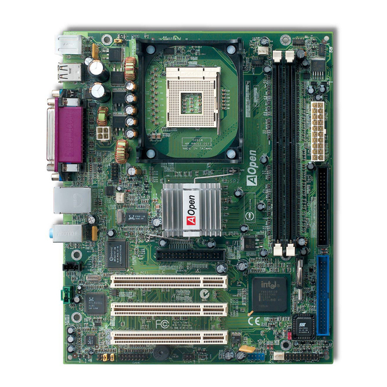
Page 15: Motherboard Map
JP14 CMOS Clear Jumper USB 2.0 Connector CPUFan1 Connector SYSFAN3 Connector 184-pin DIMMx2 Front Panel Connector supports DDR266 (Max. to 2GB) 4Mbit Flash ROM BIOS ATX Power Connector ATA 66/100 IDE Connector x2 PS. Here we use MX4LR-GN motherboard as illustration. -
Page 16: Block Diagram
PC-266 DDR SDRAM Up to 2GB 32-bit PCI Slot x3 DIMM Socket x2 Socket 478 400MHz /533MHz System Bus Intel Pentium 4 Intel PCI Bus 845GL MCH Primary 845 GV GMCH 33/66100 Channel IDE Drive x4 Secondary Channel RealTek Intel ICH4 AC97 CODEC RealTek... -
Page 17: Mx4Lr-Gn/Mx4Gvr-Gn
This chapter describes jumpers, connectors and hardware devices of this motherboard. Note: Electrostatic discharge (ESD) can damage your processor, disk drives, expansion boards, and other components. Always observe the following precautions before you install a system component. Do not remove a component from its protective packaging until you are ready to install it. Wear a wrist ground strap and attach it to a metal part of the system unit before handling a component. -
Page 18: About "Optional" And "Upgrade Optional
“Optional” for you to choose. Some optional functions that can be upgraded by users, we call them “Upgrade Optional”. As for those optional functions that can’t be upgraded by ourselves, we call them “Optional”. If needed, you can contact our local distributors or resellers for purchasing “Upgrade Optional” components, and again you can visit AOpen official web site: www.aopen.com... -
Page 19: Jp14 Clear Cmos Data
You can clear CMOS to restore system default setting. To clear the CMOS, follow the procedure below. Turn off the system and unplug the AC power. Remove ATX power cable from connector PWR2. Locate JP14 and short pins 2-3 for a few seconds. Return JP14 to its normal setting by shorting pins 1 &... - Page 20 ® This motherboard supports Intel Pentium 4 Socket 478 series CPU. Be careful of CPU orientation when you plug it into CPU socket. 2. Locate Pin 1 in the socket and look for a cut edge on the CPU upper 1.
-
Page 21: Cpu Installation
3. Press down the CPU socket lever and finish CPU installation. CPU cut edge Note: If you do not match the CPU socket Pin 1 and CPU cut edge well, it may damage the CPU. Note: This socket supports Micro-FC-PGA2 package CPU, which is the latest CPU package developed by Intel. - Page 22 This motherboard comes with a retention module attached on the CPU socket when shipped, we strongly recommend you to install AOpen special designed CPU Fan as shown below on the retention module for better heat dissipation. Please install the CPU Fan correctly as the following pictures shown.
-
Page 23: Cpu Jumper-Less Design
CPU VID signal and SMbus clock generator provide CPU voltage auto-detection and allows the user to set the CPU frequency through the BIOS setup, therefore no jumpers or switches are used. The disadvantages of the Pentium based jumper-less designs are eliminated. There will be no worry of wrong CPU voltage detection. Clock Generator ®... - Page 24 ” “ ” With this motherboard, AOpen provides a very special, useful feature for overclockers. When you power-on the system, the BIOS will check last system POST status. If it succeeded, the BIOS will enable “Watch Dog ABS” function immediately, and set the CPU frequency by user’s setting that stored in the BIOS.
- Page 25 Tip: If your system hangs or fails to boot because of Home overclocking, simply use <Home> key to restore the default setting or you can wait the AOpen “Watch Dog Timer” reset the system after five seconds and system will auto-detect hardware again.
- Page 26 Core Frequency = CPU Clock * CPU Ratio MX4LR-GN(100MHz x 4) CPU Core System PCI Clock = CPU FSB Clock / Clock Ratio FSB Clock Ratio Frequency EV6 Bus Speed = CPU external bus clock x 2 Celeron 1.7G 1700MHz...
-
Page 27: Cpu And System Fan Connector (With H/W Monitoring)
Plug in the CPU fan cable to the 3-pin CPU FAN connector. If you have chassis fan, you can also plug it on System Fan (FAN2) or FAN3 (AUX Fan) connector. +12V SENSOR SYSFAN2 Connector +12V SENSOR CPUFAN1 Connector Note: Some CPU fans do not have +12V SENSOR sensor pin, so that cannot support... -
Page 28: Jp28 Keyboard/Mouse Wake-Up Enable/Disable Jumper
This motherboard provides keyboard / mouse wake-up function. You can use JP28 to enable or disable this function, which could resume your system from suspend mode with keyboard or mouse installed. The factory default setting is set to “Disable”(1-2), and you may enable this function by setting the jumper to 2-3. JP28 KB/Mouse Wake-up Disable... -
Page 29: Dimm Sockets
This motherboard has two 184-pin DDR DIMM sockets that allow you to install PC266 memory up to 2GB. Both ECC and Non-ECC DDR SDRAM are supported, but you can’t install them both on DIMM. Otherwise, it will cause serious damage on memory sockets or SDRAM module. - Page 30 Please follow the procedure as shown below to finish memory installation. Make sure the DIMM module’s pin face down and match the socket’s size as depicted below. 40 pins 52 pins Insert the module straight down to the DIMM slot with both hands and press down firmly until the DIMM module is securely in place.
-
Page 31: Front Panel Connector
Attach the power LED, Keylock, speaker, power and reset switch connectors to the corresponding pins. If you enable “Suspend Mode” item in BIOS Setup, the ACPI & Power LED will keep flashing while the system is in suspend mode. Locate the power switch cable from your ATX housing. It is 2-pin female connector from the housing front panel. -
Page 32: Atx Power Connector
This motherboard comes with a 20-pin and 4-pin ATX power connector. Make sure you plug in the right direction. We strongly recommend you to connect the 4-pin 12V ATX connector before connecting the 20-pin ATX power connector and use standard power supply specially designed for Pentium 4 system. -
Page 33: Ac Power Auto Recovery
A traditional ATX system should remain at power off stage when AC power resumes from power failure. This design is inconvenient for a network server or workstation, without an UPS, that needs to keep power-on. This motherboard implements an AC Power Auto Recovery function to solve this problem. -
Page 34: Ide And Floppy Connector
Connect 34-pin floppy cable and 40-pin IDE cable to floppy connector FDC and IDE connector. The blue connector is IDE1 for clear identification. Be careful of the pin1 orientation. Wrong orientation may cause system damage. FDD Connector Pin 1 Secondary Slave Secondary Master (4th) (3rd) - Page 35 IDE1 is also known as the primary channel and IDE2 as the secondary channel. Each channel supports two IDE devices that make a total of four devices. In order to work together, the two devices on each channel must be set differently to Master and Slave mode.
-
Page 36: Irda Connector
The IrDA connector can be configured to support wireless infrared module, with this module and application software such as Laplink or Windows 95 Direct Cable Connection, the user can transfer files to or from laptops, notebooks, PDA devices and printers. This connector supports HPSIR (115.2Kbps, 2 meters) and ASK-IR (56Kbps). Install the infrared module onto the IrDA connector and enable the infrared function from BIOS Setup, UART Mode, make sure to have the correct orientation when you plug in the IrDA connector. -
Page 37: Color Coded Back Panel
The onboard I/O devices are PS/2 Keyboard, PS/2 Mouse, serial ports COM1 and VGA, Printer, USB, AC97 sound and game port. The view angle of drawing shown here is the back panel of the housing. SPP/EPP/ECP Parallel Port LAN Port PS/2 Mouse Connector Line-In... -
Page 38: Support 10/100 Mbps Lan Onboard
The South Bridge ICH4 includes a fast Ethernet controller on chip. On the strength of Realtek 8101L LAN controller on board, which is a highly-integrated Platform LAN Connect device, it provides 10/100M bps Ethernet for office and home use, the Ethernet RJ45 connector is located on top of USB connectors. -
Page 39: Com2 Connector
This motherboard provides two serial ports. One of them is on back panel connector, and the other is on the upper left of board. With proper cable, you can connect it to the back panel of chassis. Pin 1 SOUT RTS# DOD# DSR#... -
Page 40: Support Front Usb 2.0 Connector
This motherboard provides six 2.0 connectors to connect USB devices, such as mouse, keyboard, modem, printer, etc. There are four connectors on the back panel. You can use proper cables to connect the Front USB connector to USB modules or front panel of chassis. Pin 1 USB 2.0 Connector SBD2-... -
Page 41: Case Open Connector
The “CASE OPEN” header provides chassis intrusion-monitoring function. To make this function works, you have to enable it in the system BIOS, connect this header to a sensor somewhere on the chassis. So, whenever the sensor is triggered by lights or the opening of the chassis, the system will send out beep sound to inform you. -
Page 42: Cd Audio Connector
This connector is used to connect CD Audio cable from CDROM or DVD drive to onboard sound. CD-IN Connector... -
Page 43: Aux-In Connector
This connector is used to connect MPEG Audio cable from MPEG card to onboard sound. R GNDGND AUX-IN Connector... -
Page 44: Front Audio Connector
If the housing has been designed with an audio port on the front panel, you’ll be able to connect onboard audio to front panel through this connector. By the way, please remove 5-6 and 9-10 jumper caps from the Front Audio Connector before connecting the cable. -
Page 45: Battery-Less And Long Life Design
This Motherboard implements Flash ROM and a special circuit that allows you to save your current CPU and CMOS Setup configurations without the need of a battery. The RTC (real time clock) can also keep running as long as the power cord is plugged. -
Page 46: Cpu Over-Current Protection
CPU, memory, HDD, add-on cards installed on this motherboard may be damaged because of component failure, human operating error or unknown nature reason. AOpen cannot guaranty the protection circuit will always work perfectly. -
Page 47: Hardware Monitoring
CPU temperature. If any of these systems’ status goes wrong, there will be an alarm through the chassis external speaker or buzzer of motherboard (if existed) to warn the user. Fan Speed AOpen H/W Monitoring Detection Utility... -
Page 48: Resettable Fuse
Traditional motherboard has fuse for Keyboard and port to prevent over-current or shortage. These fuses are soldered onboard that when it is broken (function as protecting the motherboard), user still cannot replace it and the motherboard is still malfunctioning. With expensive Resettable Fuse, the motherboard can be resumed back to normal function after the fuse had done its protection job. -
Page 49: 2200Μf Low Esr Capacitor
CPU power. The idea of where to put these capacitors is another know-how that requires experience and detail calculation. Not only that, MX4LR-GN / MX4GVR-GN implements 2200μF capacitors, which is much larger than normal capacitor (1000 and 1500μf) and it provides better stability for CPU power. -
Page 50: Layout (Frequency Isolation Wall)
For high frequency operation, especially overclocking, layout is the most important factor to make sure chipset and CPU working in stable condition. The layout of this motherboard implements AOpen’s unique design called “ Frequency Isolation Wall”. Separating each critical portion of motherboard into... -
Page 51: Enlarged Aluminum Heatsink
Cool down CPU and Chipset is important for system reliability. Enlarged aluminum heat sink provides better heat consumption especially when you are trying to over clocking the CPU. -
Page 52: Wake On Modem / Wake On Lan / Wake On Pci Card
s motherboard implements special circuit to support Wake On Modem, Wake On LAN and Wake On PCI Card. Green PC suspend mode does not really turn off the system power supply, it can be triggered by Modem, LAN or Other PCI Cards and resume back to active. -
Page 53: Open Jukebox Player
Here we are pleased to provide you a brand-new powerful interface—Open JukeBox. Without any cost you can have your PC turn into a fashionable CD player! This latest Open JukeBox motherboard aims at helping you directly operate your CD player on the PC without any hassle of entering Windows operation system. - Page 54 How Your Open JukeBox Works The operation of Open JukeBox Player is the same as other CD players. By pressing specific keys on the keyboard you will find playing Open JukeBox Player couldn’t be easier than the traditional CD Players. Below is the function description of respective buttons.
- Page 55 Your Open JukeBox Settings in BIOS There are three Open JukeBox settings in BIOS as follows. Auto: The default setting is “Auto” with which the Open JukeBox will automatically check the CD player every time you power on. The Open JukeBox will automatically be launched when it detects a music CD in your CD player. Press Insert Key: Choosing this setting will allow a reminder message popped up on the screen during BIOS POST.
- Page 56 Except these powerful functions above, Open JukeBox Player is also equipped with another fancy feature for you to change its “skin”. You can download as many skins as you want from AOpen Website, and changing them whenever you want by using this useful utility – EzSkin – which may also be downloaded from our website.
-
Page 57: Vivid Bios Technology
VividBIOS to experience the lively vivid colorful POST screen! Unlike earlier graphic POST screen, which could occupy the whole screen and mask text information during POST, AOpen VividBIOS deals with graphics and texts separately, and makes them running simultaneously during POST. With this innovative design, VividBios now brings you a beautiful and sleek 256 colors screen without missing any important information shown on POST screen. -
Page 58: Driver And Utility
There are motherboard drivers and utilities included in AOpen Bonus CD disc. You don’t need to install all of them in order to boot your system. But after you finish the hardware installation, you have to install your operation system first (such as Windows 2000/XP) before you can install any drivers or utilities. -
Page 59: Installing Intel® Chipset Software Installation Utility
® ® Windows 95/98 cannot recognize this chipset, because it was released before the Intel 845GL / 845GV chipset. You can install the Intel INF Update Utility from the Bonus Pack CD disc auto-run menu to eliminate the “?” marks. -
Page 60: Intel Vga Driver
You can install Intel VGA Driver to get the best graphics function of the chipset. You can find it in the AOpen Bonus Pack CD disc. -
Page 61: Installing Intel Iaa Driver
You can install Intel IAA Driver to increase the performance of software applications and reduce PC boot times. You can find it in the AOpen Bonus Pack CD disc. -
Page 62: Installing Onboard Sound Driver
This motherboard comes with AC97 CODEC. You can find the audio driver from the Bonus Pack CD disc auto-run menu. -
Page 63: Installing Lan Driver
This motherboard integrates Realtek 10/100Mbps PCI LAN Chip. You can find LAN driver from the Bonus Pack CD disc auto-run menu. - Page 64 Installing Windows 95 (Golden version), Win95A, OSR2, Windows NT v4.0 driver for Realtek RTL8139 PCI Fast Ethernet adapter. [Windows 95 (Golden version), Win95A and OSR2] Installing driver procedure on Microsoft Windows 95: ---------------------------------------------------------------------- 1. Ask you to select which driver you want to install, select "Driver from disk provided by hardware manufacturer". 2.
- Page 65 2. In the Control Panel window, choose the "Network" icon. 3. In the Network Settings dialog box, choose the "Add Adapter" button. The Add Network Adapter dialog box appears. 4. In the list of network cards, select "<other> Requires disk from manufacturer", and then press <Enter> button. 5.
- Page 66 Enter Windows NT and follow above setup procedure step 2,in the "Network Settings" dialog box, choose the "Configure.." button. The "Input Ethernet ID" dialog box appears and input adapter's Ethernet ID. Last step to select OK and close NETWORK SETUP. Select SKIP if only one adapter is installed on this computer.
-
Page 67: Installing Usb 2.0 Driver
This motherboard has six USB 2.0 ports. You can find USB driver from the Bonus Pack CD disc auto-run menu. - Page 68 Windows 2000 Installation Guide ********************************************************** Installing Driver in Existing Windows 2000 System *********************************************************** After enabling the USB 2.0 controller and rebooting your system, Windows 2000 setup will show a "New Hardware Found" dialog box. Under Windows 2000, "Universal Serial Bus (USB) Controller" will be displayed. 1.
- Page 69 1. From Windows 2000, open the Control Panel from "My Computer" followed by the System icon. 2. Choose the "Hardware" tab, and then click the "Device Manager" tab. 3. Click the "+" in front of "Universal Serial Bus controllers". "Intel PCI to USB Enhanced Host Controller A1" should appear. Windows XP Installation Guide ********************************************************* Installing Driver in Existing Windows XP System...
- Page 70 ****************************************** Confirming Windows XP Installation ****************************************** Tools/Folder Options/View. Change below item: Enable "Display the full path in the title bat". Enable "Show Hidden files and folders". Disable "Hide extensions of known files types". Disable "Hide protected operating system files (Recommended)". Check USB driver version from My Computer, Local Disk C:, Show the content of this drive, Windows directory, Show the content of this drive, System32 directory, Show the content of this drive, Drivers directory, Show the content of this drive, View, details.
- Page 71 2. Copy all USB files from CD to HDD. 1. Copy all test drivers to %windir%\driver cache\i386. 2. Copy all test drivers to %windir%\system32\dllcache You need to copy file to this directory first. Otherwise, Windows XP will replace file from this directory to system32\drivers. 3.
-
Page 72: Acpi Suspend To Hard Drive
ACPI Suspend to Hard Drive is basically controlled by Windows operation system. It saves your current work (system status, memory and screen image) into hard disk, and then the system can be totally power off. Next time, when power is on, you can resume your original work directly from hard disk within few seconds without go through the Windows booting process and run your application again. -
Page 73: System Requirement
System Requirement AOZVHDD.EXE 1.30b or later. Delete config.sys and autoexec.bat. Fresh installation of Windows 98 on a new system 1. Execute "Setup.exe /p j" to install Windows 98 2. After Windows 98's installation is complete, go to the Control Panel > Power Management. a. - Page 74 memory size the longer this process will take Changing from APM to ACPI (Windows 98 only) 1. Run "Regedit.exe" a. Go through the following path HKEY_LOCAL_MACHINE SOFTWARE MICROSOFT WINDOWS CURRENT VERSION DETECT b. Select "ADD Binary" and name it as "ACPIOPTION". c.
- Page 75 4. Run "Add New Hardware" again and it will find "Advanced Power Management Resource". 5. Click "OK" Tip: Currently we found only ATI 3D Rage Pro AGP card would support ACPI suspend to disk. Please refer to AOpen web site for latest update...
-
Page 76: Acpi Suspend To Ram (Str)
This motherboard supports ACPI Suspend to RAM function. With this function, you can resume your original work directly from DRAM without going through the Windows 98 booting process and run your application again. Suspend to DRAM saves your current work in the system memory, it is faster than Suspend to Hard Drive but requires power supplied to DRAM, while Suspend to Hard Drive requires no power. - Page 77 To implement ACPI Suspend to DRAM, please follow the procedures as below: System Requirement An ACPI OS is required. Currently, except Windows 95 and Windows NT, all other Windows Systems support ACPI. ® The Intel Chipset Software Installation Utility must have been installed properly. Procedures Changed the following BIOS settings.
-
Page 78: Award Bios
BIOS provides critical low-level support for standard devices such as hard disk drives, serial and parallel ports. Most BIOS setting of MX4LR-GN / MX4GVR-GN had been optimized by AOpen’s R&D engineering team. But, the default setting of BIOS still can’t fine-tune the chipset controlling entire system. Hence, the rest of this chapter is intended to guide you through the process of configuring your system using setup. -
Page 79: How To Use Award™ Bios Setup Program
Award™ BIOS setup program. The following table provides details about how to use keyboard in the Award™ BIOS setup program. By the way, all products of AOpen also provides a special function in the BIOS setup, you can press <F3> key selecting preferred menu language to display. - Page 80 Description Load fail-save setting value from CMOS. Load turbo setting value from CMOS. Save changed setting and exit setup program.
-
Page 81: How To Enter Bios Setup
After you finish the setting of jumpers and connect correct cables. Power on and enter the BIOS Setup, press <Del> during POST (Power-On Self Test). Choose "Load Setup Defaults" for recommended optimal performance. Warning: Please avoid of using "Load Turbo Defaults", unless you are sure your system components (CPU, DRAM, HDD, etc.) are good enough for turbo setting. -
Page 82: Bios Upgrade Under Windows Environment
98SE/ME, NT4.0/2000, or even the latest Windows XP. In the meanwhile, in order to provide a much more user-friendly operating environment, AOpen EzWinFlash is natively designed to have multi-language function to provide easier way for users’ usage in changing BIOS setting. - Page 83 1. Download the new version of BIOS package zip file from AOpen official web site. (ex: http://www.aopen.com) 2. Unzip the download BIOS package (ex: WMX4LRGN102.ZIP) with WinZip (http://www.winzip.com) in Windows environment.
-
Page 84: Glossary
Basically, AC97 CODEC is the standard structure of PCI sound card. As we know, computer is digital-based, but music is based on analog-based. Therefore, there must be a process to turn digital into analog during the last stage processing of sound in computer. -
Page 85: Agp (Accelerated Graphic Port)
The main function of AGP simply put is to tell monitor what screen information had to be shown, a visual transmission device actually. With the rapid developing of AGP card, we can see that it had been developed from single colorful AGP card to 2D and 3D graphic. -
Page 86: Bios (Basic Input/Output System)
DMA, data transfer rate is 16.6MHz/s. Ultra DMA, data transfer rate is 16.6MHz x 2 = 33MB/s. ATA/66, data transfer rate is 16.6MHz x 4 = 66MB/s. ATA/100, data transfer rate is 16.6MHz x 6 = 100MB/s. ATA/133, data transfer rate is 16.6MHz x 8 = 133MB/s. (ATA/133 uses both rising edge and falling edge as ATA/66 but clock cycle time is reduced to 30ns.) BIOS, is a set of assembly routine/program that reside in EPROM... -
Page 87: Cnr (Communication And Networking Riser)
The CNR specification provides the PC industry the opportunity to deliver a flexible and cost reduced method of implementing LAN, home networking, DSL, USB, wireless, audio and modem subsystems widely used in today's "connected PCs". The CNR specification is an open industry specification and is supported by OEMs, IHV card manufacturers, silicon supplier and Microsoft. -
Page 88: Eprom (Erasable Programmable Rom)
Traditional motherboard stores BIOS code in EPROM. EPROM can only be erased by ultra-violet (UV) light. If BIOS has to be upgraded, you need to remove EPROM from motherboard, clear by UV light, re-program, and then insert back. EV6 Bus is the technology of Alpha processor from Digital Equipment Corporation. EV6 bus uses both rising and falling clock edge to transfer data, similar as DDR RAM or ATA/66 IDE bus. -
Page 89: Flash Rom
Flash ROM can be re-programmed by electronic signals. It is easier for BIOS to upgrade by a flash utility, but it is also easier to be infected by virus. Because of increase of new functions, BIOS size is increased from 64KB to 512KB (4M bit). Hyper-Threading technology is an innovative design from Intel that enables multi-threaded software applications to process threads in parallel within each processor resulting in increased utilization of processor execution resources. -
Page 90: Parity Bit
IEEE1394 is very easy to connect (Like USB1.1/2/0). The parity mode uses 1 parity bit for each byte, normally it is even parity mode, that is, each time the memory data is updated, parity bit will be adjusted to have even count "1" for each byte. When next time, if memory is read with odd number of "1", the parity error is occurred and this is called single bit error detection. -
Page 91: Post (Power-On Self Test)
The BIOS self-test procedure after power-on, sometimes, it is the first or the second screen shown on your monitor during system boot. PSB Clock means the external bus clock of CPU. CPU internal clock = CPU PSB Clock x CPU Clock Ratio A DRAM technology developed by Rambus Corporation*, to achieve high speed of memory through the use of multiple channels in parallel by 16-bits. -
Page 92: Sdram (Synchronous Dram)
SDRAM is one of the DRAM technologies that allow DRAM to use the same clock as the CPU host bus (EDO and FPM are asynchronous and do not have clock signal). It is similar as PBSRAM to use burst mode transfer. SDRAM comes in 64-bit 168-pin DIMM and operates at 3.3V, and have been gradually replaced by DDR RAM. -
Page 93: Usb 2.0 (Universal Serial Bus)
A Universal Serial Bus (USB) is an external bus (an interconnect) standard that supports data transfer rates of 12 Mbps. A single USB port can be used to connect up to 127 peripheral devices, such as mouse, modems and keyboards. Introduced in 1996, USB has completed replaced serial and parallel ports. -
Page 94: Zip File
A compressed file format to reduce file size. To unzip file, run shareware PKUNZIP (http://www.pkware.com/) for DOS and other operating system or WINZIP (http://www.winzip.com/) for windows environment. -
Page 95: Troubleshooting
If you encounter any trouble to boot you system, follow the procedures accordingly to resolve the problem. Start Turn off the power and unplug the AC power cable, then remove all of the add-on cards and cables, including VGA, IDE, FDD, COM1, COM2 and printer. - Page 96 Continue Install the VGA card. Then connect your monitor and keyboard. Turn on the power and check if the power supply and CPU fan work properly. The problem is probably caused by power supply or motherboard failure. Next Please contact your reseller or local distributor for repairing.
- Page 97 Continue Perhaps your VGA card Check if there is display? or monitor is defective. Press <Ctrl> and <Alt> key at the same time, hold them and then press <Del> to reboot the system. It is very possible that your Check if the system keyboard is defective.
- Page 98 Continue During system rebooting, press <Del> to enter BIOS setup. Choose “Load Setup Default”. Turn off the system and re-connect IDE cable. The problem should be Check if the system can caused reboot successfully? cable or HDD itself. Re-install the operating system such as Windows 98.
-
Page 99: Technical Support
Dear Customer, Thanks for choosing AOpen products. To provide the best and fastest service to our customer is our first priority. However, we receive numerous emails and phone-calls worldwide everyday, it is very hard for us to serve everyone on time. We recommend you follow the procedures below and seek help before contact us. - Page 100 AOpen eForum is provided to discuss our products with other users, in which your problem probably had been discussed before or will be answered. After log on, you may select your preferred language under “Multi-language”. http://club.aopen.com.tw/forum/ Contact Distributors/Resellers: We sell our products through resellers and integrators. They should know your system configuration very well and should be able to solve your problem efficiently and provide important reference for you.
- Page 101 Model name and BIOS version can be found on upper left corner of first boot screen (POST screen). For example: MX4LR-GN R1.00 Feb. 1. 2003 AOpen Inc. Phoenix-Award Plug and Play BIOS Extension v1.0A Copyright © 2003, Award Software, Inc. MX4LR-GN is model name of motherboard, R1.00 is BIOS version.
- Page 102 Be able to join the discussions of web-based news groups. AOpen makes sure that the information you provide is encrypted, so that it cannot be read or intercepted by other people or companies. Further, AOpen will not disclose any of information you submitted under any conditions. Please consult our...
- Page 103 Please do not hesitate contact us if you have any problem about our products. Any opinion will be appreciated. Pacific Rim Europe America AOpen Inc. AOpen Computer b.v. AOpen America Inc. Tel: 886-2-3789-5888 Tel: 31-73-645-9516 Tel: 1-510-489-8928 Fax: 886-2-3789-5899 Fax: 31-73-645-9604...
Need help?
Do you have a question about the MX4LR-GN and is the answer not in the manual?
Questions and answers