
Related Manuals for Allied Telesis CentreCOM AT-200 Series


Summary of Contents for Allied Telesis CentreCOM AT-200 Series
- Page 1 CentreCOM™ AT-200 Series Single Port Transceiver User Manual PN 613-10423-00 Rev A 951117...
- Page 2 RADIATED ENERGY U.S. Federal Communications Note: This equipment has been tested and found to comply with the limits for a Class A digital device pursuant to Part 15 of FCC Rules. These limits are designed to provide reasonable Electrical Safety and Installation protection against harmful interference when the equipment is operated in a commercial environment.
- Page 3 Die Sicherheitsprüfung erfolgte nur für die Modelle der Serie AT-200 als “nicht für Patienten zugelassene Geräte” durch Underwriters Laboratories Inc. gemäß UL544, der Norm für medizinische und zahntechnische Geräte. GEFAHR DURCH BLITZSCHLAG GEFAHR: Keine Arbeiten am Gerät oder an den Kabeln während eines Gewitters ausführen INSTALLATION Betjeningstemperatur: Dieses Produkt wurde für den Betrieb in einer Umgebungstemperatur von nicht mehr als 50 C entworfen.
- Page 4 ENERGIE RAYONNEE Ce matériel a été testé et est certifié conforme par la réglementation américaine aux normes définies pour les appareils de classe A. Ce matériel a été testé et est certifié conforme par la réglementation allemande Vfg 243/1991 aux normes définies pour les appareils de classe B. SECURITE La sécurité...
- Page 5 PERICOLO DI FULMINI PERICOLO: NON LAVORARE sul dispositivo o sui CAVI durante PRECIPITAZIONI TEMPORALESCHE. INSTALLAZIONE Temperatura di funzionamento: Questo prodotto è concepito per una temperatura ambientale massima di 50 gradi centigradi. Tutti i paesi: installare il prodotto in conformità alle vigenti normative elettriche nazionali. UTSTRÅLT ENERGI Dette kommersielle produktet har blitt testet og er i samsvar med amerikanske krav for et A- Klasse apparat.
- Page 6 ENERGIA RADIADA Este producto comercial ha sido probado y cumple con las normas requeridas en los EE. UU. para un dispositivo de Clase A. Este producto ha sido probado y cumple con los requisitos Vfg 243/1991 de Alemania para un dispositivo de Clase B.
-
Page 7: Table Of Contents
Table of Contents Overview ..................... 1 Installation ..................1 Heartbeat configuration ..............1 Thick Ethernet installation with coaxial active tap assembly (for model AT-206) ..........2 Data cabling considerations ..........3 Tapping the cable and assembling the transceiver ....3 Thick Ethernet installation with coaxial N-series tap (for model AT-208) .............. -
Page 8: Overview
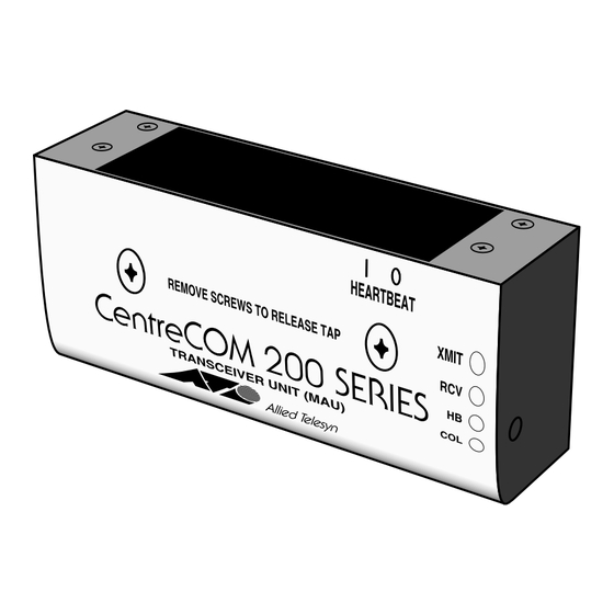
Overview CentreCOM™ AT-200 Series Single Port Transceivers are highly reliable compact Media Access Units (MAUs) for users of Ethernet Local Area Networks (LANs). They provide the electronic and physical interface between the IEEE 802.3 coaxial cable and a Data Terminal Equipment (DTE) station. The AT-200 transceiver is available in a variety of configurations, all of which meet the transceiver compliance requirements of IEEE 802.3 and are compatible with Ethernet Version 1.0 and 2.0. -
Page 9: Thick Ethernet Installation With Coaxial Active Tap Assembly (For Model At-206)
When necessary, you can enable the SQE test using the Heartbeat switch located on the Printed Circuit Board (PCB) inside the transceiver body. This must be done without the tap body installed in the transceiver. Checking and setting the SQE/Heartbeat switch If the tap body is not installed in the transceiver (for models AT-205 and AT-206), skip to step 3. -
Page 10: Data Cabling Considerations
AT-200 Single Port Transceiver Data cabling considerations. When configuring 10BASE5 coax segments, IEEE 802.3 specifications provide the following rules to follow: MAU attachments limited to 100 per segment MAU attachments spaced at multiples of 2.5 meters (8.2 ft.) measured accurately from the cable end (50 terminator included) Segment length cannot exceed 500 meters (1,640 ft.) Worst case “end-to-end”... -
Page 11: Figure 2: Assembling The Coaxial Active Tap
Place the cable in the cable channel of the tap body. Socket screw Clamp assembly Pressure block Cable Braid terminator (2) Tap body Probe assembly Figure 2: Assembling the Coaxial Active Tap Slide the clamp assembly onto the tap body until it stops. Using the hex wrench, thread the button socket screw into the clamp frame until the pressure block bottoms on the clamp track and holds the cable securely. -
Page 12: Thick Ethernet Installation With Coaxial N-Series Tap (For Model At-208)
AT-200 Single Port Transceiver 11. To install the transceiver, align the opening on the transceiver body so that the diagnostic LEDs are facing you. (The transceiver is reversible front to back.) Gently guide the tap body into the transceiver opening so that the probe post and the two braid terminator posts are aligned with the three gold-colored circuit board contacts. -
Page 13: Data Cabling Considerations
The SQE/Heartbeat is factory set to the “0” (disabled) position. Unless your application calls for the heartbeat signal to be enabled, leave this switch in the “0” position. (See “Heartbeat configuration” on page 1.) Figure 4: AT-200 with N-Series Thicknet Backbone Connector (AT-208) Data cabling considerations. -
Page 14: Thin Ethernet Installation With Bnc Tap (For Models At-204 And At-207)
AT-200 Single Port Transceiver Thin Ethernet installation with BNC tap (for models AT-204 and AT-207) Before installing the AT-204 or AT-207 Single Port Transceiver, check to see that the transceiver package contents are complete. If any of the following items are missing or damaged, contact your sales representative. -
Page 15: Data Cabling Considerations
The SQE/Heartbeat is factory set to the “0” (disabled) position. Unless your application calls for the heartbeat signal to be enabled, leave this switch in the “0” position. (See “Heartbeat configuration” on page 1.) Data cabling considerations. When configuring 10BASE2 coax segments, IEEE 802.3 specifications provide the following rules to follow: MAU attachments limited to 29 per cable segment MAU attachments spaced at no less than 0.5 meter (1.64 ft.) -
Page 16: Checking Operation
AT-200 Single Port Transceiver AUI cables may have a maximum 257 ns propagation delay, as used for computing the worst case propagation delay of a cable system AUI cable propagation delay is approximately 5.13 ns/meter AUI cable internally consists of four shielded twisted pair wires with an overall shield and drain wire;... -
Page 17: Incident Summary
Technical Support Fax Order Form Name ___________________________________________________________ Company ________________________________________________________ Address _________________________________________________________ City ____________________ State/Province ____________________________ Zip/Postal Code _______________ Country ____________________________ Phone ___________________________ Fax ____________________________ Incident Summary Model number of Allied Telesyn product I am using _______________________ Network software products I am using (e.g., network managers) _ _____________ _______________________________________________________________ Brief summary of problem___________________________________________ _______________________________________________________________... - Page 18 AT-200 Single Port Transceiver CentreCOM AT-200 Manual Feedback Form Please tell us what additional information you would like to see discussed in the manual. If there are topics you would like information on that were not covered in the manual, please photocopy this page, answer the questions and fax or mail this form back to Allied Telesyn.
- Page 19 The information provided herein is subject to change without notice. In no event shall Allied Telesyn International Corp. be liable for any incidental, special, indirect, or consequential damages whatsoever, including but not limited to lost profits, arising out of or related to this manual or the information...
Need help?
Do you have a question about the CentreCOM AT-200 Series and is the answer not in the manual?
Questions and answers