
Subscribe to Our Youtube Channel
Related Manuals for Zibro Laser 56


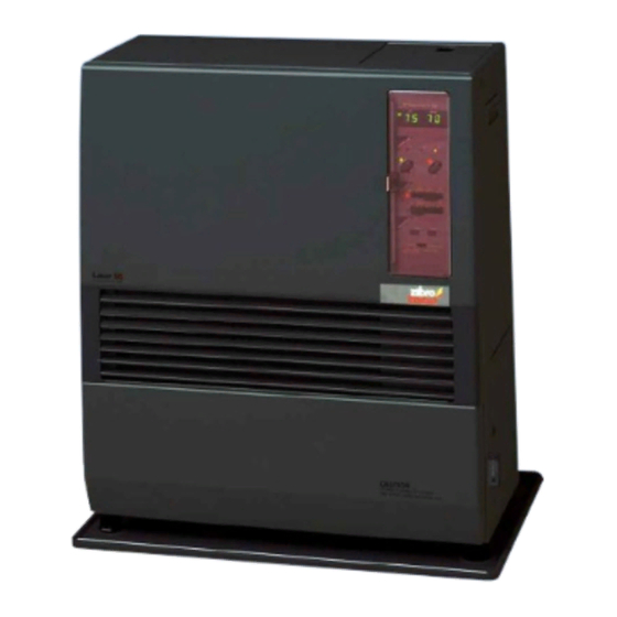
Summary of Contents for Zibro Laser 56
- Page 1 Laser 56 MANUEL D’UTILISATION GEBRAUCHSANWEISUNG BRUGSANVISNING OPERATING INSTRUCTIONS ISTRUZIONI D’USO > GEBRUIKSAANWIJZING...
-
Page 2: Operating Instructions
OPERATING INSTRUCTIONS Dear Sir, Madam, Congratulations with your purchase of the Zibro, the number one brand among movable heaters. You have purchased a first-class quality product, which will serve you for many years to come. This, of course, provided you use the heater correctly. -
Page 3: What You Need To Know In Advance
WHAT YOU NEED TO KNOW IN ADVANCE THE RIGHT FUEL Only use Class C1 paraffin fuel in accordance with BS2869: Part 2, or equivalent. Your Zibro heater has been designed for use with high-quality water-free pure paraffin oil, such as Zibro Extra or Zibro Kristal. Only fuels of this kind will ensure clean and proper burning. -
Page 4: Chapter 1, Installation
Chapter 1, INSTALLATION 1. Introduction Recommended tool kit This chapter contains all the relevant information, 1. Crosshead screwdriver specifically: 2. Steel tape measure 3. Felt-tip pen or pencil • Installation specifications 4. Cement for exterior use • List of installation tools 5. - Page 5 G) Check that all parts are present. Only the standard feed and exhaust system is supplied with the heater. More than 60 cm More than 10 cm More than 30 cm More than 30 cm More than 1,5 m Laser 56 Fig. 1-1: Gaps heater/exhaust pipe...
- Page 6 Chapter 1, INSTALLATION Flammable object Flammable object Not less than 60 cm Not less than 45 cm Not less Non-flamma- than 45 cm ble object Not less than 60 cm 45°C Not less than 30 cm Exhaust pipe Not less than 20 cm Fig.
- Page 7 (305 mm) Fuel inlet (82 mm) Floor (31 mm) (127 mm) Laser 56 Fig. 1-3 Template Do not remove any components from the heater. Always contact your dealer if repairs are required. If the electricity cable is damaged, this may only be replaced with type H05 VV-F and by a recognised installer.
- Page 8 Standard installation parts The following list of standard installation parts is sup- plied with your heater. It may be necessary to order extra parts from your Zibro dealer if other installation methods are required. Base plate (1) Wall hooks (2 set)
- Page 9 Chapter 1, INSTALLATION Right-angled exhaust pipe bend (1) Discharge chute (1) Right-angled air hose (2) Flexible air hose (1) Hose clip (2)
- Page 10 Chapter 1, INSTALLATION 1. For the standard installation, use the template sup- ly. Use cellotape or small nails to attach the template to plied to position the hole for the exhaust pipe correct- the desired position on the wall (see Fig. 4). Tape Fig.
- Page 11 Chapter 1, INSTALLATION 3. Install the inner flue pipe. a. For wall thickness 230~320mm. From inside the room, insert the inner flue pipe through the hole. Make sure the arrow on the inner flue pipe is pointing up. Secure the inner flue pipe to the wall with the three wood screws. (See Fig. 7) inside Outsida 230~320mm...
- Page 12 Chapter 1, INSTALLATION c. From outside, insert the outer flue pipe through the hole. Secure the outer flue pipe to the wall by turning it clockwise. This locks the two halves together (See Fig. 9). IMPORTANT: Make sure the arrow on the outer flue pipe frange is pointing up. Make sure to secure the outer flue pipe well.
- Page 13 Chapter 1, INSTALLATION 5. In case the circuit board cover gets in the way of the connection of the standard flue pipe, use the exten- sion pipe (S) for the exhaust outlet mouth of the heater (See Fig. 11). Exhaust Extension pipe (S) Fig.
- Page 14 Chapter 1, INSTALLATION 7. Fasten the right-angled air hose to the inlet with the bend). Attach the right-angled exhaust bend to the hose clip. Attach the right-angled exhaust bend to the outlet by sliding the pipe lock into the outlet clip (See exhaust pipe with the pipe holder (attach the pipe Fig.
- Page 15 Available fuel supply options • Check whether the heater has been connected to a The fuel supply of the Laser 56 can be set up as follows: suitable socket. • Check that a suitable quantity of petroleum is in the Removable fuel tank fuel tank.
- Page 16 Important: Ensure that the fuel pipe is free of dust and waste particles. These particles may cause problems in the fuel receptacle. Fuel tank placed outside Laser 56 Fuel drainage container with unlocking button Fuel filter: Preferred type – water intake cut-off valve 2.5 m (max.)
-
Page 17: Chapter 2, Operation
This chapter provides all the information required for the operation of the Laser heater system. All specified operating procedures must be carried out in the order in which they are described. 2. Laser 56 heater specifications Medium High Heat yield (W) - Page 18 Chapter 2, OPERATION 3. Operating elements and lights 6. IInformation display 7. Operating mode lights 7. Operating mode lights 7. Operating mode lights 2. Button to activate/deactivate pro- 1. ON/OFF button grammed timer (auto-switch) 7. Operating mode lights 3. Temperature adjustment button 7.
- Page 19 Chapter 2, OPERATION 4. Prior to use switch to “OFF” to change to “MANUAL” operation. Step 1: Open the valve(s) Screw the valve on the top of the removable tank open Step 2: Switch the heater ON or open the valve for the external fuel tank and the Press the ON/OFF button until “ON”...
- Page 20 Chapter 2, OPERATION the setting by approximately 2°C, the heater is Step 1: Set the start time of the “SET-BACK” mode switched off automatically. If the room temperature drops, the heater will automatically restart in order to A. Slide the time selector switch to the “START SET- maintain the desired temperature.
- Page 21 Chapter 2, OPERATION 11. Power cuts – recovery system Manual cleaning system If a power cut occurs while the heater is in operation, The heater must be switched off during manual clea- all electrical systems will be switched off automatically. ning.
- Page 22 Chapter 2, OPERATION 14. Before consulting an expert Step 5: Remove the front panel. Step 6: Clean the inside of the heater. The following situations do not indicate defects. Before starting to clean the heater, ensure While switching the heater on or off that the interior is cool enough to touch.
-
Page 23: Chapter 3, Error Messages
Chapter 3, ERROR MESSAGES Error code Problem Cause Solution Power light is not lit. The plug is not in the socket. Insert the plug into the socket. The print plate does not function Check the fuse or contact your correctly. dealer. -
Page 24: Chapter 4, Warranty Provisions
Chapter 4, WARRANTY PROVISIONS Your heater comes with a 24-months warranty starting The warranty shall not apply to damages caused on the date of purchase. Within this period all defects by actions not in compliance with the Directions in material or workmanship will be repaired without for Use, neglect, and the use of an incorrect type any charge. - Page 25 Holloway Bank, Wednesbury tel: +43 7434 44867 West Midlands WS10 OAW fax: +43 7434 44868 tel.: +44 121 506 1818 email: pvgaustria@zibro.com fax: +44 121 505 1744 email: gases@lister.co.uk e BELGIË PVG Belgium NV/SA > ITALIA Industrielaan 55 PVG Italy SRL 2900 SCHOTEN Via Niccolò...
Need help?
Do you have a question about the Laser 56 and is the answer not in the manual?
Questions and answers