Table of Contents
Advertisement
OPERATING INSTRUCTIONS FOR
Model 3350
Oxygen Alarm Monitor
DANGER
HIGHLY TOXIC AND OR FLAMMABLE LIQUIDS OR GASES MAY BE PRESENT IN THIS
MONITORING SYSTEM.
PERSONAL PROTECTIVE EQUIPMENT MAY BE REQUIRED WHEN SERVICING THIS SYSTEM.
HAZARDOUS VOLTAGES EXIST ON CERTAIN COMPONENTS INTERNALLY WHICH MAY
PERSIST FOR A TIME EVEN AFTER THE POWER IS TURNED OFF AND DISCONNECTED.
P/N M70682
ONLY AUTHORIZED PERSONNEL SHOULD CONDUCT MAINTENANCE AND/OR SERVICING.
9/29/09
BEFORE CONDUCTING ANY MAINTENANCE OR SERVICING CONSULT WITH AUTHORIZED
REV 1
SUPERVISOR/MANAGER.
Teledyne Analytical Instruments
i
Advertisement
Table of Contents

Related Manuals for Teledyne 3350


Summary of Contents for Teledyne 3350
- Page 1 OPERATING INSTRUCTIONS FOR Model 3350 Oxygen Alarm Monitor DANGER HIGHLY TOXIC AND OR FLAMMABLE LIQUIDS OR GASES MAY BE PRESENT IN THIS MONITORING SYSTEM. PERSONAL PROTECTIVE EQUIPMENT MAY BE REQUIRED WHEN SERVICING THIS SYSTEM. HAZARDOUS VOLTAGES EXIST ON CERTAIN COMPONENTS INTERNALLY WHICH MAY PERSIST FOR A TIME EVEN AFTER THE POWER IS TURNED OFF AND DISCONNECTED.
- Page 2 Any safeguards required such as locks, labels, or redun- dancy, must be provided by the user or specifically requested of Teledyne at the time the order is placed.
- Page 3 Model 3350 complies with all of the requirements of the Com- monwealth of Europe (CE) for Radio Frequency Interference, Elec- tromagnetic Interference (RFI/EMI), and Low Voltage Directive (LVD). The following International Symbols are used throughout the Instruc- tion Manual for your visual and immediate warnings and when you...
-
Page 4: Table Of Contents
3.5.2.1 Connecting the Rechargeable Battery ..3-5 3.5.3 Analog Outputs ............3-6 3.5.4 RS-232 Port (optional) ........... 3-6 3.5.5 Alarm Relays ............3-7 3.6 Calibration ..............3-8 3.7 Operation ............... 3-9 3.8 Cell Warranty ..............3-10 3.9 Safety Checklist ............. 3-10 Teledyne Analytical Instruments... - Page 5 5.2.3 Removing the Micro-Fuel Cell ....... 5-3 5.2.4 Installing a Micro-Fuel Cell ........5-4 5.2.5 Cell Warranty Conditions ........5-4 Appendix A.1 Specifications ..............A-1 A.2 Spare Parts List ............. A-2 A.3 Reference Drawing ............A-3 A.4 Miscellaneous ..............A-3 Teledyne Analytical Instruments...
- Page 6 Since the use of this instrument is beyond the control of Teledyne, no responsibility by Teledyne, its affiliates, and agents for damage or injury from misuse or neglect of this equipment is implied or assumed.
-
Page 7: Introduction 1
Model 3350 is a microprocessor-based Oxygen Alarm Monitor for real-time measurement of the oxygen content of the atmosphere surrounding its sensor. The Model 3350 standard instrument is configured to run from an AC power source and is also available with continuous charging, DC battery backup option. -
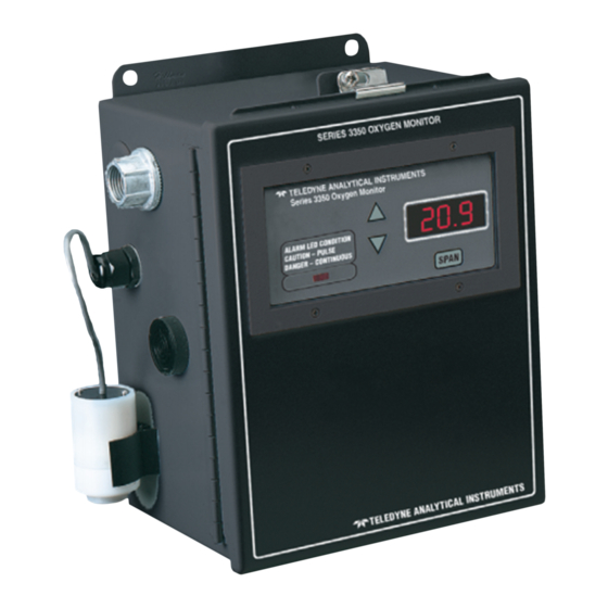
Page 8: Front Panel Description
1 Introduction Model 3350 • Two factory preset alarms, form C relay contacts, configured as Failsafe or Non-Failsafe. • Sensor failure alarm, form C relay contact, configured as Failsafe or Non-Failsafe. • Three analog outputs: two for measurement (0–10 VDC, and negative ground 4–20 mADC) and one for range identification... -
Page 9: Rear Panel Description
1-2 for the AC and DC battery backup versions of the instrument. The connectors are described briefly here and in detail in the Installation chapter of this manual. Figure 1-2 Rear Panel, Control Unit - AC (viewed from inside front door) Teledyne Analytical Instruments... -
Page 10: Introduction
1 Introduction Model 3350 Figure 1-2 Rear Panel, Control Unit - DC (viewed from inside front door) • Power Connection AC version: Universal 100–240 VAC, at 50/60Hz. The connector housing includes the fuse holder and the power switch. DC Battery Backup Version: , 10 to 36 VDC. -
Page 11: Micro-Fuel Cell Sensor
Micro-Fuel Cell Sensor 2.2.1 Principles of Operation The oxygen sensor used in the Model 3350 is a Micro-fuel Cell designed and manufactured by TAI. It is a sealed, disposable electrochemical transducer. The active components of the Micro-Fuel Cell are a cathode, an anode, and the aqueous KOH electrolyte in which they are immersed. -
Page 12: Anatomy Of A Micro-Fuel Cell
2 Operational Theory Model 3350 2.2.2 Anatomy of a Micro-Fuel Cell The Micro-Fuel Cell is made of extremely inert plastic (which can be placed confidently in practically any environment or sample stream). It is effec- tively sealed, though one end is permeable to oxygen in the sample gas. At the permeable end a screen retains a diffusion membrane through which the oxygen passes into the cell. -
Page 13: Electrochemical Reactions
Fortunately, Dalton's Law confirms that every gas in a mixture contributes the same pressure to the mixture that it would exert if it were alone in the same Teledyne Analytical Instruments... -
Page 14: Calibration Characteristics
2 Operational Theory Model 3350 amount in that same volume. This means that as long as the total pressure of the sample remains constant, the mixture can change, but the diffusion of the oxygen will be affected only by the concentration of the oxygen. -
Page 15: Electronics
NETW ORK ON AMPLIFIER SENSOR PCB Microamp Concentration Output 0–10 V dc Sensor D A C RANGE ID MICRO- CONTROL- AUDIBLE ALARM KEYBOARD DISPLA Y RELA YS ALARMS Figure 2-3: Block Diagram of the Signal Processing Electronics Teledyne Analytical Instruments... -
Page 16: Alarms
2 Operational Theory Model 3350 In the presence of oxygen the cell generates a current. The sensor has an internal thermistor compensation network. The output of the sensor is converted to millivolts. This output is fed to a volatge amplifier. The internal thermistor network provides temperature com- pensation of the sensor output. -
Page 17: Installation 3
CAUTION: Do not disturb the integrity of the cell package until the cell is to actually be used. If the cell package is punctured and air is permitted to enter, cell-life will be compromised. Teledyne Analytical Instruments... -
Page 18: Installation
3 Installation Model 3350 Installation The 3350 is designed to be wall-mounted, in a general purpose, area. The unit should be installed at viewing level in a sheltered area, if possible. The installation consists of installing the MFC, connecting the rechargeable battery (if applicable) and connecting the instrument to AC power.. -
Page 19: Power And Signal Connections
3.5 Power and Signal Connections AC and Battery Backed Standby Power This 3350 is designed to operate from 100-240VAC @ 50/60 Hz power. Connect the included power cord to the AC power as shown in Fig. 3-3 for standard AC unit and Fig. 3-4 for battery backed standby power. -
Page 20: Battery Backed Standby Power
3.5.2 Battery Backed Standby Power An optional Battery Backed Standby Power Configuration is offered on the Model 3350 for potential power failure or "brown out" conditions. Power outages will not interfere with a properly-working Model 3350 oxygen alarm if it is installed and used correctly. The standby power source uses a rechargeable lead acid battery. -
Page 21: Connecting The Rechargeable Battery
AC power (that is, under battery power). The optional battery backup version of the Model 3350 is designed to operate on standby battery power for at least 17 hours in Fail Safe mode and 48 hours in Non-Fail Safe mode (if conditions are favorable, i.e., conditions... -
Page 22: Analog Outputs
3 Installation Model 3350 3.5.3 Analog Outputs There are four DC output signal connectors with screw terminals on the panel. Recommended wire: 22 AWG minimum with 300VAC insulation. There are two wires per output with the polarity noted. The outputs are: 0–10 V % Range:... -
Page 23: Alarm Relays
Each status output is followed by a carriage return and line feed. The RS-232 protocol allows some flexibility in its implementation. Table 3-2 lists certain RS-232 values that are required by the 3350 imple- mentation. Table 3-2: Required RS-232 Options... -
Page 24: Calibration
3 Installation Model 3350 The specific descriptions for each type of alarm are as follows: Alarm #1 (CAUTION) Factory preset for OSHA Standards at 20% Oxygen. Alarm #2 (DANGER) Factory preset for OSHA Standards at 19.5% Oxygen. Sensor Fail Actuates when the output of the Micro-Fuel Cell sensor falls below the acceptable level (0.05% Oxygen). -
Page 25: Operation
Micro-Fuel Cell (MFC) installed. With the class B-3 MFC installed, the response time is less than 15 seconds at 25°C. The table below indicates the response time for some MFCs typically used in the Model 3350. Teledyne Analytical Instruments... -
Page 26: Cell Warranty
13 12 Intermediate response/long life 3.8 Cell Warranty The Class B-3 cell used in the Model 3350 is warranted for 12 months of service. Under normal operating conditions the Class B-3 cell should last 12 months in air. For special applications, optional cells are available. -
Page 27: Accessory Flow-Through Adapter
3.10 Accessory Flow-Through Adapter A flow-through adapter is available for the Series 3350 Oxygen Analyzer for those applications that require piped-in gases. The adapter consists of a sealed chamber where the instrument's probe is inserted, with two radially-oriented hose connectors to which supply and vent lines for the calibration gas are connected. - Page 28 3 Installation Model 3350 Left intentially blank 3-12 Teledyne Analytical Instruments...
-
Page 29: Operation 4
PERCENT OXYGEN meter while one of the Function buttons is being held down. Δ : Increments the displayed value upwards. • ∇ : Increments the displayed value downwards. • The Span function can be selected at any time by holding down the appropriate button. Teledyne Analytical Instruments... -
Page 30: Alarm Conditions
4 Operation Model 3350 Alarm Conditions The alarm setpoints are preset at the factory and can not be changed by the user. Alarm 1 (CAUTION) Factory preset at 20% Oxygen. Contact factory for custom Alarm Setpoints. When CAUTION Alarm (Alarm 1) is activated, the LED on the front panel will begin to blink. -
Page 31: Supplementary Information
UP button and then the DOWN button. (Pressing the UP and DOWN buttons causes the analyzer to time-out in five seconds instead of five minutes). Teledyne Analytical Instruments... - Page 32 4 Operation Model 3350 Teledyne Analytical Instruments...
-
Page 33: Maintenance 5
Alarm Oxygen Monitor Maintenance 5 Maintenance Aside from normal cleaning, the Model 3350 should not require any maintenance beyond replacement of expended Micro-Fuel Cells, and perhaps a blown fuse. Routine maintenance includes occasional recalibration, as described in chapter 4, Operation. -
Page 34: Ac With Battery Backup Version
5 Maintenance Model 3350 3. Insert a small flat-blade screwdriver into the slot in the receptacle at the end of the power module and gently pry open the fuse receptacle. The fuse holder will slide out. There are two fuses in use and are visible in the clip. -
Page 35: Ordering And Handling Of Spare Sensors
If the cell package is punctured and air is permit- ted to enter, cell-life will be compromised. WARNING: The sensor used in the Model 3350 uses electrolytes which contain substances that are extremely harmful if touched, swallowed, or inhaled. Avoid contact with ANY fluid or powder in or around the unit. -
Page 36: Installing A Micro-Fuel Cell
4. Replace the probe cap. 5.2.5 Cell Warranty Conditions The Class B-3 Micro-Fuel cell is used in the Model 3350. This cell is a long life cell and is warranted for 12 Months (under specified operating condi- tions—see Appendix) from the date of shipment. Note any Addenda attached to the front of this manual for special information applying to your instrument. -
Page 37: Appendix A.1 Specifications
4.3mA Max. Range ID: 0-10VDC (0-10mA MAX) (80mA short circuit) Enclosure: Wall Mounting, NEMA-4 enclosure. Approx. 8"(W) x 10"(H) x 6"(D) Alarms: Factory Set: CAUTION = 20.0% DANGER = 19.5% CELL FAIL Audible Buzzer Visual Red, Indicator Lamps Teledyne Analytical Instruments... -
Page 38: Spare Parts List
Appendix Model 3350 A.2 Spare Parts List Standard AC Version QTY. P/N DESCRIPTION C-65220G PC Board, Main C-70740A PC Board, Power Supply AC Version C-70875 Probe Assembly C-800 Probe Clip F-1130 Fuse (AC), 1/2A, 250 VAC IEC Type T A-20... -
Page 39: Reference Drawing
D-70680 Interconnection Diagram A.4 Miscellaneous The symbol: ~ is used on the rear of the control panel of the model 3350 to signify volts alternating current (V ac). NOTE: The MSDS on this material is available upon request through the Teledyne Environmental, Health and Safety Coordinator. - Page 40 Appendix Model 3350 Teledyne Analytical Instruments...
- Page 41 Product Name: Micro-Fuel Cells Mini-Micro-Fuel Cells, all classes Super Cells, all classes except T–5F Electrochemical Oxygen Sensors, all classes. Manufacturer: Teledyne Electronic Technologies/Analytical Instruments Address: 16830 Chestnut Street, City of Industry, CA 91749 Phone: (626) 961-9221 Technical Support: (626) 934-1673...
- Page 42 Appendix Model 3350 Section III – Physical Hazards Potential for fire and explosion: The electrolyte in the Micro-Fuel Cells is not flammable. There are no fire or explosion hazards associated with Micro-Fuel Cells. Potential for reactivity: The sensors are stable under normal conditions of use.
- Page 43 The information is believed to be correct but does not purport to be all inclusive and shall be used only as a guide. Teledyne Analytical Instruments shall not be held liable for any damage resulting from handling or from contact with the above product.
Need help?
Do you have a question about the 3350 and is the answer not in the manual?
Questions and answers