Table of Contents
Advertisement
Quick Links
Turbine Generator Gas Analyzer
OPERATING INSTRUCTIONS FOR
MODEL 2750
Turbine Generator Gas Analyzer
P/N M76700
4/09/2012
DANGER
Toxic gases and or flammable liquids may be present in this monitoring system.
Personal protective equipment may be required when servicing this instrument.
Hazardous voltages exist on certain components internally which may persist
for a time even after the power is turned off and disconnected.
Only authorized personnel should conduct maintenance and/or servicing.
Before conducting any maintenance or servicing, consult with authorized
supervisor/manager.
Teledyne Analytical Instruments
i
Advertisement
Table of Contents

Related Manuals for Teledyne 2750


Summary of Contents for Teledyne 2750
- Page 1 Turbine Generator Gas Analyzer OPERATING INSTRUCTIONS FOR MODEL 2750 Turbine Generator Gas Analyzer P/N M76700 4/09/2012 DANGER Toxic gases and or flammable liquids may be present in this monitoring system. Personal protective equipment may be required when servicing this instrument.
- Page 2 Any safeguards required such as locks, labels, or redundancy, must be provided by the user or specifically requested of Teledyne at the time the order is placed.
- Page 3 Commonly available options are listed below, with check boxes. Any that are incorporated in the instrument for which this manual is supplied are indicated by a check mark in the box. Instrument Serial Number: _______________________ Options Included in the Instrument with the Above Serial Number: Teledyne Analytical Instruments...
-
Page 4: Safety Messages
Model 2750 Safety Messages Your safety and the safety of others is very important. We have provided many important safety messages in this manual. Please read these messages carefully. A safety message alerts you to potential hazards that could hurt you or others. - Page 5 Manuals do get lost. Additional manuals can be obtained from Teledyne at the address given in the Appendix. Some of our manuals are available in electronic form via the Internet. Please visit our website at: www.teledyne-ai.com.
-
Page 6: Table Of Contents
Model 2750 Table of Contents Safety Messages ................iv Table of Contents ................. vi List of Figures ................viii List of Tables ................ix Introduction ................. 11 1.1 Overview 1.2 Analysis Ranges 1.3 Enclosure ... - Page 7 Turbine Generator Gas Analyzer Maintenance ................. 35 5.1 Routine Maintenance 5.1.1 Instrument Cleaning 5.1.2 Periodic Calibration 5.1.3 Leak Checking 5.2 Troubleshooting Appendix ..................39 A.1 Specifications A.2 Spare Parts List Teledyne Analytical Instruments...
-
Page 8: List Of Figures
Figure 3-11: H2/CO2 Span Trimpot ..........28 Figure 3-12: Range Switch in H2/AIR Position ......28 Figure 3-13: H2/AIR Span Trimpot ..........29 Figure 4-1: Power and Output Connections to the Model 2750 ..32 Teledyne Analytical Instruments viii... -
Page 9: List Of Tables
Turbine Generator Gas Analyzer List of Tables Table 2-1: Thermal Conductivity for Selected Gases ....15 Table 4-1: Troubleshooting ............36 Teledyne Analytical Instruments... - Page 10 Since the use of this instrument is beyond the control of Teledyne, no responsibility by Teledyne, its affiliates, and agents for damage or injury from misuse or neglect of this equipment is implied or assumed.
-
Page 11: Introduction
Introduction Introduction 1.1 Overview The Model 2750 Turbine Generator Gas analyzer is a portable microcontroller based three-channel analyzer designed to measure the concentration of a single gas component in a binary mixture of gases. A special thermal conductivity cell responds to the difference in thermal conductivity between the components of a gas mixture and produces a signal output which is linearized over the specific range of interest. -
Page 12: Enclosure
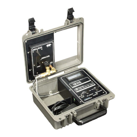
1.3 Enclosure The Model 2750 is a portable instrument housed in a rugged impact resistant NEMA 4X polyethylene enclosure which can easily be set up at the point of analysis and field-calibrated. The top of the case opens to reveal the operator interface panel. -
Page 13: Connections
2-pin connector located on the side of the unit. This signal is linear across the selected range and can be used to trigger alarms, record output or remote logging and data display. Figure 1-2: Gas Connections Figure 1-3: Electrical Connections Teledyne Analytical Instruments... -
Page 14: Operator Interface
Introduction Model 2750 1.5 Operator Interface The front panel contains the operator interface and is readily accessible after opening the enclosure. It is simple, consisting of an OFF/ON switch and two rotary switches—one for selecting between analysis or calibration modes and the other for selecting the particular analysis range to be employed during measurement. -
Page 15: Theory Of Operation
Turbine Generator Gas Analyzer Theory of Operation Theory of Operation The heart of the Model 2750 Turbine Generator Gas Analyzer is the compact thermal conductivity cell. It senses differences in thermal conductivity of the gas mixture and generates an output signal based on the thermal characteristics of the gas. - Page 16 The Model 2750 Turbine Generator Gas Analyzer is designed for analyzing the following binary gas mixtures and ranges: ...
-
Page 17: Electronics
Turbine Generator Gas Analyzer Theory of Operation 2.2 Electronics The Model 2750 uses a sophisticated miniature solid-state thermal conductivity sensor. This cell uses internal temperature compensation circuitry. It has both a reference and a measurement leg. The reference leg is driven by a constant current source and is used to heat the sensor’s substrate and to thermally compensate for ambient fluctuations. - Page 18 Theory of Operation Model 2750 width modulated (PWM) signal that is proportional to the gas concentration on that specific range. The PWM signal is passed through a low pass filter and is used to drive the display and the 0-1 VDC output signal (0.8 – 1VDC for the /Air range).
-
Page 19: Installation
Turbine Generator Gas Analyzer Installation Installation The Model 2750 is a portable unit and can easily be setup close to the analysis site. To ensure accuracy, however, the analyzer should be setup in such a manner as to avoid: Direct sunlight ... -
Page 20: Gas Connections
Installation Model 2750 shielded cable (nominally No. 22 wire size) between the analyzer output connector and the recording equipment. See Figure 3-1. Note: The signal output connector must be removed before closing the analyzer cover. Figure 3-1: Electrical Connections 3.2 Gas Connections Inlet gas connections are made at the gas control valve mounted on the upper panel. -
Page 21: Vent Line
3.2.2 Pressure Regulation All incoming gas lines from a high-pressure source should be equipped with pressure regulators. Pressure regulators should be installed as close to the sample take off point as possible to minimize sample line lag time. Teledyne Analytical Instruments... -
Page 22: Calibration
CAUTION: HIGH FLOW RATES CAN DAMAGE THE SENSOR. 3.3 Calibration The Model 2750 has been calibrated at the factory but will require periodic recalibration (zero and span). The calibration gases used to calibrate the instrument are: Zero:... -
Page 23: Zero Calibration Procedure
(see Figure 3-3) to the air/CO position for zeroing that range. Verify that the range selector switch is on the air/CO position. Figure 3-3: Interface Panel Showing Calibration Switch Position Teledyne Analytical Instruments... -
Page 24: Figure 3-4: Interface Panel Showing Calibration Switch Position
Installation Model 2750 Figure 3-4: Interface Panel Showing Calibration Switch Position 7. Use the air/CO zero trim pot to adjust the display to zero. See Figure 3-4 above. 8. Move the calibration switch to the H2/CO2 position and verify that the range selector switch is on H2/CO2. Use the H2/CO2 zero trim pot to adjust the display to zero. -
Page 25: Figure 3-6: Cal Switch In H2/Air Position
H2/air. See Figure 3-6 Figure 3-6: Cal Switch in H2/AIR Position 12. Use the H /air zero trim pot to zero that range by adjusting the pot until the display reads zero. See Figure 3-7 Figure 3-7: H2/AIR Zero Trimpot Teledyne Analytical Instruments... -
Page 26: Span Calibration Procedure
Please note that the 80-100% H in Air range is actually a 0-20% H Air range with the 2750 doing the simple calculation to report the reading as hydrogen purity. Thus the zero adjustment uses 100% air. The zero calibration is now complete, continue with a span calibration. -
Page 27: Figure 3-8: Range Switch In Air/Co2 Position
Set the flow between .5-1 SCFH. 8. Make sure the calibration switch is in the position then ANALYZE set the range switch to the H2/CO2 position. See Figure 3-10 Teledyne Analytical Instruments... -
Page 28: Figure 3-10: Range Switch In H2/Co2 Position
Installation Model 2750 Figure 3-10: Range Switch in H2/CO2 Position 9. Use the H span trim pot to adjust the display to 100% ±0.1%. See Figure 3-11 Figure 3-11: H2/CO2 Span Trimpot 10. Select The H2/Air range with the range selector switch. See... -
Page 29: Figure 3-13: H2/Air Span Trimpot
Please note that while the operating range of the analyzer is 80-100% H2 in Air, the electronics of the 2750 have been configured to allow for the use of 100% H2 span gas to calibrate this range to reduce the number of calibration gases that are required. - Page 30 Installation Model 2750 Teledyne Analytical Instruments...
-
Page 31: Setup And Operation
Attaching output cable Turning the instrument on and allowing it to warm up Prior to using the Model 2750, it must be calibrated on all three ranges. Refer to Section 3.3 for calibration procedures. Once the instrument is calibrated, it may be transported to the analysis site. -
Page 32: Operation
Setup and Operation Model 2750 Figure 4-1: Power and Output Connections to the Model 2750 The thermal conductivity sensor relies on a precise heat load to produce an accurate thermally compensated output signal. The sensor must be allowed to heat up and equilibrate before using the instrument for analysis. - Page 33 Note the changing concentration values until a steady reading is obtained (unless the sample gas stream concentration is changing). When the reading settles, the instrument is sufficiently purged. 6. Read the sample gas concentration from the display. Teledyne Analytical Instruments...
- Page 34 Setup and Operation Model 2750 Teledyne Analytical Instruments...
-
Page 35: Maintenance
If any part of the instrument malfunctions or fails to perform, the unit should be removed from service and returned for repair and calibration. The 2750 contains no user-serviceable parts. 5.1.1 Instrument Cleaning Use a damp cloth to wipe the instrument clean. -
Page 36: Troubleshooting
Maintenance Model 2750 If a leak detector is available, the model can be leak checked with the power off. Use helium and pressurize the lines to 1-5 psig and sniff all fittings and lines. If a leak detector is not available, admit air at 1-5 psig through the instrument lines. - Page 37 (d) Vent or sample in line is blocked. Remove constriction or blockage. Analyzer does not respond to (a) Incorrect instrument range sample gas selected. Select proper range for analysis. (b) Make sure CAL switch is in Analyze mode. (c) No sample flow—check flowmeter. Teledyne Analytical Instruments...
- Page 38 Maintenance Model 2750 Teledyne Analytical Instruments...
-
Page 39: Appendix
90-264 47-63 Hz VAC (US type 2 prong plug) Enclosure: NEMA 4X PET plastic housing Dimensions: (10.6 L x 4.8 H x 9.9 W)in (269.2 x 121.9 x 251.5) mm Operating Temp: 0-40°C Voltage output: 0-1VDC (0.8-1 VDC 80-100% range) Teledyne Analytical Instruments... -
Page 40: Spare Parts List
Appendix Model 2750 A.2 Spare Parts List PART NO DESCRIPTION A692 9 VDC POWER Adapter 90-264 VAC 47- 63Hz P1244 Trim Pot Tool ____________________ A minimum charge is applicable to spare parts orders. Note: Orders for replacement parts should include the part number (if available) and the model and serial number of the instrument for which the parts are intended.
Need help?
Do you have a question about the 2750 and is the answer not in the manual?
Questions and answers