Table of Contents
Advertisement
TB8220U
Commercial VisionPRO™
Programmable Thermostat
APPLICATION
The TB8220U Programmable Thermostat provides electronic control of 24 Vac heating and cooling systems.
See Table 1 for a description.
Feature
Powering Methods
• Battery only
• Direct connection to a 24 Vac transformer only
• Direct connection to a 24 Vac transformer with battery backup
System Types
• Conventional (up to 2 Heat, 2 Cool stages)
• Heat Pump (up to 3 Heat, 2 Cool stages)
Changeover
Manual or automatic changeover (selectable)
System Setting
Heat-Off-Cool-Auto
Fan Setting
Auto-On
MERCURY NOTICE
If this control is replacing a control that contains
mercury in a sealed tube, do not place your old
control in the trash. Dispose of properly.
Contact your local waste management authority
for instructions regarding recycling and the
proper disposal of an old control.
INSTALLATION
When Installing this Product...
1. Read these instructions carefully. Failure to follow
them could damage the product or cause a
hazardous condition.
2. Check ratings given in instructions and on the
product to ensure the product is suitable for your
application.
Table 1. TB8220U Thermostat Description.
INSTALLATION INSTRUCTIONS
Description
3. Installer must be a trained, experienced service
technician.
4. After installation is complete, check out product
operation as provided in these instructions.
CAUTION
Electrical Shock or Equipment Damage
Hazard.
Can shock individuals or short equipment
circuitry.
Disconnect power supply before installation.
Select Thermostat Location
Select a location for the thermostat about 5 ft (1.5m)
above the floor in an area with good air circulation at
average temperature. See Fig. 1.
62-3070-07
Advertisement
Table of Contents

Related Manuals for Honeywell VISIONPRO TB8220U


Summary of Contents for Honeywell VISIONPRO TB8220U
-
Page 1: Programmable Thermostat
TB8220U Commercial VisionPRO™ Programmable Thermostat INSTALLATION INSTRUCTIONS APPLICATION The TB8220U Programmable Thermostat provides electronic control of 24 Vac heating and cooling systems. See Table 1 for a description. Table 1. TB8220U Thermostat Description. Feature Description Powering Methods • Battery only •... -
Page 2: Wiring
TB8220U COMMERCIAL VISIONPRO™ PROGRAMMABLE THERMOSTAT 4. Remove the wallplate from the wall and drill two 3/16 in. holes in the wall (if drywall) as marked. For firmer material such as plaster, drill two 7/32 in. holes. Tap the wall anchors (provided) into the drilled holes until flush with the wall. - Page 3 TB8220U COMMERCIAL VISIONPRO™ PROGRAMMABLE THERMOSTAT 3. Insert the wires into the terminal block and tighten each screw terminal. See Fig. 5. WIRE WALLPLATE M19917 Fig. 5. Insert wires into terminal block. WALL OPENING 4. Push excess wire back into the wall opening and restrict wires to the shaded area.
-
Page 4: Conventional System Wiring
TB8220U COMMERCIAL VISIONPRO™ PROGRAMMABLE THERMOSTAT Conventional System Wiring (HOT) 24 VAC (HOT) 24 VAC OUTDOOR/INDOOR HEAT RELAY TEMPERATURE FAN RELAY SENSOR OUTDOOR/INDOOR ECONOMIZER TEMPERATURE COMPRESSOR CONTACTOR SENSOR POWER SUPPLY. PROVIDE DISCONNECT MEANS AND OVERLOAD HEAT RELAY PROTECTION AS REQUIRED. ECONOMIZER FACTORY INSTALLED JUMPER. - Page 5 TB8220U COMMERCIAL VISIONPRO™ PROGRAMMABLE THERMOSTAT (HOT) (HOT) 24 VAC 24 VAC OUTDOOR/INDOOR OUTDOOR/INDOOR FAN RELAY TEMPERATURE FAN RELAY TEMPERATURE SENSOR SENSOR COOL RELAY 2 COOL RELAY 1 HEAT RELAY 2 COOL RELAY 2 COOL RELAY 1 HEAT RELAY 2 (HOT) ECONOMIZER HEAT RELAY 1 ECONOMIZER...
-
Page 6: Heat Pump System Wiring
TB8220U COMMERCIAL VISIONPRO™ PROGRAMMABLE THERMOSTAT Heat Pump System Wiring (HOT) (HOT) 24 VAC 24 VAC FAN RELAY FAN RELAY OUTDOOR/INDOOR OUTDOOR/INDOOR TEMPERATURE TEMPERATURE COMPRESSOR CONTACTOR SENSOR COMPRESSOR CONTACTOR SENSOR CHANGEOVER VALVE CHANGEOVER VALVE ECONOMIZER AUXILIARY HEAT RELAY ECONOMIZER POWER SUPPLY. PROVIDE DISCONNECT MEANS AND OVERLOAD POWER SUPPLY. -
Page 7: Sensor Wiring For Temperature Averaging
TB8220U COMMERCIAL VISIONPRO™ PROGRAMMABLE THERMOSTAT Sensor Wiring for Temperature Averaging SUBBASE SUBBASE TR21 TR21 TR21 TR21-A TR21 TR21 TR21 M27481 THE TR21-A IS A 10K OHM SENSOR. M27483 Fig. 18. Wiring four TR21 (20K ohm) Sensors. Fig. 20. Wiring two TR21 (20K ohm) Sensors and one TR21-A (10K ohm) sensor to provide a temperature SUBBASE averaging network... -
Page 8: Power The Thermostat
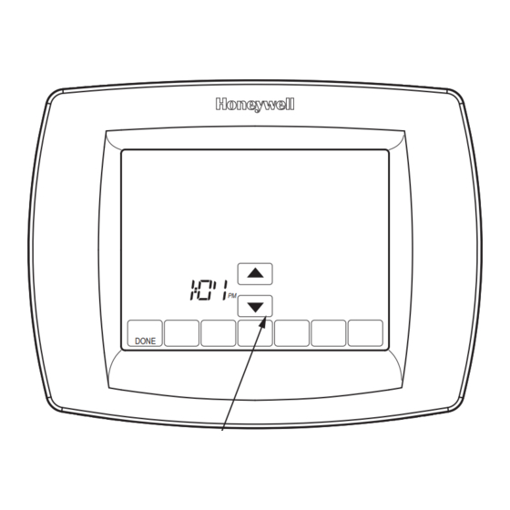
TB8220U COMMERCIAL VISIONPRO™ PROGRAMMABLE THERMOSTAT POWER THE THERMOSTAT You can choose from three methods to power the IMPORTANT thermostat: This tab must be removed in order to set the • Batteries only (AAA alkaline). real-time clock. • 24 Vac direct connection only. •... -
Page 9: Installer Setup Menu
TB8220U COMMERCIAL VISIONPRO™ PROGRAMMABLE THERMOSTAT Advanced Settings The thermostat has advanced settings to match the HVAC WALL system. These settings can be adjusted to match specific needs. Access to these settings is obtained as follows: 1. From the main screen, press SYSTEM. Five blank touch keys show on the bottom of the screen between DONE and CANCEL. - Page 10 TB8220U COMMERCIAL VISIONPRO™ PROGRAMMABLE THERMOSTAT Table 4. Installer Setup Menu. (Continued) Installer Setup Installer Setup Default Number Name Setting All Settings Notes 0170 System Selection 1—1H/1C Conv To use the Emergency Heat button, select setting 2—1H/1C HP #7 or #12. See Fig. 16 or 17 for auxiliary heat 3—1H w/o fan wiring.
- Page 11 TB8220U COMMERCIAL VISIONPRO™ PROGRAMMABLE THERMOSTAT Table 4. Installer Setup Menu. (Continued) Installer Setup Installer Setup Default Number Name Setting All Settings Notes 0340 Remote 0—None Averaging would not include on-board sensor. It is Temperature 1—Outdoor for Display accomplished by series/parallel combinations. Sensor 2—Outdoor for Control 2 applies only to Heat Pump applications (allowing...
-
Page 12: Operation
TB8220U COMMERCIAL VISIONPRO™ PROGRAMMABLE THERMOSTAT Table 4. Installer Setup Menu. (Continued) Installer Setup Installer Setup Default Number Name Setting All Settings Notes 0690 Temperature 1—Less Aggressive Only shown if system has cool stages. Control Cool 2—Standard Only integral gains affected. Affects control 3—More Aggressive operation in all control regimes (not just recovery or setpoint change). -
Page 13: Minimum-Off Timer Compressor Protection
TB8220U COMMERCIAL VISIONPRO™ PROGRAMMABLE THERMOSTAT Minimum-Off Timer Compressor 3. Choose appropriate Balance Point Temperature in Installer Setup Number 0350. Protection OPERATION IN HEAT MODE ABOVE BALANCE The thermostat has an adjustable Minimum-Off Timer that POINT (OUTDOOR TEMPERATURE) can be set from zero to five minutes (Factory Setting—five When the outdoor temperature is above the selected minutes). -
Page 14: Troubleshooting (Table 7)
TB8220U COMMERCIAL VISIONPRO™ PROGRAMMABLE THERMOSTAT TROUBLESHOOTING (TABLE 7) Table 7. Troubleshooting. Symptom Possible Cause Action Display does not come on. Thermostat is not being powered. Check for 24 Vac between C and Rc. Check that AAA batteries are installed correctly and are good. Temperature settings do not The upper or lower temperature limits Check temperature setpoints. - Page 15 TB8220U COMMERCIAL VISIONPRO™ PROGRAMMABLE THERMOSTAT Table 7. Troubleshooting. (Continued) Symptom Possible Cause Action Fan does not turn on in a call Fan Control in Heating is set to Gas or Set Fan Control in Heating to Electric for heat (electric furnace). Oil Furnace (Setting 0180).
-
Page 16: Specifications
Automation and Control Solutions Honeywell International Inc. 1985 Douglas Drive North Golden Valley, MN 55422 Honeywell Limited-Honeywell Limitée 35 Dynamic Drive ® U.S. Registered Trademark Toronto, Ontario M1V 4Z9 © 2011 Honeywell International Inc. 62-3070—07 M.S. Rev. 03-11 customer.honeywell.com Printed in U.S.A.
Need help?
Do you have a question about the VISIONPRO TB8220U and is the answer not in the manual?
Questions and answers