Honeywell TB6575 SuitePRO Installation Instructions Manual
Digital fan coil thermostats
Hide thumbs
Also See for TB6575 SuitePRO:
- Installation instructions manual (21 pages) ,
- Specification (4 pages) ,
- Quick manual (4 pages)
Table of Contents
Advertisement
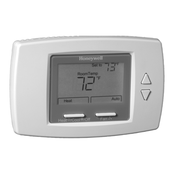
TB6575/TB8575 SuitePRO™
Digital Fan Coil Thermostats
PRODUCT DESCRIPTION
The SuitePRO™ is a family of Digital Fan Coil thermostats for
residential and commercial applications such as hotels,
condominiums, school classrooms, etc.
Three models are available for your application:
•
TB6575A1000 - 2-pipe or 4-pipe with seasonal/manual/
automatic heat/cool changeover; 120/240 Vac.
•
TB6575B1000 - 2-pipe only with seasonal or manual heat/
cool changeover; 120/240 Vac.
•
TB8575A1000 - 2-pipe or 4-pipe with seasonal heat/cool
changeover; 24Vac.
All three models are suitable for multiple applications. Changes
in output wiring and external links between wiring terminals
allow you to configure the thermostat for the appropriate
application.
The applications that are available are:
•
Heating or Cooling only
•
Two pipes: Heat or Cool with Manual Changeover
•
Two pipes: Heat or Cool with Seasonal Changeover
(requires optional pipe sensor)
•
Two pipes: Heat or Cool with Auxiliary Heat and Manual or
Seasonal Changeover (requires optional pipe sensor)
•
Four pipes: Mixed Manual and Auto Changeover
•
Four pipes: Manual Changeover
•
Four pipes: Auto Changeover
The fan is controlled from the thermostat. The Low, Mid, High, or
Auto fan settings are easily made with a press of a key.
Valves and auxiliary electric heaters can be controlled using a
relay or contactor controlled by the system switch.
INSTALLATION INSTRUCTIONS
FEATURES
•
Simple, intuitive user interface.
•
Pre-installed lead wires for fast installation (TB6575A
and TB6575B models only)
•
Backlight display permits easy viewing in any light.
•
Four buttons allow manual control of system operation,
fan speed, and temperature setpoint adjustment.
•
Digital display of ambient temperature, setpoint, heating
or cooling mode, fan status, and remote setback
•
Proportional plus Integral (P+I) control algorithm for
precision temperature regulation.
•
Adjustable deadband for auto changeover using the
Heat and Cool setpoint settings.
•
Adjustable maximum heating and minimum cooling
setpoint limits using range stops.
•
Installer Setup mode allows changes of operating
parameters.
•
EEPROM permanently retains user settings, including
setpoints, during power loss (no batteries required).
•
Selectable °C or °F display via Installer Setup.
•
Displayable pipe sensor temperature readout to aid in
troubleshooting.
•
Automatic pipe purge of five minutes, once every 24
hours, to ensure unrestricted flow (only when used with
optional pipe sensor).
•
Fan motor always begins on high speed to ensure
sufficient torque at startup.
•
Option to wire a remote indoor temperature sensor.
•
Freeze protect algorithm turns on heat when needed.
•
Energy Saving Options:
•
Activity Sensing- sets back thermostat to Economy
mode when there is no activity with the thermostat
(4, 12, or 24 hours selectable).
•
Remote Setback Inputs- receives dry contact input
from a time switch, occupancy sensor, or hotel card
key to set back thermostat to Economy mode.
•
Auto Fan Reset - eliminates the fan from being run
all the time by automatically setting the fan to Auto
(2 or 4 hour selectable).
•
VersaSpeed™ fan ramp algorithm automatically
adjusts fan speed (low, medium, and high).
Product Description ...................................................
Features ....................................................................
Specifications ............................................................
Ordering Information .................................................
Installation .................................................................
Setup .........................................................................
Operation .................................................................. 12
Troubleshooting ......................................................... 14
Contents
1
1
2
2
3
9
62-0278-01
Advertisement
Table of Contents

Subscribe to Our Youtube Channel
Related Manuals for Honeywell TB6575 SuitePRO


Summary of Contents for Honeywell TB6575 SuitePRO
-
Page 1: Table Of Contents
TB6575/TB8575 SuitePRO™ Digital Fan Coil Thermostats INSTALLATION INSTRUCTIONS FEATURES • Simple, intuitive user interface. • Pre-installed lead wires for fast installation (TB6575A and TB6575B models only) • Backlight display permits easy viewing in any light. • Four buttons allow manual control of system operation, fan speed, and temperature setpoint adjustment. -
Page 2: Specifications
TRADELINE® wholesaler or distributor, refer to the Accuracy ±5.0°F over the temperature sensing range TRADELINE® catalog or price sheets for complete ordering number. Orders can also be placed at http://customer.honeywell. Remote Setback Input: Dry contact, maximum resistance of com. -
Page 3: Installation
INSTALLATION TB6575/TB8575 SUITEPRO™ DIGITAL FAN COIL THERMOSTATS Dimensions Mounting and Wiring 1-1/8 5-13/16 (148) (29) CAUTION Equipment Damage Hazard. Operation at low temperatures can cause fan coil damage. 3-13/16 This thermostat is not a safety device. Do not use (97) it where the space temperature is outside of the device operating range. - Page 4 TB6575/TB8575 SUITEPRO™ DIGITAL FAN COIL THERMOSTATS INSTALLATION SUBBASE MOUNT SUBBASE TO HORIZONTAL 2X4 JUNCTION BOX USING TWO SCREWS SNAP MAIN BODY ONTO SUBBASE INSERT SCREW TO LOCK MAIN BODY TO SUBBASE M27590 Fig. 2. Mounting sub-base and thermostat to 2 x 4 in. junction box. MOUNT ADAPTOR PLATE ONTO ADAPTOR 4X4 WIRING BOX OR 2X4...
- Page 5 The fan coil thermostats are typically used with load relays to 24 VAC switch line voltage loads. Honeywell offers a convenient fan coil relay center, the W6380B1005, which provides 24 Vac power, three interlocked fan relays, and wiring center terminations for valve, relay and contactor loads.
- Page 6 Remote Temperature Sensor Wiring The TR21 is an optional remote temperature sensor that can be used as an alternative to the internal sensor. In addition to the TR21, other Honeywell sensors that use a 20k Ohm curve may TR21 TR21 be used as the remote sensor.
- Page 7 INSTALLATION TB6575/TB8575 SUITEPRO™ DIGITAL FAN COIL THERMOSTATS 120/240 Vac Wiring Diagrams (TB6575A/B) L (HOT) HEAT VALVE L (HOT) COOL VALVE HEAT VALVE REMOTE SENSOR REMOTE SENSOR REMOTE SETBACK REMOTE SETBACK M27570 Fig. 12. Four pipes (Heat and Cool) Manual/Auto Changeover M27566 wiring diagram (120/240 Vac shown).
- Page 8 TB6575/TB8575 SUITEPRO™ DIGITAL FAN COIL THERMOSTATS INSTALLATION 24 Vac Wiring Diagrams (TB8575) For the TB8575A1000 model, a 24 Vac Class 2 NEMA rated VALVE transformer must be used. HEAT VALVE (HOT) 24 VAC REMOTE SENSOR (HOT) REMOTE SETBACK 24 VAC PIPE SENSOR REMOTE SENSOR POWER SUPPLY.
-
Page 9: Setup
SETUP TB6575/TB8575 SUITEPRO™ DIGITAL FAN COIL THERMOSTATS SETUP The thermostat provides an LCD display, two buttons below the HEAT VALVE display for System and Fan control and two adjustment buttons COOL VALVE (Up and Down) to the right of the display. See Fig. 24. Settings, including setpoints, are permanently retained in EEPROM in case of a power outage. - Page 10 TB6575/TB8575 SUITEPRO™ DIGITAL FAN COIL THERMOSTATS SETUP Installer Setup (IS) Mode After the desired value displays, press the System button to store your value selection and display the next IS code. Installer Setup Mode allows you to configure the thermostat for your application.
- Page 11 SETUP TB6575/TB8575 SUITEPRO™ DIGITAL FAN COIL THERMOSTATS Table 4. Installer Setup (IS) Codes and Options. (Continued) Code Option Code Description Value Option Description (Default value shown in Bold) Notes CPH Value 1 to 12 Range is 1 to 12. Default is 4. The number selected indicates the for Heat maximum times Heating is cycled on...
-
Page 12: Operation
TB6575/TB8575 SUITEPRO™ DIGITAL FAN COIL THERMOSTATS OPERATION Table 4. Installer Setup (IS) Codes and Options. (Continued) Code Option Code Description Value Option Description (Default value shown in Bold) Notes Freeze Disabled; Default This feature can not activate when Protection the application is Cool only. Enabled –... - Page 13 OPERATION TB6575/TB8575 SUITEPRO™ DIGITAL FAN COIL THERMOSTATS Energy Saving Modes The fan ramping algorithm is illustrated in Fig. 28 ACTIVITY SENSING If Activity Sensing is enabled, any time the thermostat is not FAN SPEED IS HIGH touched (no single key is pressed) for the duration selected, the +4°F thermostat automatically falls back into the Unoccupied FAN SPEED IS MEDIUM...
-
Page 14: Troubleshooting
TB6575/TB8575 SUITEPRO™ DIGITAL FAN COIL THERMOSTATS TROUBLESHOOTING When the pipe sensor senses that the pipe temperature is out of NOTE: See “Auto Fan Reset” on page 13. limitation and needs to change over, the purging function will turn on for 5 minutes. TROUBLESHOOTING If the fan speed is set to Auto and purging is on, the fan turns on only when there is a call for Heat or Cool. - Page 15 TROUBLESHOOTING TB6575/TB8575 SUITEPRO™ DIGITAL FAN COIL THERMOSTATS Table 6. Troubleshooting. (Continued) Symptom Possible Cause Action Cooling does not turn on Cooling equipment failure. For TB6575A/B: (Cool On is solid in the Check for 120/240 Vac at the equipment between power and display).
-
Page 16: Customer Assistance
This warranty does not cover removal or reinstallation costs. This Scarborough, Ontario M1V4Z9. warranty shall not apply if it is shown by Honeywell that the defect or malfunction was caused by damage which occurred while the product was in the possession of a consumer.
Need help?
Do you have a question about the TB6575 SuitePRO and is the answer not in the manual?
Questions and answers