Advertisement
273 Branchport Avenue
Long Branch, NJ 07740
(800) 631-2148 (US)
(800) 397-5777 (CANADA)
www.wheelockinc.com
Use this product according to this instruction manual. Please keep this instruction manual for future reference.
GENERAL:
Wheelock's Series NS-24MCW Horn/Strobe requires only 2-wires for operation of the horn and strobe circuits and provides four selectable candela settings (15, 30, 75,
110). The NS-24MCW is the ideal choice for applications where the audible silence feature is required. The NS-24MCW is UL Listed under Standard 1971 for
Signaling Devices for the Hearing Impaired and UL Standard 464 for Audible Signal Appliances for indoor use only. The NS-24MCW is also ULC Listed under
Standard CAN/ULC-S526-02 for Visual Signaling Appliances and Standard CAN/ULC-S525-99 for Audible Signaling Appliances for Fire Alarm Systems. It is
molded with a strobe mounting plate (SMP) for use with a single-gang, double-gang, 4" backbox, 100mm European backbox or SHBB surface backbox (See wiring and
mounting information). This strobe model is Listed for wall mounting only. The NS-24MCW uses a xenon flashtube with solid state circuitry enclosed in a
polycarbonate lens to provide maximum visibility and reliability for effective visible signaling.
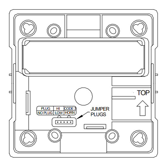
The horn portion of the NS-24MCW can be field set to provide either Continuous Horn or Code 3 Horn and can be field set for High (HI) or Low (LO) dBA.
NOTE: The Code 3 temporal pattern (1/2 second on, 1/2 second off, 1/2 second on, 1/2 second off, 1/2 second on, 1-1/2 off and repeat) is specified by ANSI and
NFPA 72 for standard emergency evacuation signaling. The Code 3 Horn should be used only for fire evacuation signaling and not for any other purpose.
The NS-24MCW Horn/Strobe can be used with a Sync Module (SM), Dual Sync Module (DSM) or Wheelock power supplies to provide synchronized strobe and
synchronized Code 3 signal.
This horn/strobe model is designed for use with either filtered DC (VDC) or unfiltered full-wave-rectified (VRMS) input voltage. All inputs are polarized for
compatibility with standard reverse polarity supervision of circuit wiring by a fire alarm control panel (FACP).
NOTE: All Canadian installations should be in accordance with the Canadian Standard for the Installation of Fire Alarm Systems - CAN/ULC-S524-01 and Canadian
Electrical Code, Part 1. Final acceptance is subject to authority having jurisdiction (AHJ).
WARNING:
PLEASE READ THESE INSTRUCTIONS CAREFULLY.
INSTRUCTIONS, CAUTIONS AND WARNINGS COULD RESULT IN IMPROPER APPLICATION, CANDELA SETTING, INSTALLATION AND/OR
OPERATION OF THESE PRODUCTS IN AN EMERGENCY SITUATION, WHICH COULD RESULT IN PROPERTY DAMAGE AND SERIOUS
INJURY OR DEATH TO YOU AND/OR OTHERS.
SPECIFICATIONS:
Model
NS-24MCW
Description
Continuous Horn
Code 3 Horn
ULC Directional Characteristics: Rated output 92dBA (Unit set on high volume and 24VDC)
-3dBA: 60 degrees left, 40 degrees right
NOTES:
1. The strobe will produce 1 flash per second over the "Regulated Voltage" range.
2. This horn/strobe model meets the required light distribution patterns defined in UL 1971 and ULC-S526-02.
3. This model is UL/ULC Listed for indoor use with a temperature range of +32°F to +120°F (0°C to +49°C) and maximum humidity of 93% ± 2% RH. The effect
of shipping and storage temperatures shall not adversely affect the performance of the appliance when it is stored in the original cartons and not subjected to
misuse or abuse.
WARNING: CANDELA SETTING WILL DETERMINE THE CURRENT DRAW OF THE PRODUCT.
DC
FWR
DC
FWR
When calculating the total current: Use Table 3 to determine the highest value of "RMS Current" for an individual NS then multiply the value by the total number of
NS Appliances. Be sure to add the currents for any other appliances powered by the same source and to include any required safety factors.
NOTE: The maximum number of strobes on a single notification appliance circuit shall not exceed 50.
CAUTION: These notification appliances are UL Listed as "Regulated". They are intended to be used with FACPs whose notification circuits are UL Listed as
"Regulated." These appliances shall not be used on UL Listed "Special Application" notification circuits unless the appliances are identified to be compatible in the
installation instructions of the FACP or unless the FACP is identified to be compatible in this instruction manual.
Copyright 2005 Wheelock, Inc. All rights reserved.
Thank you for using our products.
INSTALLATION INSTRUCTIONS
SERIES NS-24MCW MULTI-CANDELA HORN/STROBE
(WALL MOUNT VERSION)
Table 1: UL and ULC Ratings
Regulated
Voltage Range Limit
Voltage
Per UL 464 and UL 1971
(VDC/VRMS)
(VDC/VRMS)
24
16.0-33.0
Table 2: dBA Sound Output for 24VDC Per UL and ULC
Volume
Reverberant Per UL 464
16.0VDC
Low
77
High
83
Low
72
High
79
Table 3: Current Ratings (AMPS)
Maximum RMS Current with Hi dBA Setting
Regulated Voltage
16.0-33.0VDC
16.0-33.0VRMS
Maximum RMS Current with Low dBA Setting
Regulated Voltage
16.0-33.0VDC
16.0-33.0VRMS
FAILURE TO COMPLY WITH ANY OF THE FOLLOWING
Voltage Range Per CAN/ULC-S525-99
and CAN/ULC-S526-02
(VDC/VRMS)
20.0-31.0
Anechoic Per CAN/ULC-S525-99
24.0VDC
33.0VDC
20.0VDC
81
83
87
90
76
79
82
86
-6dBA: 70 degrees left, 70 degrees right
15cd
30cd
0.074
0.107
0.133
0.189
15cd
30cd
0.066
0.101
0.116
0.169
Strobe
Candela
(cd)
15/30/75/110
24.0VDC
31.0VDC
87
89
91
90
92
94
87
89
91
90
92
94
75cd
110cd
0.184
0.244
0.285
0.383
75cd
110cd
0.177
0.232
0.274
0.369
P83983 L
Sheet 1 of 4
Advertisement
Table of Contents

Related Manuals for Wheelock SERIES NS-24MCW


Summary of Contents for Wheelock SERIES NS-24MCW
- Page 1 GENERAL: Wheelock’s Series NS-24MCW Horn/Strobe requires only 2-wires for operation of the horn and strobe circuits and provides four selectable candela settings (15, 30, 75, 110). The NS-24MCW is the ideal choice for applications where the audible silence feature is required. The NS-24MCW is UL Listed under Standard 1971 for Signaling Devices for the Hearing Impaired and UL Standard 464 for Audible Signal Appliances for indoor use only.
- Page 2 3/4" conduit fittings are used. Although the limits shown for each mounting option comply with the National Electrical Code (NEC), Wheelock recommends use of the largest backbox option shown and the use of approved stranded field wires, whenever possible, to provide additional wiring room for easy installation and minimum stress on the product from wiring.
- Page 3 The 110 candela strobe setting is Listed for use in sleeping or non-sleeping areas when installed in accordance with appropriate NFPA Standards and the AHJ. WARNING: INSTALLATION OF WHEELOCK 110 CANDELA STROBE PRODUCTS IN SLEEPING AREAS SHOULD BE WALL MOUNTED AT LEAST 24"...
- Page 4 No part of the Series NS products and these instructions may be photocopied, printed or reproduced in any form or modified, adapted, changed or enhanced, or converted to another programming language, or used to create updated, related or derivative works, without the prior written consent of Wheelock. No part of the Series NS products shall be decomposed, disassembled or reverse engineered.
Need help?
Do you have a question about the SERIES NS-24MCW and is the answer not in the manual?
Questions and answers