Advertisement
Quick Links
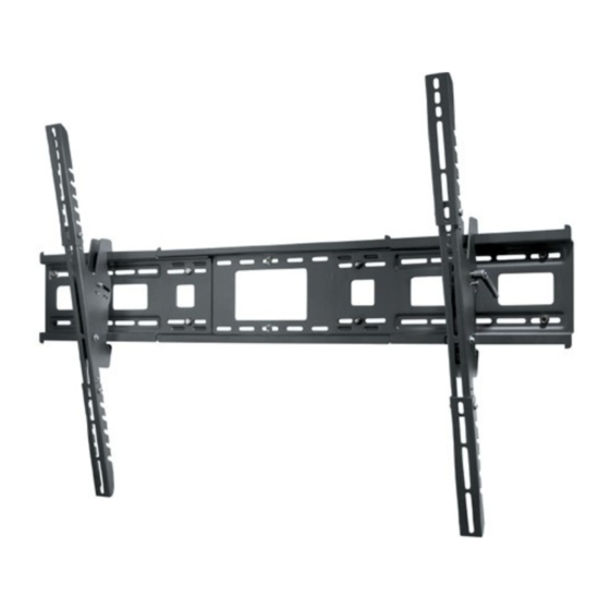
PWMT300
Installation and Assembly:
Universal Wall Mount
Model: PWMT300
Features:
• For flat panel screens
• One-touch tilt for effortless positioning and adjustment of the screen
• Ultra-slim design holds the screen flat against the wall
• IncreLok™ locking tilt positions for specific tilt settings in 5° increments
• BLACK. Scratch resistant fused epoxy finish.
• Mounts to wood studs, concrete, or to cinder blocks
NOTE:
Not for use with metal studs
Visit the Peerless Web Site at www.peerlessmounts.com
1 of 14
For customer care call 1-800-865-2112 or 708-865-8870.
This product is UL Listed. It must be
installed by a qualified professional
R
installer.
Max UL Load Capacity
ISSUED: 12-15-06 SHEET #:202-9189-1
250lb (113.5kg)
Advertisement

Related Manuals for LG PWMT300


Summary of Contents for LG PWMT300
- Page 1 PWMT300 Installation and Assembly: Universal Wall Mount Model: PWMT300 This product is UL Listed. It must be installed by a qualified professional installer. Features: Max UL Load Capacity 250lb (113.5kg) • For flat panel screens • One-touch tilt for effortless positioning and adjustment of the screen •...
-
Page 2: Table Of Contents
Note: Read entire instruction sheet before you start installation and assembly. WARNING • Do not begin to install this mount until you have read and understood the instructions and warnings contained in this Installation Sheet. If you have any questions regarding any of the instructions or warnings, please call Peerless customer care at 1-800-865-2112. -
Page 3: Parts List
Before you begin, make sure all parts shown are included with your product. Parts may appear slightly different than illustrated. Parts List Black Silver Description Qty. Part # Part# AA wall plate 201-1210 201-4210 BB left tilt bracket 201-0181 201-0192 CC right tilt bracket 201-0177 201-0193... -
Page 4: Adjusting Tilt Brackets
Adjustment of Extension Brackets Loosen four 1/4-20 x 1/4" screws on each adapter bracket (BB,CC). Position extension brackets, with slots facing downward, onto adapter brackets (BB,CC) at the appropriate position to accommodate your screen as shown in Figure 1.1. Securely tighten all 1/4-20 x 1/4" screws as shown in figure 1.2. NOTE: In all bracket extension positions, stops and 1/4-20 x 1/4"... -
Page 5: Installing Tilt Brackets
Installing Tilt Brackets Refer to Screen Compatibility Chart to determine the proper fasteners to use. NOTE: Refer to page 4 for adjustments of top extension bracket. To prevent scratching the screen, set a cloth on a flat, level surface that will support the weight of the screen. Place screen face side down. - Page 6 With tape measure, measure the outside to outside of the brackets on the back of your screen. If width of the tilt brackets on back of the screen is over 18-1/2" shown in figure 3.1, using a wrench, attach wing bracket (GG) to center bracket using two 1/4 serrated flanged locknuts (FF) as shown in figure 3.2.
-
Page 7: Installation To Double Wood Stud Wall
Installation to Double Wood Stud Wall WARNING • Installer must verify that the supporting surface will safely support the combined load of the equipment and all attached hardware and components. • Tighten wood screws so that wall plate is firmly attached, but do not overtighten. Overtightening can damage the screws, greatly reducing their holding power. -
Page 8: Installation To Triple Wood Stud Wall
Installation to Triple Wood Stud Wall WARNING • Installer must verify that the supporting surface will safely support the combined load of the equipment and all attached hardware and components. • Tighten wood screws so that wall plate is firmly attached, but do not overtighten. Overtightening can damage the screws, greatly reducing their holding power. -
Page 9: Installation To Solid Concrete Or Cinder Block
Installation to Solid Concrete or Cinder Block WARNING • When installing Peerless wall mounts on cinder block, verify that you have a minimum of 1-3/8" of actual concrete thickness in the hole to be used for the concrete anchors. Do not drill into mortar joints! Be sure to mount in a solid part of the block, generally 1"... -
Page 10: Mounting And Removal Of Flat Panel Screen
Mounting and Removing Flat Panel Screen WARNING BB and CC • Always use an assistant or mechanical lifting equip- ment to safely lift and position the plasma television. NOTE: For security, replace safety screw in each tilt bracket with M5 x 25 security screw (HH) using wrench (II). -
Page 11: Screen Compatibility Chart
See chart below to determine the fasteners to use with your screen. If your screen has a note in the far right column, then reference it on the last page. 23" 23LX1R multi none 23" 23LX2R multi none 23" 23LXRV multi none 23"... - Page 12 See chart below to determine the fasteners to use with your screen. If your screen has a note in the far right column, then reference it on the last page. 42" DU-42PZ60 multi 5.6mm ID 42" MP-42PZH12 multi 5.6mm ID 42"...
- Page 13 See chart below to determine the fasteners to use with your screen. If your screen has a note in the far right column, then reference it on the last page. 50" 50PC1DRA multi none 50" 50PC3D multi none 50" 50PM1M multi 5.6mm ID 50"...
- Page 14 NOTES (only pertains to the screen specified in the configuration chart) * The mount includes 12.7mm tall spacers 1 All hardware may not be included. If you are missing the additional fasteners needed for your screen, then please contact Customer Care at 1-800-865-2112. 2 If back of screen has a bumpout, or if mounting holes lie in pockets, then use M4 X 25 mm screw with 12.7mm tall spacers If screw gets less than 3 threads of engagement, then try the next longer length screw.