Advertisement
Quick Links
Advertisement

Related Manuals for LG PL-S860


Summary of Contents for LG PL-S860
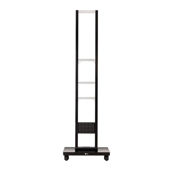
- Page 1 User Manual Single Digital Pillar Please read the Safety Precautions carefully before using this product. After reading this manual, please keep it in an easily accessible location for future reference. PL-S860 P/No: MFL69559213 (1609-REV01) *MFL69559213* Printed in Korea www.lg.com...
-
Page 2: Safety Precautions
SAFETY PRECAUTIONS Please read this manual carefully to properly install this product. After reading the manual, please keep it in an easily accessible location for future reference. WARNING • Follow the instructions in the manual to properly install this product. - Failure to follow the instructions in the manual can result in personal injury or product damage. -
Page 3: Assembly And Preparation
If the instructions in the manual are unclear, stop the installation process and contact the service center. • Check that the accessories provided with the product are all included before beginning installation. LG Electronics is not liable for any damage or loss of the accessories after the package has been opened. -
Page 4: Required Tools
Accessories Accessories are subject to change without prior notice to improve the performance of the product, and new accessories may be added as well. The illustrations in this manual may differ from the actual product and accessories. Fastening bracket x 2 Angle bracket screw Stand/Side/Back/Top Side cover screw... - Page 5 Assembly The images may differ from the actual product. WARNING • For safety, at least two people must work together to install the product. • Make sure to use gloves or other protective equipment during assembly for safety. Place the stand base on a flat surface. Place the pillar on the stand base, aligning it with the grooves in the base.
- Page 6 After placing the pillar in the indentation of the stand base, fix it in place using the two screws (M8 x L50) provided. Use the two screws (M8 x L15) provided to attach the angle brackets to the stand base. Repeat the steps for the rear stand bracket using the two screws (M8 x L15) provided.
- Page 7 Stick the double-sided tape on a power strip and fix it on the middle bar as shown in the image. Put the power cord of the power strip into the hole in the stand base. NOTE • Cut the double-sided tape to fit the size of the power strip. •...
- Page 8 Use the two screws (M4 x L12) provided to assemble the front stand bracket onto the stand base. Repeat the steps for the rear Stand Bracket using the two screws (M4 x L12) provided.
- Page 9 Lay a clean cloth on a flat floor, and then put the monitor set on it with the screen face down. Place the fastening brackets on the back of the monitor set, aligning them with the VESA holes. VESA hole Use the four screws (M8 x L15) provided and an L-wrench to attach the fastening brackets to the monitor set.
- Page 10 Place a soft cushion next to the pillar attached to the stand base. (Cushion size: At least 100 mm x 400 mm) Hold the assembled fastening brackets and use the cushion to set the monitor set upright.
- Page 11 Refer to the image below and make sure one person is holding the top of the monitor set while the other is holding the bottom panel, then lift it up. Use the brackets to hang the monitor set on the pillar. WARNING •...
- Page 12 Insert the IR cable into the hole in the stand base and attach it to the side of the stand. IR receiver...
- Page 13 Match the screw projection in the middle of the pillar to the hole in the middle of the side cover and fix it in place as shown in the image. Repeat the steps for the opposite side cover to attach it. Screw projection...
- Page 14 Fasten the 6 screws (M4 x L12) provided in the holes in the side cover. Repeat for the side cover on the opposite side.
- Page 15 Fix the sides of the side cover in place using the 6 screws (M4 x L12) provided. Repeat for the side cover on the opposite side. Stick the rubbers provided on the fastened side cover screws.
- Page 16 Attach the bottom back cover to the screw projection on the pillar as shown in the image. Screw projection...
- Page 17 Use the 10 screws (M4 x L12) provided to fix the bottom back cover in place. Attach the top back cover using the 10 screws (M4 x L12) provided.
- Page 18 Attach the top cover as shown in the image below by matching the screws on the pillar to the holes in the top cover. After attaching the top cover, fix it in place using the two screws (M4 x L12) provided.
-
Page 19: Product Specifications
PRODUCT SPECIFICATIONS 356.7 710.4 710.4 710.4 610.4 Model name PL-S860 Width (mm) 710.4 Height (mm) 2,328.8 Depth (mm) 610.4 Product weight (kg) 78.2 Product weight in package 115.3 (kg) - Page 20 The model name and serial number can be found on the back of the product. Contact your retailer for the applicable model. Please make a note of the following: Model name Serial No.
Need help?
Do you have a question about the PL-S860 and is the answer not in the manual?
Questions and answers