Table of Contents
Advertisement
Available languages
Available languages
Quick Links
Safety precautions
Follow these precautions to ensure safe installation and
mounting of your flat panel TV.
1.
Make sure these instructions are read and completely
understood before attempting installation. If you
are unsure of any part of this installation, contact a
LCD/Plasma TV Wall Mount
professional installer for assistance.
Installation Manual
2.
The wall or mounting surface must be capable of
supporting the combined weight of the wall mount and
the display; otherwise the structure must be reinforced.
Fits TVs 37"- 60"
3.
Protective eye wear and proper tools must be used.
A minimum of two people are required for this
Maximum Load Capacity – 165 lb (74.8 kg)
installation. Failure to use safety gear and/or attempting
this installation alone can result in property damage,
serious injury, or death.
4.
Follow all instructions and recommendations regarding
adequate ventilation and suitable locations for mounting
your display in the owner's manual for your display.
Be sure you have purchased the correct wall mount
for your TV. Recheck the size and weight constraints.
5.
Gather all necessary tools before you begin
installation. You will need a #3 bit Phillips screwdriver,
electric drill, drill bit (included), level (integrated level
on product), stud finder, and hammer (for brick and
MAF80BK
concrete installations).
6.
It is essential for the wall mount plate to be attached
Thank you for choosing the RCA MAF80BK Universal
to wall studs. (Use a stud finder.)
Flat Panel TV Wall Mount. This mount can be used for all
7.
Use the included hardware for mounting purposes.
major brands of 37" - 60" flat panel TVs, 165 lbs (74.8 kg) or
This hardware has been provided to ensure a safe and
under. This wall mount features a 0-15-degree tilt for easy
secure mount.
viewing. Before attempting to mount your television set,
please remove all parts from this package and read the
8.
Hire a licensed electrician to relocate an electrical
installation instructions carefully.
outlet, if needed.
9.
Be sure to purchase wires long enough to connect
WARNING: Use of this mount with a TV weighing
the TV to the audio and video components in your
over 165 lbs. or with a screen larger than 60" could
installation.
cause the mount to fail causing property damage and/or
personal injury.
10.
We recommend you hire a professional installer,
if you have any concerns about installing the TV
wall mount yourself.
Limited Lifetime Warranty
Keep your sales receipt to obtain warranty parts and
service and for proof of purchase. Attach it here and record
the model number. This number is located on the product.
Audiovox Electronics Corporation (the "Company") warrants to you the
original retail purchaser of this product that should it, under normal use
and conditions, be proven defective in material or workmanship during
Model No. __________________________________________
its lifetime while you own it, such defect(s) will be repaired or replaced (at
the Company's option) without charge for parts and repair labor.
To obtain repair or replacement within the terms of this Warranty, the
Purchase Date: ______________________________________
product is to be delivered with proof of warranty coverage (e.g. dated bill
of sale), specification of defect(s), transportation prepaid, to the Company
Dealer/Address/Phone ________________________________
at the address shown below. Do not return this product to the Retailer.
This Warranty does not cover product purchased, serviced or used
outside the United States or Canada.
This Warranty is not transferable and does not extend to costs incurred for
installation, removal or reinstallation of the product. This Warranty does
not apply if in the Company's opinion, the product has been damaged
through alteration, improper installation, mishandling, misuse, neglect,
or accident.
THE EXTENT OF THE COMPANY'S LIABILITY UNDER THIS
WARRANTY IS LIMITED TO THE REPAIR OR REPLACEMENT
PROVIDED ABOVE AND, IN NO EVENT, SHALL THE COMPANY'S
LIABILITY EXCEED THE PURCHASE PRICE PAID BY PURCHASER
Preparing to install
FOR THE PRODUCT.
This Warranty is in lieu of all other express warranties or liabilities. ANY
IMPLIED WARRANTIES, INCLUDING ANY IMPLIED WARRANTY
Before beginning the installation process, verify that you
OF MERCHANTABILITY OR FITNESS FOR A PARTICULAR PURPOSE
have all the necessary tools on hand. The following tools
SHALL BE LIMITED TO DURATION OF THIS WARRANTY. IN NO CASE
are required for proper installation:
SHALL THE COMPANY BE LIABLE FOR ANY CONSEQUENTIAL OR
INCIDENTAL DAMAGES WHATSOEVER. No person or representative is
authorized to assume for the Company any liability other than expressed
herein in connection with the sale of this product.
Tools
Some states/provinces do not allow limitations on how long an implied
#3 bit Phillips screwdriver
warranty lasts or the exclusion or limitation of incidental or consequential
damage so the above limitations or exclusions may not apply to you. This
Stud finder
Warranty gives you specific legal rights and you may also have other
rights which vary from state/province to state/province.
Electric drill
U.S.A.: Audiovox Electronics Corporation, 150 Marcus Blvd.,
Drill bit (included)
Hauppauge, New York 11788
CANADA: Audiovox Return Center, c/o Genco, 6685 Kennedy Road,
5/16" (8mm) masonry drill bit for concrete/
Unit 3, Door 16, Mississauga, Ontario L5T 3A5
brick installation
Trademark(s) Registered, Marques Deposee, Marcas Registradas.
Level (integrated level on product)
All other brands and product names are trademarks or registered
trademarks of their respective owners.
Hammer (for concrete installations)
© 2008 Audiovox Accessories Corporation
111 Congressional Blvd., Suite 350
Carmel, IN 46032
www.rca.com
MAF80BK_US_IB_00
Package Contents
Mounting the wall plate
Bag #
(Ref ) Item (Qty)
Drywall Installation
(A) M4x12 Bolt (x4)
1
(B) M4x30 Bolt (x4)
Important!
two adjacent wood studs no less than 16" apart.
(C) M4 Lock Washer (x4)
1.
Using a stud finder, locate and mark two adjacent studs
for securing the mount.
(D) M5x12 Bolt (x4)
2.
Place the wall plate against the wall and level it using
2
(E) M5x30 Bolt (x4)
the bubble guide.
3.
(F) M5 Lock Washer (x4)
Mark four locations (two per stud) on the wall where
the mount will be secured. Be sure to use the center of
each stud.
(G) M6x12 Bolt (x4)
4.
Remove the wall plate and drill a 1/4" (6 mm) pilot hole
3
(H) M6x35 Bolt (x4)
at each location using an electric drill.
5.
With the help of another person, replace the wall
(I) M6 Lock Washer (x4)
plate and level it using the bubble guide. Fix it to the
wall using the Lag Bolts (Q) and Lag Bolt Washers (R)
provided (Fig. 1).
(J) M8x16 Bolt (x4)
4
(K) M8x40 Bolt (x4)
(L) M8 Lock Washer (x4)
(M) Small Spacer (x4)
5
(N) Large Spacer (x4)
(O) M6 Washer (x4)
Fig. 1
Attach the wall plate to the wall.
(P) Concrete Anchor (x6)
6.
6
Do not over-tighten the bolts and do not release the
(Q) M8x63 Hex Bolt (x6)
wall plate until all screws are secure.
7.
Attach the cable manager to the middle of the top
(R) Hex Bolt Washer (x6)
crossbar (Fig. 2).
7
(S) Drill Bit (1)
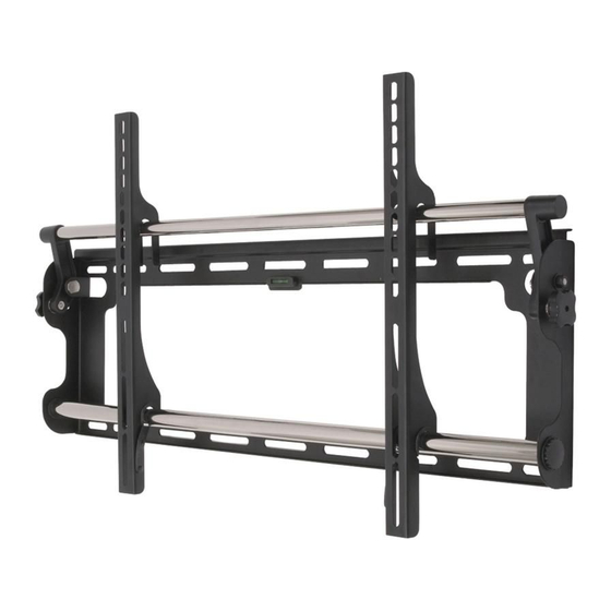
Product diagram
Adjustment Knobs
Integrated Bubble Level
Concrete/Brick Installation
1.
Place the wall plate against the wall and level it using
the bubble guide.
2.
With the help of another person, mark off six (6)
locations for fixing the mount to the wall.
3.
Place the wall plate aside and drill a hole at each
location using a 5/16" (8 mm) masonry bit. Remove any
excess dust from the holes.
4.
Insert one Concrete Anchor (P) into each hole. A
hammer can be used to lightly tap the anchors into
place if necessary.
5.
With the help of another person, replace the wall
plate and level it using the bubble guide. Fix it to the
wall using the Lag Bolts (Q) and Lag Bolt Washers (R)
provided (Fig. 1).
Padlock Hole
6.
(padlock not
Do not over-tighten the screws and do not release the
TV Mount Plate
included)
wall plate until all screws are secure.
Wall Mount Plate
7.
Security Lock Position
Attach the cable manager to the middle of the top
crossbar (Fig. 2).
Attaching the Arms to the TV
For safety, this mount must be secured to
1.
Examine the back of your television. If the back of your
display is flat, you will be using one of the shorter bolts
from the hardware kit. If the back of your display is
curved or recessed, you will be using one of the longer
bolts and a spacer (Fig. 4).
For displays with flat
backs...
the wall plate to the wall.
Fig. 4 - Use a longer bolt and spacer for displays with curved or recessed
Fig. 2
backs. Do not use the M6 Washer (O) if you are using the M8 Bolts (J or K).
Attach the
cable manager
2.
to the top
Determine the correct diameter bolt to use by trying
crossbar.
one bolt each from Bags 1 - 4 of the hardware kit. Do
not force any of the bolts – if you feel resistance stop
immediately to avoid damaging your display.
3.
Attach the arms to the back of your display
using the bolts identified in Steps 1 and 2 and the
corresponding Lock Washer (C, F, I, or L) (Fig. 4). You
will need to use the M6 Washers (O) if you are using
the M4, M5, or M6 bolts. If your display has a curved or
recessed back, you may also need to use a Spacer (M or
N).
4.
Make sure the screws are snug, but do not over-tighten.
Final Installation and
Adjustment
Fig. 3
Attach the arms to the back
of your display.
1.
With the help of another person, carefully lift your
display and place it on the wall plate (Fig. 5). Do not
release the display until the mounting arms have
securely hooked onto the crossbars!
Use extra
Important!
care during this part of the
installation. Avoid laying your
display face down if possible
as it may damage the viewing
surface.
Fig. 5
Fi 5
Carefully hook the
display onto the wall plate.
2.
Move the safety tab located on each arm into position
to avoid having the display accidentally lifted from the
mount. A padlock can be inserted into one of the tabs
to help prevent theft of your display (Fig. 6).
For displays with curved
or recessed backs...
3.
The cable manager can be used to keep your power
cord and other A/V cables in order.
4.
To adjust the tilt position, have one person hold the
display in position while another person loosens the
two tilt adjustment knobs located on either side of
the wall plate (Fig. 7). Once the knobs are loose, move
the display to the desired angle. Re-tighten the knobs
before releasing the display.
Specifications
Model:
MAF80BK
Two-piece, low-profile design
Description:
RCA Universal Flat Panel TV
Wall Mount
TV Size Range:
37" – 60"
Maximum Load:
165 lbs. (74.8kg)
Minimum Profile:
3.1" (7.9 cm)
Tilt:
+/- 0-15°
Universal VESA Compatibility
Integrated Bubble Level
Cord Management
Fig. 6
A small padlock
can be used to help
prevent theft of
your display
(padlock not
included).
Fig. 7
Loosen the
adjustment knobs
to change the tilt
angle. There is one
knob on each side
of the mount.
Advertisement
Table of Contents

Related Manuals for RCA MAF80BK


Summary of Contents for RCA MAF80BK
- Page 1 (M) Small Spacer (x4) It is essential for the wall mount plate to be attached prevent theft of Thank you for choosing the RCA MAF80BK Universal your display to wall studs. (Use a stud finder.) (padlock not Flat Panel TV Wall Mount.
- Page 2 Gracias por elegir el Montaje en Pared Universal para TV Necesitará un destornillador Phillips de punta #3, un de Panel Plano MAF80BK de RCA. Este montaje puede taladro eléctrico, una broca (incluida), un nivel (nivel (N) Separador grande (X4)
Need help?
Do you have a question about the MAF80BK and is the answer not in the manual?
Questions and answers