Table of Contents
Advertisement
Instruction
Manual
To learn more about Porter-Cable
visit our website at:
http://www.porter-cable.com
Copyright © 2003 PORTER-CABLE Corporation
ESPAÑOL: PÁGINA 23
FRANÇAISE : PAGE 43
Double Insulated
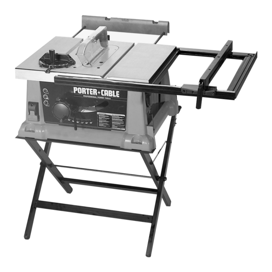
10" Bench Top Table Saw
MODEL 3812
Shown assembled with accessory stand model 38129
and accessory outfeed support model 38239.
Please make certain that the person who is to use
this equipment carefully reads and understands
these instructions before starting operations.
The Model and Serial No. plate is located on the main
housing of the tool. Record these numbers in the
spaces below and retain for future reference.
Model No. _____________________________________
Type __________________________________________
Serial No.______________________________________
IMPORTANT
Part No. 912933 - 09-15-03
Advertisement
Table of Contents

Related Manuals for Porter-Cable 3812


Summary of Contents for Porter-Cable 3812
- Page 1 Shown assembled with accessory stand model 38129 and accessory outfeed support model 38239. IMPORTANT Please make certain that the person who is to use To learn more about Porter-Cable this equipment carefully reads and understands visit our website at: these instructions before starting operations.
-
Page 2: Safety Guidelines - Definitions
If you have any questions relative to a particular application, DO NOT use the machine until you have first contacted Porter-cable to determine if it can or should be performed on the product. - Page 3 BEFORE OPERATING of accessories and attachments not recom- MACHINE. Learning the machine’s application, mended by Porter-Cable may cause damage to limitations, and specific hazards will greatly the machine or injury to the user. minimize the possibility of accidents and injury.
-
Page 4: Additional Safety Rules For Table Saws
ADDITIONAL SAFETY RULES FOR TABLE SAWS FAILURE TO FOLLOW THESE RULES MAY RESULT IN SERIOUS INJURY. 10. NEVER perform “free-hand” operations. Use either 1. DO NOT OPERATE THIS MACHINE until it is assembled and installed according to the the fence or miter gauge to position and guide the workpiece. -
Page 5: Power Connections
FOREWORD The Porter-Cable Model 3812 is a 10" Bench Top Table Saw. The saw comes with a 26"x20" table surface with a rip fence extension wing which provides a 24½" rip capacity for ripping 4x8 sheets. The Model 3812 comes with a Riptide™... -
Page 6: Carton Contents
CARTON CONTENTS Fig. 2 1. Saw 2. Fence 3. Table Insert 4. Blade Guard and Spreader Assembly 5. Blade Wrench (2) 6. Miter Gauge 7. Anchor Block Shim (3) 8. Handle 9. 1/4"-20x1-3/4" Screw... -
Page 7: Spreader Assembly
ASSEMBLY FOR YOUR OWN SAFETY, DO NOT CONNECT THE MACHINE TO THE POWER SOURCE UNTIL THE MACHINE IS COMPLETELY ASSEMBLED AND YOU READ AND UNDERSTAND THE ENTIRE INSTRUCTION MANUAL. BLADE RAISING AND LOWERING HANDWHEEL Insert the 1-3/4" screw (D) Fig. 4, through handle (E). Assemble handle (E) to handwheel (A) by threading screw (D) clockwise into handwheel as shown in Fig. -
Page 8: Miter Gage
6. NOTE: The anchor block (B) Fig. 6, has been adjusted at the factory so that the spreader will be aligned with the saw blade which is supplied with the saw. When changing to blades with different widths it may be necessary to adjust the anchor block (B) Fig. 9, as follows: 7. - Page 9 RIP FENCE TO SAW TABLE 1. The rip fence may be used on the right or left hand side of the saw table. Lift locking handle (A) Fig. 12, and position the front end of the fence on the front fence rail as shown.
-
Page 10: Operating Controls And Adjustments
To turn the saw “ON” pull the “ON/OFF” switch (A) out. To turn the saw “OFF”, push in on the “ON/OFF” switch (A). SOFT START Model 3812 has a “Soft Start” feature designed to minimize startup reaction torque. LOCKING SWITCH IN THE “OFF” POSITION Fig. -
Page 11: Rip Fence Operation And Adjustments
ADJUSTING 0 AND 45 DEGREE POSITIVE STOPS Your saw is equipped with positive stops for rapid and accurate positioning of the saw blade at 0 and 45 degrees to the table. This saw has the capability to go 2 degrees beyond 0 and 45 degrees (-2º to 47º). To adjust the positive stops, proceed as follows: DISCONNECT MACHINE FROM POWER SOURCE. -
Page 12: Rip Fence Extension
THE RIP FENCE MUST BE PARALLEL TO THE MITER GAGE SLOT AND SAW BLADE TO HELP PREVENT KICKBACK WHEN RIPPING. 4. The saw blade is set parallel to the miter gage slot at the factory and the fence must be parallel to the miter gage slot and saw blade in order to do accurate work and help prevent kickback when ripping. -
Page 13: Dust Port
MITER GAGE OPERATION AND ADJUSTMENTS When straight cross-cutting (blade set 90 degrees to the table) the miter gage can be used in either table slot. When bevel cross-cutting (blade tilted) only use the miter gage in the right table slot where the blade is tilted away from the miter gage and your hands. - Page 14 OPERATIONS Common sawing operations include ripping and cross-cutting plus a few other standard operations of a fundamental nature. As with all power tools, there is a certain amount of hazard involved with the operation and use of the tool. Using the tool with the respect and caution demanded as far as safety precautions are concerned, will considerably lessen the possibility of personal injury.
-
Page 15: Using Accessory Dado Head
If the ripped work is less than 4 inches wide, a PUSH STICK should always be used to complete the feed, as shown in Fig. 35. The PUSH STICK can easily be made from scrap material as explained in the section “CONSTRUCTING PUSH STICK.”... - Page 16 Fig. 39 Fig. 40 The dado head set (D) Fig. 40, is assembled to the saw arbor as shown. IMPORTANT: The blade guard and splitter assembly cannot be used when dadoing and must be removed. Auxiliary jigs, fixtures, push sticks and feather boards should also be used.
-
Page 17: Maintenance
AUTHORIZED PORTER-CABLE SERVICE STATION or a PORTER-CABLE SERVICE CENTER. At approximately 100 hours of use, take or send your tool to your nearest Authorized Porter-Cable Service Station to be thoroughly cleaned and inspected; worn parts replaced, when necessary, relubricated with fresh lubricant, if required;... -
Page 18: Constructing A Featherboard
ACCESSORIES A complete line of accessories is available from your Porter-Cable•Delta Supplier, Porter-Cable•Delta Factory Service Centers, and Porter-Cable Authorized Service Stations. Please visit our Web Site www.portercable.com for a catalog or for the name of your nearest supplier. Since accessories other than those offered by Porter-Cable•Delta have not been tested with this product, use of such accessories could be hazardous. -
Page 19: Constructing A Push Stick
CONSTRUCTING A PUSH STICK When ripping work less than 4 inches wide, a push stick should be used to complete the feed and could easily be made from scrap material by following the pattern shown. - Page 20 NOTES...
- Page 21 NOTES...
- Page 22 PORTER-CABLE LIMITED ONE YEAR WARRANTY Porter-Cable warrants its Professional Power Tools for a period of one year from the date of original purchase. We will repair or replace at our option, any part or parts of the product and accessories covered under this warranty which, after examination, proves to be defective in workmanship or material during the warranty period.
- Page 23 Porter-Cable • Delta products should be obtained by contacting any Porter-Cable • Delta Distributor, Authorized Service Center, or Porter-Cable • Delta Factory Service Center. If you do not have access to any of these, call 888-848-5175 and you will be directed to the nearest Porter-Cable •...
Need help?
Do you have a question about the 3812 and is the answer not in the manual?
Questions and answers