Table of Contents
Advertisement
Advertisement
Table of Contents

Related Manuals for ECS NFORCE3-A


Summary of Contents for ECS NFORCE3-A
- Page 3 Preface Copyright This publication, including all photographs, illustrations and software, is protected under international copyright laws, with all rights reserved. Neither this manual, nor any of the material contained herein, may be reproduced without written consent of the author. Version 1.0 Disclaimer The information in this document is subject to change without notice.
-
Page 4: Declaration Of Conformity
Declaration of Conformity This device complies with part 15 of the FCC rules. Operation is subject to the following conditions: • This device may not cause harmful interference, and • This device must accept any interference received, including interference that may cause undesired operation. Canadian Department of Communications This class B digital apparatus meets all requirements of the Canadian Interference-causing Equipment Regulations. -
Page 5: Table Of Contents
T T T T T ABLE OF CONTENTS ABLE OF CONTENTS ABLE OF CONTENTS ABLE OF CONTENTS ABLE OF CONTENTS Preface Chapter 1 Introducing the Motherboard Introduction....................1 Features.......................2 Motherboard Components...............4 Chapter 2 7 7 7 7 7 Installing the Motherboard Safety Precautions..................7 Choosing a Computer Case...............7 Installing the Motherboard in a Case............7... - Page 6 Integrated Peripherals..............35 Power Management Setup............40 PNP/PCI Configurations.............41 PC Health Status................42 Voltage Control................43 Load Optimized Defaults.............44 Set Supervisor/User Password............44 Save & Exit Setup Option.............45 Exit Without Saving..............45 Chapter 4 47 47 47 47 47 Using the Motherboard Software About the Software CD-ROM..............47 Auto-installing under Windows 98/ME/2000/XP........47 Running Setup................48 Manual Installation..................50...
-
Page 7: Introducing The Motherboard
Chapter 1 Introducing the Motherboard Introduction Thank you for choosing the NFORCE3-A motherboard. This motherboard is a high perfor- mance, enhanced function motherboard that supports Socket 754 AMD K8 processors for high-end business or personal desktop markets. The NFORCE3-A motherboard is based on NVIDIA™ NFORCE®3 250, which is a single- ™... -
Page 8: Features
Feature Processor This motherboard uses a 754-pin socket that carries the following features: • Accommodates AMD K8 processors • Supports HyperTransport interface for AMD K8 processors HyperTransport Technology is a point-to-point link between two devices, it enables integrated circuits to exchange information at much higher speeds than currently avail- able interconnect technologies. - Page 9 Onboard LAN (optional) The onboard LAN provides the following features: • Supports 10/100Mbps auto-negotiation • Supports half/full duplex operation • Supports MII/7-wire SNI (Serial Network Interface) interface • IEEE 802.3/802.3u compliant Integrated I/O The motherboard has a full set of I/O ports and connectors: •...
-
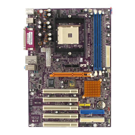
Page 10: Motherboard Components
Motherboard Components Introducing the Motherboard... - Page 11 Table of Motherboard Components LABEL COMPONENT 1 CPU Socket Socket 754 for AMD K8 processor 2 JCFAN1 CPU cooling fan connector 3 DIMM1~2 184-pin DDR SDRAM slots 4 FDD1 Floppy disk drive connector 5 JSFAN2 System fan connector 6 AGP1 Accelerated Graphics Port 7 JUSBV3 Power Source header...
- Page 12 Memo Introducing the Motherboard...
-
Page 13: Installing The Motherboard
Chapter 2 Installing the Motherboard Safety Precautions • Follow these safety precautions when installing the motherboard • Wear a grounding strap attached to a grounded device to avoid damage from static electricity • Discharge static electricity by touching the metal case of a safely grounded object before working on the motherboard •... -
Page 14: Checking Jumper Settings
Do not over-tighten the screws as this can stress the motherboard. Checking Jumper Settings This section explains how to set jumpers for correct configuration of the motherboard. Setting Jumpers Use the motherboard jumpers to set system configuration options. Jumpers with more than one pin are numbered. -
Page 15: Checking Jumper Settings
Checking Jumper Settings The following illustration shows the location of the motherboard jumpers. Pin 1 is labeled. Jumper Settings Jumper Type Setting (default) Description JCMOS1 3-pin 1-2: NORMAL CLEAR CMOS JCMOS1 2-3: CLEAR Before clearing the CMOS, make sure to turn the system off. -
Page 16: Connecting Case Components
Connecting Case Components After you have installed the motherboard into a case, you can begin con- necting the motherboard components. Refer to the following: Connect the CPU cooling fan cable to JCFAN1. Connect the case cooling fan connector to JSFAN2. Connect the case switches and indicator LEDs to the SW1. - Page 17 JCFAN1/JSFAN2: FAN Power Connectors Signal Name Function Ground Power +12V +12V Sensor FAN RPM rate sense JATXPWR1: ATX 20-pin Power Connector Signal Name Signal Name +3.3V +3.3V +3.3V -12V Ground Ground PS ON# Ground Ground Ground Ground Ground PW_OK Standby Voltage +5V +12V JATXWR2: ATX 12V Power Connector Signal Name...
-
Page 18: Front Panel Header
Front Panel Header The front panel header (SW1) provides a standard set of switch and LED headers commonly found on ATX or Micro ATX cases. Refer to the table below for information: Signal Function Signal Function HD_LED_P Hard disk LED+ FP PWR/SLP *MSG LED+ HD_LED_N Hard disk LED- FP PWR/SLP *MSG LED-... -
Page 19: Installing Hardware
Installing Hardware Installing the Processor Caution: When installing a CPU heatsink and cooling fan make sure that you DO NOT scratch the motherboard or any of the surface-mount resistors with the clip of the cooling fan. If the clip of the cooling fan scrapes across the motherboard, you may cause serious damage to the motherboard or its components. -
Page 20: Installing Memory Modules
CPU Installation Procedure The following illustration shows CPU installation components. Install your CPU. Pull up the lever away from the socket and lift up to 90-degree angle. Locate the CPU cut edge (the corner with the pin hold noticeably missing). Align and insert the CPU correctly. -
Page 21: Installation Procedure
Installation Procedure Refer to the following to install the memory modules. This motherboard supports unbuffered DDR SDRAM only. Push the latches on each side of the DIMM slot down. Align the memory module with the slot. The DIMM slots are keyed with notches and the DIMMs are keyed with cutouts so that they can only be installed correctly. - Page 22 Table A: Unbuffered DIMM Support for 754-pin Maximum DRAM 4.1. Numbers of DIMM 1 DIMM 2 Speed DIMMs single rank empty DDR400 DDR400 empty single rank DDR400 DDR400 double rank empty DDR400 DDR400 empty double rank DDR400 DDR400 single rank single rank DDR400 DDR400 double rank...
-
Page 23: Installing A Hard Disk Drive/Cd-Rom/Sata Hard Drive
Installing a Hard Disk Drive/CD-ROM/SATA Hard Drive This section describes how to install IDE devices such as a hard disk drive and a CD-ROM drive. About IDE Devices Your motherboard has a primary and secondary IDE channel interface (IDE1 and IDE2). An IDE ribbon cable supporting two IDE devices is bundled with the motherboard. - Page 24 About SATA Connectors Your motherboard features two SATA connectors supporting a total of two drives. SATA refers to Serial ATA (Advanced Technology Attachment) is the standard interface for the IDE hard drives which are currently used in most PCs. These connectors are well designed and will only fit in one orientation.
-
Page 25: Installing A Floppy Diskette Drive
Installing a Floppy Diskette Drive The motherboard has a floppy diskette drive (FDD1) interface and ships with a diskette drive ribbon cable that supports one or two floppy diskette drives. You can install a 5.25- inch drive and a 3.5-inch drive with various capacities. The floppy diskette drive cable has one type of connector for a 5.25-inch drive and another type of connector for a 3.5-inch drive. - Page 26 The AGP slot is used to install a graphics adapter that supports the 8X/4X AGP Slot AGP specification. It is AGP 3.0 compliant. This motherboard is equipped with five standard PCI slots. PCI stands for PCI1~5Slots Peripheral Component Interconnect and is a bus standard for expansion cards, which for the most part, is a supplement of the older ISA bus standard.
-
Page 27: Connecting Optional Devices
Connecting Optional Devices Refer to the following for information on connecting the motherboard’s optional devices: JAUDIO1: Front Panel Audio header This header allows the user to install auxiliary front-oriented microphone and line-out ports for easier access. Signal Name Signal Name Function AUD_MIC Front Panel Microphone input signal... - Page 28 JCDIN1: Analog Audio Input header Signal Name Function CD In left channel CD in_L Ground Ground CD In right channel CD in_R JSPDIF-OUT: SPDIF out header This is an optional header that provides an S/PDIF (Sony/Philips Digital Interface) output to digital multimedia device through optical fiber or coxial connector. Signal Name SPDIF OUT Ground...
-
Page 29: Connecting I/O Devices
IR1: Infrared port The mainboard supports an Infrared (IR1) data port. Infrared ports allow the wireless exchange of information between your computer and similarly equipped devices such as printers, laptops, Personal Digital Assistants (PDAs), and other computers. Signal Name Function Not Assigned Not assigned No pin... - Page 30 Memo Installing the Motherboard...
-
Page 31: Using Bios
Chapter 3 Using BIOS About the Setup Utility The computer uses the latest Award BIOS with support for Windows Plug and Play. The CMOS chip on the motherboard contains the ROM setup instructions for configuring the motherboard BIOS. The BIOS (Basic Input and Output System) Setup Utility displays the system’s configura- tion status and provides you with options to set system parameters. -
Page 32: Bios Navigation Keys
Press DEL to enter SETUP Pressing the delete key accesses the BIOS Setup Utility: Phoenix-AwardBIOS CMOS Setup Utility: Standard CMOS Features Voltage Control Advanced BIOS Features Load Optimized Defaults Advanced Chipset Features Set Supervisor Password Integrated Peripherals Set User Password Power Management Setup Save &... -
Page 33: Updating The Bios
Updating the BIOS You can download and install updated BIOS for this motherboard from the manufacturer’s Web site. New BIOS provides support for new peripherals, improvements in performance, or fixes for known bugs. Install new BIOS as follows: If your motherboard has a BIOS protection jumper, change the setting to allow BIOS flashing. -
Page 34: Standard Cmos Features
Standard CMOS Features This option displays basic information about your system. Phoenix-AwardBIOS CMOS Setup Utility Standard CMOS Features Date (mm:dd:yy) Thu, Jan. 20 2005 Item Help Time (hh:mm:ss) 9 : 33 : 26 IDE Channel 0 Master Menu Level IDE Channel 0 Slave IDE Channel 1 Master Change the day, month, IDE Channel 1 Slave... - Page 35 If you are setting up a new hard disk drive that supports LBA mode, more than one line will appear in the parameter box. Choose the line that lists LBA for an LBA drive. IDE Channel 0/1 Master/Slave Leave this item at Auto to enable the system to automatically detect and configure IDE devices on the channel.
-
Page 36: Advanced Bios Features
Advanced BIOS Features This option defines advanced information about your system. Phoenix-AwardBIOS CMOS Setup Utility Advanced BIOS Features Hard Disk Boot Priority [Press Enter] Item Help Virus Warning [Disabled] Quick Power On Self Test [Enabled] Menu Level Boot Up NumLock Status [On] Gate A20 Option [Fast]... - Page 37 Boot Up NumLock Status (On) This item defines if the keyboard Num Lock key is active when your system is started. Gate A20 Option (Fast) This item defines how the system handles legacy software that was written for an earlier generation of processors.
- Page 38 CPU Internal Cache (Enabled) All processors that can be installed in this mainboard use internal level 1 (L1) cache memory to improve performance. Leave this item at the default value for better perfor- mance. External Cache (Enabled) Most processors that can be installed in this system use external level 2 (L2) cache memory to improve performance.
-
Page 39: Advanced Chipset Features
Advanced Chipset Features These items define critical timing parameters of the motherboard. You should leave the items on this page at their default values unless you are very familiar with the technical specifications of your system hardware. If you change the values incorrectly, you may introduce fatal errors or recurring instability into your system. - Page 40 Min RAS# active time (Tras) (Auto) This item specifies the minumum RAS# active time. Row Precharge Time (Trp) (Auto) This item specifies the Row precharge to Active or Auto-Refresh of the same bank. Press <Esc> to return to the Advanced Chipset Features page. CPU OverClock in MHz (200) This item lets you select the CPU clock, the range is from 200MHz to 250MHz.
-
Page 41: Integrated Peripherals
Integrated Peripherals These options display items that define the operation of peripheral components on the system’s input/output ports. Phoenix-AwardBIOS CMOS Setup Utility Integrated Peripherals IDE Function Setup [Press Enter] Item Help Onboard Device [Press Enter] Super IO Device [Press Enter] Menu Level OnChip IDE Channel0 [Enabled]... - Page 42 Onboard Device (Press Enter) Scroll to this item and press <Enter> to view the following screen: Phoenix-AwardBIOS CMOS Setup Utility Onboard Device Item Help OnChip USB [V1.1+V2.0] USB KB/Storeage Support [Enabled] USB Mouse Support [Disabled] Menu Level Serial-ATA 2 (Internal PHY) [Enabled] AC97 Audio [Auto]...
- Page 43 SuperIO Device (Press Enter) Scroll to this item and press <Enter> to view the following screen: Phoenix-AwardBIOS CMOS Setup Utility SuperIO Device Item Help Onboard FDC Controller [Enabled] Onboard Serial Port 1 [3F8/IRQ4] Onboard Serial Port 2 [Disabled] Menu Level UART Mode Select Normal UR2 Duplex Mode...
- Page 44 SuperIO Device (Press Enter) Scroll to this item and press <Enter> to view the following screen: Phoenix-AwardBIOS CMOS Setup Utility SuperIO Device Item Help Onboard FDC Controller [Enabled] Onboard Serial Port 1 [3F8/IRQ4] Onboard Serial Port 2 [2F8/IRQ3] Menu Level UART Mode Select [IRDA] UR2 Duplex Mode...
- Page 45 OnChip IDE Channel0/1(Enabled) Use these items to enable or disable the PCI IDE channels that are integrated on the mainboard. Primary/Secondary Master/Slave PIO (Auto) Each IDE channel supports a master device and a slave device. These four items let you assign the kind of PIO (Programmed Input/Output) was used by the IDE devices.
-
Page 46: Power Management Setup
Power Management Setup This option lets you control system power management. The system has various power- saving modes including powering down the hard disk, turning off the video, suspending to RAM, and software power down that allows the system to be automatically resumed by certain events. -
Page 47: Pnp/Pci Configurations
button down for four seconds to cause a software power down. WOL (PME#) From Soft-Off (Disabled) This item allows you to enable or disable the Wake on Lan function. WOR (RI#) From Soft-Off (Disabled) This item allows you to enable or disable the Wake on Ring signal function. Power-On by Alarm (Disabled) This item allows users to enable or disable the alarm to wake up the system. -
Page 48: Pc Health Status
• IRQ Resources [Press Enter]::In the IRQ Resources submenu, if you assign an IRQ to Legacy ISA, then that Interrupt Request Line is reserved for a legacy ISA expansion card. Press <Esc> to close the IRQ Resources submenu. In the Memory Resources submenu, use the first item Reserved Memory Base to set the start address of the memory you want to reserve for the ISA expansion card. -
Page 49: Voltage Control
Voltage Control On motherboards that support hardware monitoring, this item lets you monitor the parameters for critical voltages. Phoenix-AwardBIOS CMOS Setup Utility Voltage Control CPU Voltage [Default] Item Help DDR Voltage [Defaclt] Menu Level : Move Enter: Select +/-/PU/PD:Value F10:Save ESC:Exit F1: General Help F5:Previous Values F7:Optimized Defaults CPU/DDR Voltage (Default) -
Page 50: Load Optimized Defaults
Load Optimized Defaults This option opens a dialog box that lets you install optimized defaults for all appropriate items in the Setup Utility. Press <Y> and then <Enter> to install the defaults. Press <N> and then <Enter> to not install the defaults. The optimized defaults place de- mands on the system that may be greater than the performance level of the components, such as the CPU and the memory. -
Page 51: Save & Exit Setup Option
Save & Exit Setup Highlight this item and press <Enter> to save the changes that you have made in the Setup Utility and exit the Setup Utility. When the Save and Exit dialog box appears, press <Y> to save and exit, or press <N> to return to the main menu. Exit Without Saving Highlight this item and press <Enter>... - Page 52 Memo Using BIOS...
-
Page 53: Using The Motherboard Software
Chapter 4 Using the Motherboard Software About the Software CD-ROM The support software CD-ROM that is included in the motherboard package contains all the drivers and utility programs needed to properly run the bundled products. Below you can find a brief description of each software program, and the location for your motherboard version. -
Page 54: Running Setup
Setup Tab Setup Click the Setup button to run the software installation program. Select from the menu which software you want to install. Browse CD The Browse CD button is the standard Windows command that allows you to open Windows Explorer and show the contents of the support Before installing the software from Windows Explorer, look for a file named README.TXT, INSTALL.TXT or something similar. - Page 55 Click Next. The following screen appears: Check the box next to the items you want to install. The default options are recommended. Click Next run the Installation Wizard. An item installation screen appears: Follow the instructions on the screen to install the items. Drivers and software are automatically installed in sequence.
-
Page 56: Manual Installation
Manual Installation Insert the CD in the CD-ROM drive and locate the PATH.DOC file in the root directory. This file contains the information needed to locate the drivers for your motherboard. Look for the chipset and motherboard model; then browse to the directory and path to begin installing the drivers.
Need help?
Do you have a question about the NFORCE3-A and is the answer not in the manual?
Questions and answers