Advertisement
Advertisement
Table of Contents

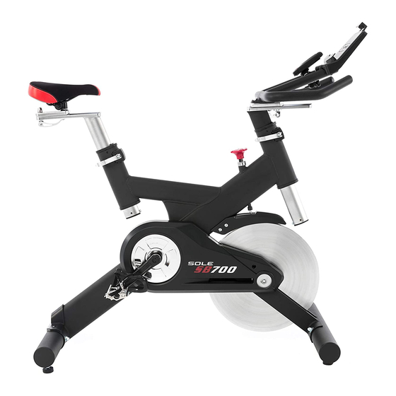
Summary of Contents for SOLE SB700
- Page 1 PLEASE CAREFULLY READTHIS ENTIRE MANUAL BEFORE OPERATING YOUR NEW Indoor cycle...
- Page 2 TA LE OF T TS Product Registration Important Safety Instruction_ Important Operation Instructions SB700 Assembly Instructions Operation of Your New Indoor Cycle Manufacturer's Limited Warranty ATTENTION THIS INDOOR CYCLE IS INTENDED FOR RESIDENTIAL USE ONLY AND IS WARRANTED THE APPLICATION.
- Page 3 SOLE will do all we can to make your ownership experience as pleasant as possible for many years to come. If you have any questions about...
- Page 4 Failure to follow all guidelines may compromise the effectiveness of the exercise experience, expose yourself (and possibly others) to injury, and reduce the longevity of the equipment. SAVE THESE INSTRUCTIONS =THINK SAFETY! SB700 INDOOR CYCLE...
- Page 5 Proper installation and regular maintenance are required to ensure user's safety. Maintenance is the sole responsibility of the owner. SB700 INDOOR CYCLE...
- Page 6 ASSEM LY PACK C HECKLIST #82.3/8" #81.3/8"x 3-1/2" #83.3/8"x 23mm Nut (4 pcs) Button Head Socket Bolt (4 pcs) Flat Washer (4 pcs) #91.M5x lOmm Screw (2 pcs) #49.5/16" #48.5/16"x 16mm #88.5/16"x 15mm Split Washer (4 pcs) Flat Washer (4 pcs) Screw (4 pcs) #85.
- Page 7 & Rear floor stabilizer tubes by inserting two Button Head Socket Bolts (81) through each tube. Fasten two Curved Washers (83) and two Nuts (82) on each tube using the wrench (85) provided. SB700 INDOOR CYCLE...
- Page 8 REAR STABILIZER COVER #91.M5 x lOmm Screw (2 pcs) -.,\ -.,\ -.,\ -.,\ -.,\ -.,\ Attach the Rear Stabilizer cover with two Screws (91).Tighten using the Combination M5 Allen Wrench & Phillips Head Screw Driver (86). 1 - Console 2 - Mounting Clamp 3 - Clamp mounting screw 4 - Clamping thumb screw 5 - Velcro...
-
Page 9: Battery/Console/Transmitter Installation
Sole indoor Cycling Console Battery installation: Remove the battery cover from the back of the computer. Insert 2 AAA batteries into the battery compartment and reinstall the battery cover. When Battery working voltage is too low, The "Low battery" indicator... - Page 10 #49. 5/16" Split Washer (4 pcs) #48. 5/16"x 16mm Flat Washer (4 pcs) #88. 5/16"x lSmm Screw (4 pcs) Attach the handlebars (make sure they are oriented as in the illustration) with four Screws (88), four Split Washers (49), and four Flat Washers (48). Tighten firmly using the Combination M5 Allen Wrench &...
-
Page 11: Left/Right Pedals
Tighten each pedal as firmly as possible with the Wrench (85) provided. If you here a thumping sound when you are pedaling, this usually means one or both pedals are loose.You may need to retighten them after use. SB700 INDOOR CYCLE... - Page 12 CLOCK PLEASE NOTE: The Sole Indoor Cycling Console system is designed as a sealed unit and not meant to be opened other than for the sole purpose of installing batteries. Any opened units will void the warranty. To clean the Sole Indoor Cycling Console use a clean damp cloth. Use of any caustic cleaning solutions will void the warranty.
-
Page 13: Console Operation
CONSOLE OPERATION TIME Time is measured in min:sec.There is a time of day clock and a workout timer clock.The workout time will count up or count down during pedaling. If pedaling stops, the time will stop counting after 3sec. RPM/CADENCE Cadence is the measurement of how fast the cranks are rotating... -
Page 14: Mode Select
Press the right hand key to increase maxi- mum heart rate limit. After setting the max- imum heart rate, press the left hand key to adjust the minimum heart rate limit. SB700 INDOOR CYCLE... - Page 15 H EART RATE TARGET ZON ES I. GENDER: Press the left hand key until SPEED is displayed, then press the right hand key for 3 seconds.The TIME will be flashing, press the left hand key until the gender icon is blinking. Press the right hand key to select gender.
-
Page 16: First Time User Instructions
A suitable forward/aft position should allow the rider to comfortably grasp the handlebar with a slight bend at the elbow. Tighten the quick release to secure the handlebar assembly. SB700 INDOOR CYCLE... -
Page 17: Dual Function Pedal
Adjust forward and backward via the slots in the shoe sole. Adjust laterally via play between cleat washer and cleat.Tighten cleats very firmly. Cleat position... -
Page 18: Basic Operation
To apply the brake, press down on the tension knob. Before dismounting, apply the brake to stop flywheel, or increase resistance and let flywheel come to a stop. SB700 INDOOR CYCLE... -
Page 19: Troubleshooting
If they are found to be worn internally, recommend replacing the pedal. Use of lubricants or cleaning solutions other than those so specified will result in diminished performance and a shorter life span for that part. SB700 INDOOR CYCLE... - Page 20 Products that do not have a warranty registration card on file at SOLE. SOLE reserves the right to request proof of purchase if no warranty record exists for the product.


Need help?
Do you have a question about the SB700 and is the answer not in the manual?
Questions and answers