MTD 300 Series Operator's Manual
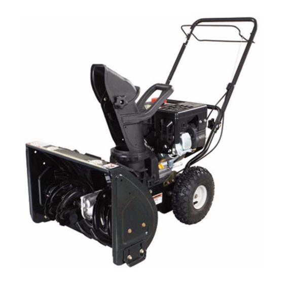
Two-stage snow thrower
Hide thumbs
Also See for 300 Series:
- Operator's manual (52 pages) ,
- Shop manual (44 pages) ,
- Owner's manual (20 pages)
Table of Contents
Advertisement
Available languages
Available languages
Advertisement
Table of Contents

Related Manuals for MTD 300 Series


Summary of Contents for MTD 300 Series
- Page 1 Safe Operation Practices • Set-Up • Operation • Maintenance • Service • Troubleshooting • Warranty Two-Stage Snow Thrower m 300 Series MTD LLC, P.O. BOX 361131 CLEVELAND, OHiO 44136-0019 PrintedIn USA FormNo.769-03940 (April 24,2008)
-
Page 2: Record Product Information
Choose from the options below: Visit us on the web at www.mtdproducts.com Call a Customer Support Representative at (800) 800-7310 or (330) 220-4683 Write us at MTD LLC • RO. Box 361131 • Cleveland, OH • 44136-0019... -
Page 3: Important Safe Operation Practices
ImportantSafeOperation Practices WARNING! This symbol points out important safety instructions which, if not followed, could endanger the personal safety and/or property of yourself and others. Read and follow all instructions in this manual before attempting to operate this machine. Failure to comply with these instructions may result in personal injury. - Page 4 Never run an engine indoors or in a poorly ventilated area. SafeHandling of Gasoline Engine exhaust contains carbon monoxide, an odorless To avoid personal injury or property damage use extreme care and deadly gas. in handling gasoline. Gasoline is extremely flammable and the Do not operate...
-
Page 5: Maintenance And Storage
Maintenance & Storage Do not modify engine Never tamper with safety devices. Check their proper To avoid serious injury or death, do not modify engine in any operation regularly. Refer to the maintenance way. Tampering with the governor setting can lead to a runaway adjustment sections of this manual. -
Page 6: Safety Symbols
Safety Symbols This page depicts and describes safety symbols that may appear on this product. Read, understand, and follow all instructions on the machine before attempting to assemble and operate. READ THE OPERATOR'S MANUAL(S) Read, understand, and follow all instructions in the manual(s) before attempting assemble and operate... -
Page 7: Assembly And Setup
Assembly & Set-Up Contentsof Carton One Snow Thrower Two Replacement Auger Shear Pins One Chute Assembly One Product Registration Card One Snow Thrower Operator's Manual Assembly Setting UpThe Handle Remove cable tie (if present) securing upper handle to lower handle for shipping purposes. - Page 8 TirePressure Set-Up The proper inflation pressure is between 15 psi and 20 psi. Check ShearPins the tire pressure periodically and maintain equal pressure in A pair of replacement auger shear pins and bow tie cotter pins both tires at all times. Excessive pressure (well above 20 psi) may are included with your snow thrower.
- Page 9 NOTE: Do not overfill. Overfilling with oil may result in engine smoking, hard starting or spark plug fouling. Replace and tighten cap/dipstick firmly before starting engine. Adjustments Skid Shoe Fuel Level Indicator The snow thrower skid shoes are adjusted upward at the factory Top View for shipping purposes.
- Page 10 NOTE: If the auger shows ANY signs of rotating, immediately DischargeChute return to the operator's position and shut off the engine. Wait for Loosen the wing knob on the upper chute, adjust chute all moving parts to stop before adjusting the auger control cable and chute control to desired operating...
-
Page 11: Controls And Features
Controls a nd Features Auger Control Drive Control Starter Rope FuelCap UpperChute Fuel C ap Chute Assembly Muffler Recoil Starter Handle Clean-out Tool Oil Cap ChuteKnob Auger ShavePlate OilDrain SkidShoe Figure 4-1 DriveControl ChuteAssembly Located on the underside of the upper handle, the drive control Snow drawn into the auger housing is discharged out of the... - Page 12 Chute Handle ThrottleControl The direction of snow throwing corresponds to the direction The throttle control is located on the rear of the engine. of the chute opening. Use the chute handle to turn the chute regulates the speed of the engine and will shut offthe engine assembly...
-
Page 13: Operation
Operation Pull gently on the starter handle until it begins to Starting the Engine resist, then pull quickly and forcefully to overcome compression. Do not release the handle and allow it to snap back. Return rope SLOWLY to original position. moving parts. - Page 14 ReplacingShearPins The augers are secured to the spiral shaft with two shear pins and cotter pins. If the auger should strike a foreign object or ice jam, the snow thrower is designed so that the pins may shear. If the augers will not turn, check to see if the pins have sheared. See Fig.
-
Page 15: Maintenance And Adjustments
Maintenance& Adjustments ShavePlate and Skid Shoes Maintenance The shave plate and skid shoes on the bottom of the snow General Recommendations thrower are subject to wear. These should be checked Always observe safety rules when performing any type of periodically and replaced when necessary. - Page 16 Lubrication Preparing TheEngine Lubricate pivot points on the auger control and drive in the tank indoors or in poorly ventilated areas, control with a light engine oil once a season, see Fig. 6-2. WARNING! where fuel fumes may reach an open flame, spark or Never store the snow thrower with fuel pilot light as on a furnace, water heater, clothes...
-
Page 17: Engine Maintenance
Engine Maintenance WARNING! To prevent accidental start-up, shut off Periodic inspection and adjustment of the engine is essential high level performance is to be maintained. Regular maintenance the engine and remove the ignition key before will also ensure a long service life. The required service intervals performing any type of engine... -
Page 18: Spark Plug
Check that the spark plug washer is in good condition Spark Plug and thread the spark plug in by hand to prevent cross- threading. plug removed. DO NOT crank engine with spark After the spark plug is seated, tighten with a spark plug WARNING! DO NOT check for spark with spark plug removed. -
Page 19: Servicing Augers
Service Servicing Augers AugerBelt The augers are secured to the spiral shaft with four shear pins and IMPORTANT: Gas could leak from the carburetor at this point, cotter pins. If you hit a foreign object or ice jam, the snow thrower the gas cap should have been covered with plastic as previously instructed. -
Page 20: Drive Belt
Pivot the transmission forward to release pressure on the Drive Belt drive belt. Remove belt from transmission pulley. NOTE.: Replace the drive belt before reassembling the new auger Remove the drive belt from around the engine pulley, and belt. away from the unit. Tip the snow thrower up and forward so that it rests on the... -
Page 21: Troubleshooting
Troubleshooting Problem Cause Remedy Engine runs erratic 1. Unit running on choke. 1. Move choke lever to OFF position. 2. Fuel line blocked, or stale fuel. 2. Clean fuel line and fill tank with fresh, clean gasoline. 3. Water or dirt in fuel system. 3. -
Page 22: Replacement Parts
Replacement P arts Component Part Number and Description 731-2643 Chute Clean-out tool 784-5580 Skid Shoe, Standard 738-04124A Shear Pin 714-04040 Bow-tie Cotter Pin 790-00117 Shave Plate 954-04014 Auger Drive Belt 954-04013 Wheel Drive Belt 751-10630 951-10292 Champion F6RTC Resistor Spark Plug Phone (800) 800-7310 to order replacement parts or a complete Parts Manual (have your full model... - Page 23 MTD. OWNER'S WARRANTY RESPONSIBILITIES: As the smalloff-roadengineowner,youare responsible forthe performance of the requiredmaintenance listed in your Owner'sManual.MTD recommends that you retainall yourreceiptscoveringmaintenances on yoursmall off-roadengine,but MTDcan not denywarrantysolelyfor the lack of receiptsor foryour failureto ensurethe performanceto all scheduledmaintenance. As the smalloff-roadengineowner,youshouldhoweverbe awarethat MTDmaydenyyour warrantycoverageif yoursmall off-roadengine or part hasfaileddue toabuse, neglect,impropermaintenance or unapprovedmodifications.
- Page 24 (8)Throughout the engine's warranty period defined inSubsection (a)(2), MTD will m aintain a supply ofwarranted parts s ufficient tomeet the expected demand forsuch parts. (9)Any replacement part m ay b eused i ntheperformance...
-
Page 25: Limited Warranty
MANUFACTURER'S LiMiTED WARRANTY The limited warranty set forth below is given by MTD LLC with c. Service completed by someone other than an authorized service dealer. respect to new merchandise purchased and used in the United States and/or its territories and possessions, and by MTD Products Limited d. - Page 26 Medidas importantes de seguridad • Configuraci6n • Funcionarniento • Mantenimiento • Servicio • Soluci6n de problemas • Garantia ANUAL M_quina quitanieve de dos etapas m Serie 300 MTD LLC, P.O. BOX 361131 CLEVELAND, OHiO 44136-0019 Impresoen Estados UnidosdeAm_rka...
- Page 27 Elija entre las opciones que se presentan a continuaci6n: Visite nuestro sitio web en www.troybilt.com Llame a un representante de Asistencia al CIiente al (800) 828-5500 6 (330) 558-7220 Escribanos a MTD LLC • P.O. Box 361131 • Cleveland, OH • 44136-0019...
-
Page 28: Medidas Importantes De Seguridad
Medidasimportantes de seguridad ADVERTENCIA: La presencia de este s[mbolo indica que se trata de instrucciones importantes de seguridad que se deben respetar para evitar poner en peligro su seguridad personal y/o material y la de otras personas. Lea y siga todas las instrucciones de este manual antes de poner en funcionamiento esta m_quina. - Page 29 Nunca opere la m_iquina si falta un montaje del canal o si Manejo seguro de la gasolina el mismo est,1 dahado. Mantenga todos los dispositivos Para evitar lesiones personales o da_os materiales tenga mucho seguridad en su lugary en funcionamiento. cuidado cuando trabaje con gasolina.
- Page 30 Mantenimientoy AImacenamiento Nomodifique el motor Nunca altere los dispositivos de seguridad. Controle Para evitar lesiones graves o la muerte, no modifique el motor peri6dicamente que funcionen correctamente. Remitase a bajo ninguna circunstancia. Si cambia la configuraci6n las secciones de mantenimiento y ajuste de este manual.
-
Page 31: Simbolos De Seguridad
Simbolos de Seguridad Esta p_igina describe los simbolos y figuras de seguridad internacionales que pueden aparecer en este producto. Lea el manual del operador para obtener la informaci6n terminada sobre seguridad, reunirse, operaci6n y mantenimiento y reparaci6n. LEA EL MANUAL DEL OPERADOR (S) Lea, entienda, y siga todas las instrucciones en el manual (es) antes de intentar reunirse y... -
Page 32: Contenido De Iacaja
Montajey Configuraci6n Contenido de iacaja Una m_quina quitanieve Dos pasadores de cuchilla de barrena Un conjunto de canal de repuesto Una tarjeta para registrar el producto Un Manual del Operador de la M_quina Quitanieve Montaje Configuraci6n de la barra de control Extraiga la uni6n de cable (si la hay) que sujeta la barra de control superior a la barra inferior para el envfo. - Page 33 Presi6nde los neum_tkos (onfiguraci6n La presi6n de inflado adecuada es de entre 15 psi y 20 psi. Pasadores de cuchilla Verifique la presi6n de los neum_ticos regularmente y mantenga Su m_quina quitanieve trae un par de pasadores de cuchilla de la siempre la misma presi6n en los dos neum_ticos.
- Page 34 NOTA: No Io Ilene en exceso. El Ilenado excesivo de aceite puede hacer que el motor genere humo, que cueste arrancarlo o que falle la bujia. Vuelva a colocar el tap6n /la varilla de medici6n de aceite bien ajustados antes de poner en marcha el motor. Ajustes Zapata antideslizante Vista superiordel indkador...
- Page 35 Confirme que la barrena ha dejado de girar por completo Canalde descarga no muestra NINGON signo de movimiento. Afloje la perilla de aletas del canal superior, ajuste el canal NOTA: Si la barrena muestra CUALQUIER signo de rotaci6n, y el control del canal a la posici6n de funcionamiento deseada.
- Page 36 Controles y Caractedsticas Barra de control superior Control de la transmisi6n Cuerdade arranque Tap6nde combustible Canal s uperior Manijadelcanal Manijadel Montajedelcanal Silendador Tap6n decombustible arrancador d e "i retroceso Herramienta delimpieza Tapdn de Control del regulador Cebador Barrena Perilla del canal Placa deraspado Tubo dedrenajedeaceite Zapataantideslizante...
- Page 37 Manijadel canal Control dei regulador La direcci6n en que se arroja la nieve corresponde a la direcci6n El control del regulador est_ ubicado en la parte trasera del de apertura del canal. Use la manija del canal para girar el motor.
- Page 38 Funcionamiento Encendido dei motor del cebador una sola vez. Cubra siempre el orificio ventilaci6n cuando optima el bot6n del cebador. Si hace fifo puede resultar necesario repetir el cebado. y los pies alejados de las partes m6viles. No utilice Jale suavemente la manija del arrancador hasta que IADVERTENCIA!
- Page 39 Eeernplazo de lospasadores de cuchUla Las barrenas est_n ajustadas al eje espiral con dos pasadores de cuchilla y pasadores de chaveta. La m_quina quitanieve sido dise_ada para que los pasadores se quiebren si la barrena golpeara un objeto extra_o o un trozo de hielo. Si las barrenas giran, verifique si los pasadores se han quebrado.
-
Page 40: Mantenimiento Y Ajustes
Mantenimientoy Ajustes Mantenimiento Plata de raspad0y zapatasantideslizantes La placa de raspado y las zapatas antideslizantes ubicadas Recomendadones g enerales la base de la m_quina quitanieve est_n sujetas a desgaste. Respete siempre ias reglas de seguridad cuando realice Debe controlarlas peri6dicamente y reemplazarlas cuando sea necesario. - Page 41 Lubricaci6n Preparad6ndel motor Una vez por temporada, lubrique los puntos de giro del quitanieve con combustible en el tanque en un control de la barrena y el control de la transmisi6n con un ADVERTENCIA! espacio cerrado o en _reas con poca ventilaci6n, Nunca almacene la m_quina aceite liviano para motor.
-
Page 42: Calendariode Mantenimiento
Mantenirniento d el motor IADVERTENCIA! Para evitar el arranque La inspecci6n y los ajustes peri6dicos del motor son esenciales si se desea mantener un alto nivel de desempefio. accidental, apague el motor y retire la Ilave de encendido antes de realizar cualquier tipo de mantenimiento regular tambi_n garantizar_... - Page 43 Verifique que la arandela de la bujia est_ en buenas Bujiadeencendido condiciones y enrosque la bujia hacia adentro manualmente para evitar que se enrosque cruzada. bujia de encendido. NO d_ arranque al motor si no Una vez que la bujia est_ colocada en su lugar, apriete con IADVERTENCIA! NO pruebe la chispa si no est_ la...
- Page 44 Servido Serviciode lasbarrenas Correade barrena Las barrenas est_n ajustadas al eje espiral con cuatro pasadores IMPORTANTE: Recuerde que puede haber p6rdida de gasolina de cuchilla y pasadores de chaveta. La m_quina quitanieve est_ del carburador en este punto; la tapa de combustible se debe diseffada de manera que los pasadores se quiebran si golpea un...
- Page 45 Correa de ia transmisi6n Gire la transmisidn hacia adelante para soltar la presidn en la correa de transmisidn. Retire la correa de la polea de NOTA:Vuelva a colocar la correa de la transmisi6n antes de transmisidn. volver a ensamblar la nueva correa de la barrena. Quite la correa de transmisidn de alrededor de la polea del...
- Page 46 Solud6nde Problemas Problema Causa Solud6n El motor funciona 1. La unidad est_ funcionando con el cebador. 1. Mueva la palanca del cebadora la posici6n manera err_tica OFF (apagado). La linea del combustible est_ tapada o el 2. Limpie la linea del combustibley Ilene el combustible es viejo.
-
Page 47: Piezas De Reemplazo
Piezas de reemplazo Componente N_mero de pieza y Descripd6n 731-2643 Herramienta de limpieza del canal 784-5580 Zapata antideslizante, Est_indar Pasador de cuchilla 738-04124A Pasador de chaveta con uni6n curva 714-04040 790-00117 Placa de raspado 954-04014 Correa de transmisi6n de la barrena 954-04013 Correa de transmisi6n de las ruedas... - Page 48 Notas...
- Page 49 SECCION 11 -- NOTAS...
- Page 50 MTD LLC (MTD) y la Agencia de Protecci6n Medioarnbiental de Estados Unidos (U. S. EPA) Declaraci6n de Garantia del Sisterna de Control de Emisiones (Derechos y obligaciones del propietario seg_n la garantia contra defectos) La U. S. EPAy MTDse cornplacenen explicarla garantiadel sisternade controlde ernisionesde su motorpara equipotodoterreno,rnodelo,a_o 2005 y versionesposteriores.
- Page 51 (8)Durante todo elperiodo degaranfia del m otor definido enlaSubsecci6n (a) (2),MTD rnantendr_, unsurninistro depiezas cubiertas por garantia suficiente para s atisfacer ladernanda esperada para tales p iezas.
- Page 52 GARANTiA LIMITADA DEL FABRICANTE PARA La siguiente garantia limitada es otorgada per MTD LLC con respecto Los articulos necesarios para el mantenimiento de rutina come per a nuevos productos adquiridos y utilizados en Estados Unidosy/o sus ejemplo lubricantes, filtros, afiladores de cuchillas, sincronizaci6n...
Need help?
Do you have a question about the 300 Series and is the answer not in the manual?
Questions and answers