McIntosh MA6700 Owner's Manual
Integrated amplifier; receiver
Hide thumbs
Also See for MA6700:
- Connection diagram (2 pages) ,
- Installation and connection manual (2 pages)

Related Manuals for McIntosh MA6700


Summary of Contents for McIntosh MA6700
- Page 1 McIntosh Laboratory, Inc. 2 Chambers Street Binghamton, New York 13903-2699 Phone: 607-723-3512 www.mcintoshlabs.com MA6700 Integrated Amplifier MAC6700 Receiver Owner’s Manual...
-
Page 2: Safety Instructions
The lightning flash with arrowhead, within an equilateral The exclamation point within an equilateral triangle is triangle, is intended to alert the user to the presence of intended to alert the user to the presence of important uninsulated “dangerous voltage” within the product’s en- operating and maintenance (servicing) instructions in the closure that may be of sufficient magnitude to constitute literature accompanying the appliance. -
Page 3: Thank You And Important Information
If an outside antenna or cable system is connected to the This Owner’s Manual covers the McIntosh MA6700 If it is determined that your McIntosh product is in product, be sure the antenna or cable system is grounded Integrated Amplifier and the McIntosh MAC6700 need of repair, you can return it to your Dealer. -
Page 4: Table Of Contents
4. The type and availability of the optional Tuner Tone Bypass, Trim, Mute ........... 35 Tuner Module and RAA2 Antenna Connections ....11 Module for the MA6700 (sold separately) and the Connecting Antennas (Separate Sheet) ..... Mc1B Headphone Jack and Power Output Meters....36 factory installed Tuner Module in the MAC6700 Power Guard and How to Make a Recording ..... -
Page 5: Connector And Cable Information
Twenty foot, shielded 8 conductor, with a shielded Control 11. For additional information on the MA/MAC6700 MAC6700. RJ45 connector on each end. and other McIntosh Products please visit the Mc- Ground RS232-C Data Port Cable FM Dipole Antenna Intosh Web Site at www.mcintoshlabs.com. -
Page 6: Introduction
McIntosh • Power Control and Remote Control source components. Tuner. The MA6700 has provisions for adding an The Power Control Output connection provides conve- optional McIntosh AM/FM Tuner Module. The Tuner • Digital Audio Inputs nient Turn-On/Off of McIntosh Source Components. -
Page 7: Tuner Module Performance Features
TM2 Tuner Module Performance Features • Reception (6 meter) connection cable allows placement of the MA6700 and with the MAC6700, the Front Panel The TM2 Tuner Module with HD Radio Technology AM Antenna away from electronic equipment which Display can display various text information from the can produce RF Interference to weak AM signals. -
Page 8: Dimensions
Dimensions Dimensions The following dimensions can assist in determining the best location for your MA/MAC6700. There is additional information on the next page pertaining to installing the MA/MAC6700 into cabinets. Front View of the MA/MAC6700 " 44.5cm " " 18.1cm Side View of the MA/MAC6700 19.4cm "... -
Page 9: Installation
Installation Installation " 1/16 The MA/MAC6700 can be placed upright on a table 43.34cm or shelf, standing on its four feet. It also can be custom installed in a piece of furniture or cabinet of your choice. The four feet may be removed from the bottom MA/MAC6700 Front Panel of the MA/MAC6700 when it is custom installed as "... -
Page 10: Amplifier/Receiver Rear Panel Connections
Refer to separate sheet “Mc1A” for the Rear Panel Connections and the next page for information on McIntosh Tuner Modules for the MA/MAC6700 . MA6700 Integrated Amplifer and MAC6700 Receiver Rear Panel MA6700 / MAC6700 Reserved for the installation of optional Tuner Module for the MA6700. -
Page 11: Tuner Module And Raa2 Antenna Connections
Tuner Modules and RAA2 Rear Panel Connections AM ANT (Antenna) connector to a McIntosh Tuner Module Connection for external FM Antenna Connection for McIntosh RAA2 AM external antenna Connection for external FM Antenna... -
Page 12: Connecting Components
15. Connect a Coaxial Cable from the MA/MAC6700 5. Connect any additional McIntosh Components in a the MA6700 (the MAC6700 Tuner Module is factory DIG (Digital) 1 Digital Audio Input Jack to the similar manner, as outlined in steps 1 thru 3. -
Page 13: Passthru Connections
Center ZA (Zone A) PC (Power Control) Output to the MA/MAC6700 PWR CTRL (Power Con- trol) PASSTHRU Input Jack. Note: Refer to Setup “Passthru” on page 24 to assign the SRVR Input as the “Passthru” Input. 3. Proceed to “Connecting Loudspeaker” on Page 14. MA6700 / MAC6700... -
Page 14: Connecting Loudspeakers
Refer to figure J. Then using the cable into the Output Terminal cables. The size is specified in Gauge Numbers or McIntosh Wrench, rotate the top of Opening Post opening or the cable spade AWG (American Wire Gauge). The smaller the Gauge... -
Page 15: Connecting Loudspeakers
WARNING: Loudspeaker terminals are hazard- ous live and present a risk of electric shock. For additional instruction on making Loudspeaker Connections con- tact your McIntosh Dealer or McIn- tosh Technical Support. 7. Connect the MA/MAC6700 power cord to an ac- tive AC outlet. -
Page 16: Connecting For Bi-Amplification
“Y” adapter Cable the OUTPUT 1 Jacks and the PWR AMP In Jacks located on the Rear Panel of the MA/MAC6700. Note: Place the “McIntosh Jumper” in a safe place for possible future use. Power Amplifier 2. Using a pair of shielded RCA Type Audio “Y”... - Page 17 Notes...
-
Page 18: Remote Control Push-Buttons
Output 1 Scrolls through the available or 2 MA/MAC6700 Inputs Scrolls through the available Selects one of the eight MA/MAC6700 Inputs available Audio Sources Note: Push-buttons whose function is not identified above are for use with other McIntosh Products. -
Page 19: How To Use The Remote Control
Pause Press the Pause Push-button to perform various Mute functions on a variety of McIntosh Components. It Press the MUTE Push-button to mute the audio in all will also pause the playing of a disc or tape player. outputs except the REC OUTPUT. The word MUTE will appear on the Front Panel Display. -
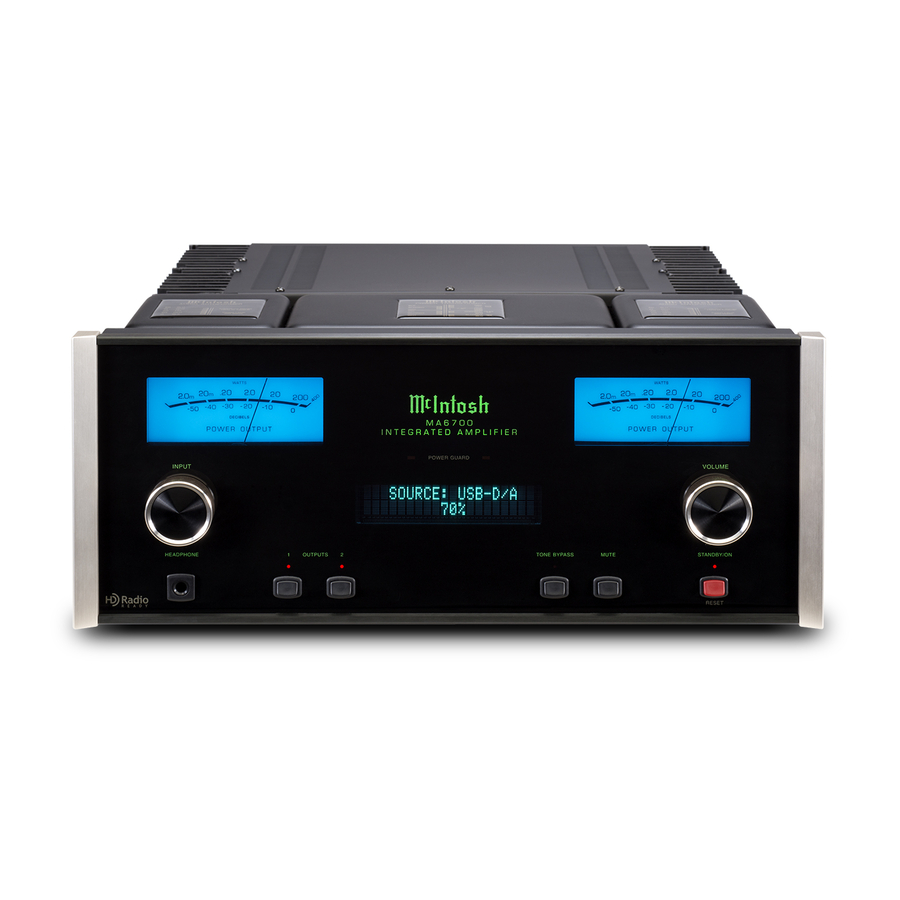
Page 20: Front Panel Displays, Controls, Push-Buttons And Jack
INPUT Control allows the selection LED indicates when the Left LED indicates when the Right VOLUME Control allows of various sources for listening and Channel Amplifier POWER Channel Amplifier POWER adjustment of the listening level recording. GUARD circuit activates GUARD circuit activates for both channels. -
Page 21: How To Operate The Setup Mode
Number for this unit; see page 22 for addition- MA6700 or MAC6700. Function Name Setting Page No. al information. Refer to figure 2A for the MA6700 3. These Setup Adjustments Appear only when the V_._ _ and Figure 2B for the MAC6700. MA6700 or MAC6700... -
Page 22: Firmware Version
“S/N” is the serial number of the unit SETUP: SOURCE INPUT sible with the Remote Control. (or higher). Refer to figure 2A for the MA6700 and 2. The Phono MC (Moving Coil) and MM (Mov- : RCA Figure 2B for the MAC6700. -
Page 23: Source Input Reassigment
CONTROL and the Front Panel Display will revert >> MUX Note: 1. These Setup adjustments appear only when back to its normal display. the McIntosh TM2 or TM3 Tuner Module is Figure 10 installed in the MA6700 or MAC6700. Source Input Renaming 4. -
Page 24: Source Input Renaming
Passthru The MA/MAC6700 can be part of a Multichannel Front Panel Alphanumeric Display. Refer to figure SETUP: TRIG1 OUTPUT Sound System for SACD, DVD-Audio and Home Action: REMOTE Theater. The Right and Left Front Channels from an SETUP: PASSTHRU Audio/Video Control Center or Surround Decoder Figure 18 Source: SRVR<RCA>... -
Page 25: Comm Port Baud Rate
Setup, con’t Comm Port Baud Rate 7. Press the VOLUME Control repeatedly until the 12. Rotate the INPUT CONTROL until the Setup The MA/MAC6700 may be remotely controlled from Source Input Menu item “SETUP: TRIG1 OUT- Menu item “SETUP: TRIG2 OUTPUT, Action: other equipment connected to the Rear Panel RS232C PUT, Source: TUNER FM OFF”... -
Page 26: Remote Control Codes
3. To exit from the Setup Mode, press the INPUT codes perform steps A and B then enter utilizes the NORMal McIntosh Control Codes. The CONTROL and the Front Panel Display will revert 3, 2, 4, 2 and 8 for step C. -
Page 27: Tm2 Tuner Module Firmware Version
Setup, con’t TM2 Tuner Module Firmware Version TM2 Tuner Module Clear Presets Your McIntosh MA/MAC6700 with the TM2 Tuner The TM2 AM/FM Tuner has three different Tuning 3. After the “Clear Presets” choice has been selected Module installed has been factory configured for Modes when installed into the MA/MAC6700. -
Page 28: Tm3 Tuner Module Firmware Version
TM3 Tuner Module Firmware Version TM3 Tuner Module Clear Presets Your McIntosh MA/MAC6700 with the TM2 Tuner The TM3 AM/FM Tuner has three different Tuning 3. After the “Clear Presets” choice has been selected Module installed has been factory configured for Modes when installed into the MA/MAC6700. -
Page 29: Tm3 Tuner Regions
Note: For additional information contact your receiving standards: McIntosh Dealer. Note: Changing the current Tuner Region will result in 3. To exit from the Setup Mode, press the INPUT clearing of all the Station Presets. -
Page 30: How To Operate The Ma/Mac6700
To switch ON the MA/MAC6700, Press the Figure 52 Available Trim Functions Source Selection STANDBY/ON Push-button on the Front Panel or MA6700 or MA6700 or Rotate the INPUT Control to select the desired source press the (Power) Push-button on the Remote... -
Page 31: Balance, Bass, Treble
How to Operate the MA/MAC6700 BALANCE BALANCE: 50 dB BASS: -12 dB Listening balance varies with ¦¦ ¦¦¦¦ ¦¦¦¦ ¦ ¦¦¦¦¦ ¦ ¦ different program sources, room acoustics and listening Figure 55 Figure 59 positions relative to the Loud- The Front Panel Display indicates the Bass changes BALANCE: 50 dB speakers. -
Page 32: Trim Level And Tone Control
How to Operate the MA/MAC6700, con’t The Front Panel Display indicates the Treble changes and press the VOLume Push-button +/- for the 5. Press the TRIM LEVEL +/-Push-button on the in steps from +12dB to -12dB. After approximately desired listening level. Remote Control to achive the same relative vol- 5 seconds the Display returns to indicate the Source 2. -
Page 33: Mono/Stereo Mode And Phono Adjustments
How to Operate the MA/MAC6700, con’t PHONO ADJUSTMENTS TONE CONTROL DISPLAY When the Phono MC Input is selected, an additional : ENABLE Brightness: TRIM SELECT FUNCTION becomes available for adjustment. Perform the following steps to make the Figure 65 Figure 70 3. -
Page 34: Display Brightness And Digital Audio Display 33 Meter Backlight And Tuner Control
“Tuner Text” are only available when a Figure 73 AM and FM broadcasts (the default McIntosh TM2 or TM3 Tuner Module is installed setting). in the MA6700 or MAC6700. 2. Press TRIM LEVEL + / - Push-button to switch B. -
Page 35: Tuner Text And Tuner Blend Mode
Mode” is only available when a McIntosh TM2 Figure 82 with the word MUTE in place of the actual volume Tuner Module is installed in the MA6700 or After approximately 5 seconds the Display returns to setting. Refer to figure 83 on the next page. -
Page 36: Headphone Jack And Power Output Meters
PUT Jacks. Refer Figure 85 to figure 85. Note: The McIntosh Jumpers must be connected, be- tween the above mentioned jacks, when the MA/ MAC6700 Internal Power Amplifier is to be used. The second way is to use both a separate power amplifier and the MA/MAC6700 built-in Power Amplifier. -
Page 37: Using Output 2 And Passthru
USB Audio Windows Driver Installation and Operation Guide MAC6700 will resume normal operation. and under “Model Num- McIntosh Laboratory, Inc. 2 Chambers Street Binghamton, New York 13903-2699 Phone: 607-723-3512 www.mcintoshlabs.com Note: This can be performed with the MA/MAC6700 ber” select MA/MAC6700, PASSTHRU On or in the Standby Mode. -
Page 38: Resetting The Ma/Mac6700 To Default Settings
How to Operate the MA/MAC6700, con’t Resetting the MA/MAC6700 to default settings If it becomes desirable to reset all the adjustable set- tings (Setup and Trim Settings) to the factory default values, perform the following: 1. Press in and hold the INPUT/TRIM Control and the VOLUMES/ADJUST Control. -
Page 39: Operating The Tm2 And Tm3 Tuner
If an external McIntosh Tuner Component is con- change. Figure TM3 nected to either the MA6700 or MAC6700 please refer to the Owner’s Manual supplied with the tuner com- AM or FM Band Selection 91.5 MHz ponent for Radio Station reception. -
Page 40: Creating Presets
Operating the TM2 and TM3 Tuner, con’t ing the VOLUME/TUNE Control to select the desired Clearing Presets using the Upp or Downq Directional Push-buttons. Preset Number. 6. Select the Station Preset to be removed. Refer to figure TM7 on page 39. Notes: 1. -
Page 41: Direct Access Tuning
103.3MHz using the Remote Control Numeric possible to display at the same time. This information 2. The McIntosh TM2 Tuner Module is used Push-buttons by pressing the number 1, 0, 3, 3. may include some or all of the following: in the U.S.A., Argentina, Bolivia, Brazil,... -
Page 42: Manual Hd Radio Program Selection
How to Operate the MA/MAC6700, con’t Operating the TM2 and TM3 Tuner, con’t the choice of listening to Multiple Programs. Lastly, Selecting HD Radio Program Preset 91.5 MHz ¦HD2¦¦ most HD Radio Stations send out Text Information 2. Select the HD Radio Program Preset by using the WWWW-FM which is displayed on the Front Panel of the MA/ Remote Control PRESET... -
Page 43: Specifications
MA/MAC6700 Amplifier Specifications Amplifier Specifications Power Output Preamplifier Output 1 and 2 (for rated input) Wide Band Damping Factor 200 watts is the minimum sine wave continuous aver- 1.4V unbalanced (8V Maximun) Greater than 40 age power output per channel, both channels operating Sensitivity (for rated output) Input Impedance Output Load Impedance... - Page 44 Amplifier Specifications, con’t TM2 - FM HD Radio Specifications TM2 - FM Analog Specifications, con’t Stereo: 0.4% Power Guard Sensitivity Less than 2% THD with up to 16dB overdrive at -85dBm Channel Selectivity 1,000Hz 65dB Adjacent Channel Signal To Noise Ratio 74dB Alternate Channel Voltage Gain 85dB...
- Page 45 75 Ohms, Type “F” Coax connector 350uV/m AM Antenna Input Balanced, RJ45 connector Useable Sensitivity Signal To Noise Ratio (for use only with supplied McIntosh RAA2 Remote 50dB 2.2uV (18.1dBf) AM Antenna) 50dB Quieting Sensitivity Frequency Response RAA2 Connection Cable 1.5uV (14.8dBf)
-
Page 46: Specifications
Height is 5 inches (12.7cm) Height is 7-5/8 inches (19.37cm) including feet Depth is 22 inches (55.88cm) including the Front Panel, Knobs and Cables Weight (MA6700) 74 pounds (33.6 kg) net, 92 pounds (41.7 kg) in ship- ping carton Weight (MAC6700) 75 pounds (34.1 kg) net, 93 pounds (42.3 kg) in ship-... -
Page 47: Packing Instructions
#10 flat washer 1-3/4 inch needed, please call or write Customer Service Depart- 017937 Plastic foot ment of McIntosh Laboratory. Refer to page 3. Please 400159 #10-32 x 3/4 machine screw see the Part List for the correct part numbers. - Page 48 McIntosh Laboratory, Inc. 2 Chambers Street Binghamton, NY 13903 www.mcintoshlabs.com The continuous improvement of its products is the policy of McIntosh Laboratory Incorporated who reserve the right to improve design without notice. Printed in the U.S.A. McIntosh Part No. 04137200...
Need help?
Do you have a question about the MA6700 and is the answer not in the manual?
Questions and answers