Marantz SR9300 User Manual
Av surround receiver
Hide thumbs
Also See for SR9300:
- Specification (16 pages) ,
- Specifications (4 pages) ,
- Service manual (2 pages)
Table of Contents
Advertisement
Advertisement
Table of Contents

Related Manuals for Marantz SR9300


Summary of Contents for Marantz SR9300
- Page 1 Model SR9300 User Guide AV Surround Receiver...
- Page 2 Kvitto eller faktura är tillräokligt bevis fö detta. NEDERLANDS DANSK GARANTIE Voor inlichtingen omtrent garantie dient u zich tot uw plaatselijke Marantz. GARANTI UW KWITANTIE, KASSABON E.D. BEWAREN Henvend dem til Deres MARANTZ-forhandler angående inrformation om garantien.
- Page 3 The SR9300 is in conformity with the EMC directive and low-voltage directive. Français Le SR9300 est conforme à la directive EMC et à la directive sur les basses tensions. Deutsch Das Modell SR9300 entspricht den EMC-Richtlinien und den Richtlinien für Niederspannungsgeräte.
-
Page 4: Table Of Contents
AUX2 INPUT ..................46 OPERATING AMP & TUNER ............... 14 BASIC OPERATION (TUNER) ....47 SHOW THE STATUS OF SR9300 ON THE LCD OF RC3200A ..16 WORKING WITH MODES ..............17 LISTENING TO THE TUNER ............... 47 ADJUSTING THE SETTINGS .............. 17 PRESET MEMORY ................ -
Page 5: Foreword
• Insert the plugs securely. Incomplete connection may result in noise. COPYRIGHT • Prior to connecting other audio and video equipment to the SR9300, Recording and playback of any material may require consent. For please read their owner’s manuals. further information refer to the following:... -
Page 6: Features
FEATURES FLEXBILITY FEATURES FUTURE-PROOF INTERFACE ARCHITECTURE a versatile RS232 port allows the SR9300’s internal Flash Memory to AMPLIFIER FEATURES be directly computer accessed for installing such future upgrades as new DSP algorithms, new surround formats/parameters, and other • THX Ultra certified types of processing updates. -
Page 7: Description
Dolby Laboratories and the THX division of Lucasfilm Ltd. correcting the tonal and spatial errors that occur. When the THX mode of the SR9300 is on, three distinct THX In a movie theater, film soundtracks that have been encoded with... - Page 8 • Neo 6 technology allows various sound elements within a channel Dolby Digital EX creates six full-bandwidth output channels from 5.1- or channels to be steered separately, and in a way which follows channel sources. This is done using a matrix decoder that derives naturally from the original presentation.
-
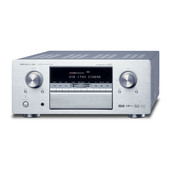
Page 9: Front Panel
FRONT PANEL AV SURROUND RECEIVER SR9300 SELECTOR VOLUME DOWN DISPLAY CLEAR MEMO DOWN GYRO TUNING AUTO-TUNE T-MODE SELECT ENTER MUTE VCR 1 VCR2/DVD-R TAPE CD-R TUNER MULTI-SPK SLEEP S-DIRECT AUX1 STANDBY AUX1 INPUT DIGITAL S-VIDEO VIDEO AUDIO MULTI ROOM 7.1CH-IN... -
Page 10: Mute Button
@5 PHONES jack for stereo headphones Press this button to mute the output to the speakers. Press it again to This jack may be used to listen to the SR9300’s output through a pair return to the previous volume level. -
Page 11: Fl Display
¡6 a DISP (Display Off) indicator k ENCODED CHANNEL STATUS This indicator lights when the SR9300 is in the display off condition. indicators These indicators display the channels that are encoded with a digital s PRO LOGIC II mode indicators (MOVIE, input signal. - Page 12 This indicator lights when the seep timer function in main-room is in use. ¡7 NIGHT mode indicator This indicator lights when the SR9300 is in the Night mode, which reduces the dynamic range of digital program material at low volume levels.
-
Page 13: Rear Panel
SCART IN connector on theSR9300 and connect When the jumper plugs that link the Preamp Outputs with these inputs TV’s SCART terminal to MONITOR OUT(SCART) on the SR9300. are removed, these jacks may be used to connect an external source By sending the pure DVD SCART video signal directly, the DVD signal to the internal amplifiers. - Page 14 UNSWITCHED outlet is provided. This is always live as long as the SR9300 is plugged into a live outlet. Then install the remote transmitter in an unblocked location where you can easily receive IR signal.
-
Page 15: Remote Control Unit Rc3200A
C S (Status) button Insert the new batteries (AA type) with correct (+) and (–) polarity. Press this button to see (jump to) the status of SR9300 on LCD panel. D M (Menu) button Use this button to entry the OSD menu system. -
Page 16: Activating The Rc3200A
REMOTE-CONTROLLABLE RANGE The distance between the transmitter of the remote control unit and the IR SENSOR of the SR9300 should be less than about 5 meters. If the transmitter is pointed to a direction other than the IR SENSOR or if there is an obstacle between them, remote control may not be possible. -
Page 17: Operating Amp & Tuner
INPUT SELECT 2 OPERATING AMP & TUNER AMP PAGE 3/8 To control the SR9300 by your RC3200A, you have to select the device AMP or TUNER on HOME screen. MAIN AMP PAGE 1/8 Tape, LD, AUX1, AUX2, VCR2, CD-R These buttons are used for selecting an input source. (see page 38) -
Page 18: Surround Mode
SURROUND MODE 3 AMP PAGE 7/8 Power On and Off buttons These buttons are used to turn on or off SR9300 AM, LW, FM buttons These buttons are used to switch between FM, AM, and LW mode of the tuner. -
Page 19: Show The Status Of Sr9300 On The Lcd Of Rc3200A
TUNER PAGE 2/3 SHOW THE STATUS OF SR9300 ON THE LCD OF RC3200A RC3200 has 2way communication with SR9300, it shows some status screen for SR9300. 1/2 Status To show 1 page of status screen, press S button . Frequency Direct button This button is used to select the mode of frequency direct input. -
Page 20: Working With Modes
WORKING WITH MODES ADJUSTING THE SETTINGS RC3200A starts up in Use mode. In this mode you operate your The RC3200A settings can be adjusted in the Setup mode. devices. For customizing the RC3200A (adjusting the settings, Press and hold the Mode button for 3 seconds. learning buttons or recording macros) you have to switch to the The Mode screen appears. - Page 21 SECOND SETUP PAGE Tap the Revert button. A message screen appears to confirm or cancel the revert On the second setup page you can adjust: process. • the date; • the time. Press OK or Cancel. TO EXIT SETUP MODE Adjust the Date Press the Mode button.
-
Page 22: Learning Commands
Press and hold the button on the existing remote control you want LEARNING COMMANDS to learn to the RC3200A. If an IR code or a brand is not in the database, you can program When the RC3200A receives an IR code: RC3200A commands by transmitting IR signals from your existing •... - Page 23 Tap Macro button. Tap Start. Macro screen appears. The HOME screen appears with the 'Recording' label at the top of the screen. The buttons you tap on this screen will not be recorded. From the HOME you can go to the different devices or you can press the Extra hard button to go to the Extra screen with delays and beeps.
-
Page 24: Rc3200A Edit
RC3200edit is the tool for you to use. You can find more information and updates of the software on http:// www.marantz.com. RC3200edit is the visual editor for creating and configuring RC3200A Configuration Files (NCF) on your computer. An NCF is a file that is used to define the RC3200A behaviour and look for the LCD touch screen. -
Page 25: Important Notices
IMPORTANT NOTICES Take care not to scratch the touch screen Use your finger to tap the LCD touch screen or use plastic-tipped pens intended for use with touch screens. Never use an actual pen, pencil or other sharp object on the LCD touch screen. -
Page 26: Connections
CONNECTIONS HEIGHT OF THE SPEAKER UNITS Front left and right speakers, and a center speaker Align the tweeters and mid-range drivers on the three front speakers on the same height as well as possible. SPEAKER PLACEMENT Surround left and right speakers, and surround back speaker The ideal surround speaker system for this unit is 7-speaker systems, Place the surround left, right and surround back speakers higher to using front left and right speakers, a center speaker, surround left and... -
Page 27: Connecting Speakers
MULTI PRE OUT MAIN IN ROOM LEFT LEFT MULTI VIDEO MONI. ANTENNA FRONT MULTI ROOM RIGHT RIGHT COAX MONITOR MODEL NO.SR9300 SURR. CENTER BACK LEFT RS232C SURR. SURR. BACK LEFT FRONT RIGHT EXT. IR SURR. SURR. DC OUT 1 DC OUT 2... -
Page 28: Connecting The Audio Components
FRONT MULTI PRE OUT MAIN IN ROOM LEFT LEFT MULTI VIDEO MONI. ANTENNA FRONT MULTI ROOM RIGHT RIGHT COAX MONITOR MODEL NO.SR9300 SURR. CENTER BACK DIGITAL LEFT INPUT RS232C SURR. SURR. BACK LEFT FRONT RIGHT EXT. IR SURR. SURR. DC OUT 1... -
Page 29: Connecting Video Components
MULTI PRE OUT MAIN IN ROOM LEFT LEFT MULTI VIDEO MONI. ANTENNA FRONT MULTI ROOM RIGHT RIGHT COAX MONITOR MODEL NO.SR9300 SURR. CENTER BACK LEFT RS232C SURR. SURR. BACK LEFT FRONT RIGHT EXT. IR SURR. SURR. DC OUT 1 DC OUT 2... - Page 30 FRONT MULTI PRE OUT MAIN IN ROOM LEFT LEFT MULTI VIDEO MONI. ANTENNA FRONT MULTI ROOM RIGHT RIGHT COAX MONITOR MODEL NO.SR9300 SURR. CENTER BACK LEFT RS232C SURR. SURR. BACK LEFT FRONT RIGHT EXT. IR SURR. SURR. VIDEO AUDIO DC OUT 1...
-
Page 31: Advanced Connecting
ROOM PRE OUT MAIN IN LEFT LEFT MULTI VIDEO MONI. ANTENNA FRONT MULTI ROOM RIGHT RIGHT COAX MONITOR DIGITAL MODEL NO.SR9300 OUTPUT SURR. CENTER BACK LEFT RS232C SURR. SURR. BACK LEFT FRONT RIGHT EXT. IR SURR. SURR. DC OUT 1... -
Page 32: Connecting The Antenna Terminals
MULTI PRE OUT MAIN IN ROOM LEFT LEFT MULTI VIDEO MONI. ANTENNA FRONT MULTI ROOM RIGHT RIGHT COAX MONITOR MODEL NO.SR9300 SURR. CENTER BACK LEFT RS232C SURR. SURR. BACK LEFT FRONT RIGHT EXT. IR SURR. SURR. DC OUT 1 DC OUT 2... -
Page 33: Connecting Remote Control Jacks
Therefore you need to aim the remote FRONT MULTI ROOM RIGHT RIGHT COAX MONITOR signal only to the unit. Also, if a Marantz power amplifier (some models MODEL NO.SR9300 SURR. CENTER BACK excluded) is connected with this terminal, the power amplifier’s power LEFT RS232C switch is synchronized with this unit’s power switch. -
Page 34: Setup
EXIT and press the OK button. component input of your TV or projector. (see 26 page) • In order to view the SR9300’s displays, the correct video source must be selected on the video display. -
Page 35: Input Setup (Assignable Digital Input)
“None.” • Required for enjoying THX Surround EX audio. After you have installed the SR9300, connected all the components, and determined the speaker layout, it is now time to Lucasfilm/THX recommends the use of two Surround Back speakers to enjoy the full potential of THX Surround EX.. -
Page 36: Thx Audio Setup
This is important for the timing of the acoustics to create the proper 2 - 2 T H X AUD I O S E T U P sound space that the SR9300 and today’s sound systems are able to produce. - Page 37 When you move cursor to FRONT L by pressing Down cursor bass begins to distort or you reach the maximum level with the VOL+, VOL– or Right / Left cursor button, the SR9300 will emit a pink noise from the front left button. speaker.
-
Page 38: Preference
Left or Right cursor button. The tonal balance of a film soundtrack will be If you select “ENABLE”, SR9300 will display the status excessively bright and harsh when played back of the feature (Volume up/down, input select, etc..) on over audio equipment in the home. -
Page 39: Plii (Pro Logic Ii) Music Parameter
This can be popped out of the surround audio effects ambience from stereo sources such as CDs. allowing the listener to easily discern what the actors In this mode, SR9300 includes three controls to fine-tune the say. soundfield as follow. -
Page 40: 7.1 Ch Input Level
• The condition of these setup will be memorized to 7.1CH INPUT source. DC TRIGGER SETUP SR9300 has two DC trigger control jacks, each one is selectable to link with input functions for the main room or multi room. Select “DC TRIGGER” in MAIN SETUP MENU with Up or Down cursor button, and press the OK button. -
Page 41: Basic Operation (Play Back)
(Maximum value of channel level)”.) • As the input is changed, the SR9300 will automatically switch to the digital input, surround mode, attenuation, and night mode status that were entered during the configuration process for that source. -
Page 42: Temporarily Turning Off The Sound
7.1CH-IN AUX2 POWER ON/STANDBY PHONES To program the SR9300 for automatic standby, press SLEEP buton or tap the Sleep on the remote. Each press of the button will increase the time before shut down in the following sequence. The sleep time will be shown for a few seconds in the display on the front panel, and it will count down until the time has elapsed. -
Page 43: Surround Mode
LFE channel. momentarily interrupt the output. The DTS mode cannot use when an analog input has been selected. When the signal in another digital format is input, output of SR9300 THX CINEMA will be muted. THX Cinema mode applies additional processing to Dolby Digital, DTS-ES (DISCRETE 6.1, MATRIX 6.1) - Page 44 * You may not be able to play some HDCD source signals from This mode is used to create a wider, deeper and more natural certain CD players if you connect the player to the SR9300 digitally. soundstage from two channel source material.
- Page 45 The relation between the selected surround mode and the input signal The surround mode is selected with the surround mode buttons on SR9300 or the remote control unit. However, the sound you hear is subject to the relationship between the selected surround mode and input signal. That relationship is as follows;...
- Page 46 Output Channel Front information display Surround Mode Input Signal SL SBL Signal format L/R C SubW Channel status Dot matrix display Segments SR SBR indicators 2 DIGITAL DOLBY Dolby D Surr. EX O O O O O L,C,R,SL,SR,S,LFE DOLBY D (PL2-movie) DTS-ES (dts , ES)
-
Page 47: Other Function
OTHER FUNCTION VIDEO ON/OFF When no video signals of a DVD, etc., are connected to the SR9300 or the DVD, etc., are connected directly to a TV, the unnecessary video TV AUTO ON/OFF FUNCTION circuit can be turned off by selecting the “VIDEO OFF” setting. -
Page 48: Recording An Analog Source
In normal operation, the audio or video source selected for listening When a digital audio recorder is connected to the DIGITAL outputs, through the SR9300 is sent to the record outputs. you are able to record the digital signal using a CD-R, MiniDisc or This means that any program you are watching or listening to may be other digital recording system. -
Page 49: 7.1 Ch Input
7.1 CH INPUT. The SR9300 is equipped for future expansion through the use of Multi channel SACD or DVD-Audio player. This is selected, the input signals connected to the FL(front left), FR(front right), CENTER, SL (surround left), SR (surround right), SBL (surround back left) and SBR (surround back right) channels of the 7.1... -
Page 50: Basic Operation (Tuner)
MULTI ROOM 7.1CH-IN AUX2 VOLUME DOWN DISPLAY CLEAR MEMO DOWN GYRO TUNING AUTO-TUNE T-MODE (USING THE SR9300) ENTER VCR 1 VCR2/DVD-R TAPE CD-R TUNER MUTE To select tuner and desired band (FM, LW or AM), press the MULTI-SPK SLEEP S-DIRECT... - Page 51 Preset stations are recalled in sequence (No.1 → No.2 → etc.) for 5 seconds each. (Using the SR9300) No stored preset number will be skipped. Tune into the radio station you desire (Refer to the “MANUAL You can fast forward the preset stations by tapping the Preset^ TUNING”...
-
Page 52: Rds Operation
Now in use in many countries, RDS (Radio Data System) is a description of the station's programming hidden space in the FM SELECTOR VOLUME signal. SR9300 is equipped with RDS to assist in the selection of FM stations DOWN DISPLAY CLEAR MEMO... - Page 53 PTY AUTO SEARCH Your receiver is equipped to automatically search for stations transmitting any of 29 different program types. To search for a PTY, follow these steps: DISPLAY CLEAR MEMO DOWN GYRO TUNING AUTO VCR 1 VCR2/DVD-R TAPE MULTI-SPK SLEEP S-DIRECT AUX1 AUX1 INP...
-
Page 54: Multi Room System
In multi room mode, the multi room remote control unit can be MULTI SPEAKER TERMINALS used in the multiroom to operate the following functions. The SR9300 allows you to connect another set of speakers and place General: them in a different room or separated area for listening to music. -
Page 55: Troubleshooting
Are you operating the unit properly following user’s guide ? Marantz distributor or the Marantz Service Center in your country. Are the power amplifiers and speaker working properly ? SYMPTOM... - Page 56 Should the operation or display seem to be abnormal, reset the unit with the following procedure. The SR9300 is turned on, press and hold the SELECT and AUX1 buttons simultaneously for 3 seconds or more. Remember that the procedure will reset the settings of the function selector, Surround mode, delay time, TUNER PRESET etc., to their...
-
Page 57: Technical Specifications
Frequency Response (Analog Input / Source Direct) ..........8 Hz - 100 kHz (± 3 dB) (Digital Input / 96 kHz PCM) ... 8 Hz - 45 kHz (± 3 dB) DIMENSION 440 mm AV SURROUND RECEIVER SR9300 SELECTOR VOLUME DOWN DISPLAY... - Page 58 You can find your nearest Marantz sales company or distributor from this address. JAPAN Marantz Japan, Inc. 35-1 Sagami Ohno 7-Chome, Sagamihara-shi, Kanagawa 228-8505, Japan U.S.A Marantz America, Inc. 1100 Maplewood Drive Itasca, IL 60143, U.S.A EUROPE Marantz Europe B.V.
Need help?
Do you have a question about the SR9300 and is the answer not in the manual?
Questions and answers