Table of Contents
Advertisement
Advertisement
Table of Contents
Troubleshooting

Related Manuals for Scag Power Equipment Magnum III


Summary of Contents for Scag Power Equipment Magnum III
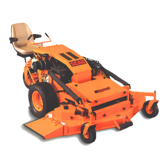
- Page 1 OPERATOR'S MANUAL PART 03027...
- Page 2 WARNING FAILURE TO FOLLOW SAFE OPERATING PRACTICES MAY RESULT IN SERIOUS INJURY. * Keep all shields in place, especially the grass discharge chute. * Before performing any maintenance or service, stop the machine and remove the spark plug wire and ignition key. * If a mechanism becomes clogged, stop the engine before cleaning.
-
Page 3: General Information
All information is based upon product information available maintenance and adjustment instructions in this manual. at time of approval for printing. Scag Power Equipment reserves the right to make changes at any time If additional information or service is needed, contact your without notice and without incurring any obligation. -
Page 4: Safety Information
Section 2 SAFETY INFORMATION 2.1 INTRODUCTION Your mower is only as safe as the operator. Carelessness or operator error may result in serious bodily injury or death. The signal word “DANGER” denotes that an extremely Hazard control and accident prevention are dependent upon hazardous situation exists on or near the machine that could result in high probability of death or irreparable injury if the awareness, concern, prudence, and proper training of... -
Page 5: Operation Considerations
Section 2 6. Prolonged exposure to loud noise can cause hearing 2.4 OPERATION CONSIDERATIONS impairment or loss. Operator hearing protection is 1. Know the function of all controls and how to stop recommended, particularly for continuous operation of quickly. the mower. Wear suitable hearing protection. 2. -
Page 6: Maintenance Considerations
Section 2 9. DO NOT turn sharply. Use care when backing up. 2.5 MAINTENANCE CONSIDERATIONS 1. Never make adjustments to the machine with the 10.Use counterweights or wheel weights when suggested engine running unless specifically instructed to do so. in this manual. If the engine is running, keep hands, feet, and clothing away from moving parts. -
Page 7: Safety And Instructional Decals
Section 2 2.6 SAFETY AND INSTRUCTIONAL DECALS DANGER SPINNING BLADE KEEP CLEAR CONTACT CAN INJURE 48071 WARNING ROTATING BLADES AND BELTS KEEP HANDS, FEET & CLOTHING CLEAR KEEP ALL GUARDS IN PLACE SHUT OFF ENGINE & DISENGAGE BLADE CLUTCH BEFORE SERVICING CLEAR AREA OF DEBRIS BEFORE MOWING USE CAUTION IN DIRECTING DISCHARGE KEEP BYSTANDERS, CHILDREN &... -
Page 8: Engine Specifications
Section 3 SPECIFICATIONS 3.1 ENGINE General Type ................Heavy Duty Industrial/Commercial Diesel Brand ..................Kubota 28 HP Super 5 Series, Electric Start Model ..................D1105-B Horsepower ................SAE Gross Intermittent, 28 HP @ 3000 RPM Type ................... Horizontal Shaft, Water Cooled, 4-Cycle Diesel Displacement ................ -
Page 9: Hydraulic System
Section 3 3.3 TRACTOR (CONT'D) Seat .................... Milsco Seat With Adjustment Lever For Forward and Back Movement Travel Speed: Forward ................0 - 8 MPH Infinitely Variable Reverse ................. 0 - 4.3 MPH Infinitely Variable 3.4 CUTTER DECK No. of Blades ................3 Width of Cut: Mag-61 ................. -
Page 10: Controls And Instrument Identification
Section 4 OPERATING INSTRUCTIONS Do not hold the key in the START position longer than CAUTION: 15 seconds. If the engine does not start, return the key to the OFF position for at least 60 seconds before a Do not attempt to drive this mower unless you restart attempt is made. - Page 11 Section 4 5. Temperature Gauge: Indicates engine coolant temperatures. Green zone indicates proper working Parking Brake Lever temperature. Red zone indicates engine over heating and the engine should be shut off immediately. 6. Fuel Gauge: Indicates the amount of fuel in the fuel tank.
-
Page 12: Safety Interlock System
Section 4 4.2 SAFETY INTERLOCK SYSTEM 4.3 INITIAL RUN-IN PROCEDURES (First Day of Use or Approximately 10 Hours) This mower is equipped with a safety system that prevents 1. Check all belts for proper tension at 2, 4 and 8 hours; the engine from starting unless the mower blade brake is adjust as needed. -
Page 13: Starting The Diesel Engine
Section 4 4.4 DIESEL ENGINE BREAK-IN 4. Turn the ignition key switch to the PREHEAT position until the indicator light for the glow plug glows bright red. The colder the temperature, the longer it will take The proper break-in of a new diesel engine can make a to energize the glow plug. - Page 14 Section 4 B. Seat Adjustment 1. To travel forward, depress the right foot pedal at the toe. (See Figure 4-6). The further the pedal is de- 1. Pull the handle on the left side of seat (Figure 4-5) and pressed the faster the mower will travel forward. move the seat either forward or back.
-
Page 15: Hillside Operation
Section 4 3. Always operate the engine at full throttle to 3. Check that all systems function correctly. properly maintain cutting speeds. If the engine 4. When traveling, the throttle control can be adjusted to starts to lug down, reduce the forward speed to increase or decrease travel speed. -
Page 16: After Operation
Section 4 -IMPORTANT- If at all possible, do not engage the mower brake with engine running at high speed, since premature wear of the electric clutch will oc- cur. Lower speed to near idle then engage the brake. CAUTION: The blade brake stops the blades from rotating. If the blades do not stop, contact your Scag Dealer. -
Page 17: Recommendations For Mowing
Section 4 4.13 RECOMMENDATIONS FOR MOWING -IMPORTANT- Do not wash a hot or running engine. Use compressed air to clean the engine and the 1. Keep the mower deck and discharge chute clean. radiator fins. Cold water will damage the engine and/or radiator. - Page 18 Section 4 4.15 TILTING THE MOWER DECK CAUTION: Do not tilt the deck with the mower blades rotating. Engage the blade brake before tilting the deck. Bodily injury or damage to the mower or property could result. 1. Stop the traveling movement of the mower and engage the blade brake.
-
Page 19: Troubleshooting Cutting Conditions
Section 5 TROUBLESHOOTING CUTTING CONDITIONS CAUSE CURE CONDITION Stringers - Occasional Low engine RPM Run engine at full 3600 RPM Blades of Uncut Grass Ground speed too fast Slow speed to adjust for conditions Wet grass Cut grass after it has dried out Dull blades, incorrect sharpening Sharpen blades Deck plugged, grass accumulation Clean underside of deck... -
Page 20: Troubleshooting
Section 5 TROUBLESHOOTING CAUSE CURE CONDITION Uneven Cut on Flat Lift worn off of blade Replace blade Ground - Wavy High-Low Blade upside down Mount with cutting edge toward Appearance, ground Scalloped Cut, or Rough Contour Deck plugged,grass accumulation Clean underside of deck Too much blade angle (deck pitch) Adjust pitch and level Deck mounted improperly See your authorized SCAG dealer... - Page 21 Section 5 TROUBLESHOOTING CAUSE CURE CONDITION Scalping - Blades Low tire pressures Check and adjust pressures Hitting Dirt or Cutting Very Close to Ground speed too fast Slow speed to adjust for conditions the Ground Cutting too low May need to reduce ground speed, raise cutting height, change direction of cut, and/or change pitch and level Rough terrain...
-
Page 22: Parking Brake Adjustment
Section 6 ADJUSTMENTS 6.2 FORWARD/REVERSE NEUTRAL 6.1 PARKING BRAKE ADJUSTMENT ADJUSTMENT The forward/reverse linkage should be adjusted whenever WARNING: the mower will not stay stationary when the forward/reverse (right) foot pedal is placed in the neutral position. Do not operate the mower if the parking brake is not operable. -
Page 23: Fan Belt Adjustment
Section 6 -NOTE- If you turn the nut too much, you will com- press the spring, making too much end play. Go to step 4. 4. If the drive wheels rotate in rearward travel direction, Locknut turn the adjustment bolt (Figure 6-1) clockwise until rotation stops. - Page 24 Section 6 3. After proper tension is obtained, tighten the two bolts Adjusting Bolt and install the pump belt guard. 6.6 PUMP DRIVE BELT ADJUSTMENT To adjust belt tension, turn the adjusting nut (Figure 6-1) until 1/2 inch deflection in belt is obtained with 10 pounds of pressure.
-
Page 25: Cutter Deck Adjustments
Section 6 6.10 BELT ALIGNMENT To level the deck, loosen the adjusting nut (Figure 6-8) and lift or lower the deck until the left side measurement equals the right side measurement. Tighten the adjusting nut. Belt alignment is important for proper performance of your Scag mower. - Page 26 Section 6 2. Turn the adjusting rods counter-clockwise to lower the front of the deck and clockwise to raise the front of the deck. When a difference of 1/4 inch from front to rear is obtained on left and right, tighten both jam nuts. Adjusting Nut Jam Nut Blade...
-
Page 27: Maintenance Chart - Recommended Service Intervals
Section 7 MAINTENANCE 7.1 MAINTENANCE CHART MAINTENANCE CHART - RECOMMENDED SERVICE INTERVALS HOURS Break-In 40 100 200 500 Procedure Comments (First 10) Check all hardware for tightness Check hydrostatic drive oil level See paragraph 7.3 Check engine belts for tightness See paragraph 7.9 Check cutter deck belts for See paragraph 7.10... - Page 28 Section 7 MAINTENANCE CHART - RECOMMENDED SERVICE INTERVALS (CONT'D) HOURS Break-In 40 100 200 500 Procedure Comments (First 10) Apply grease to fittings See paragraph 7.2 Change engine oil See paragraph 7.5 Clean air cleaner element See paragraph 7.7 Check engine belts for tightness See paragraph 7.9 Check cutter deck belts for See paragraph 7.10...
- Page 29 Section 7 7.2 LUBRICATION GREASE FITTING LUBRICATION CHART (SEE FIGURE 7-1) LUBRICATION LOCATION INTERVAL LUBRICANT OF PLACES 1. Cutter Drive Spindle 40 Hours/Weekly +Lithium MP White Grease 2125 2. Cutter Deck Spindles 40 Hours/Weekly +Lithium MP White Grease 2125 3. Caster Wheel Bearing 100 Hours/Bi-Monthly Chassis Grease 4.
- Page 30 Section 7 Figure 7.1 Grease Fitting Points...
-
Page 31: Hydrostatic Drive System
Section 7 7.3 HYDROSTATIC DRIVE SYSTEM B. Changing Hydraulic Oil A. Checking Hydraulic Oil Level The hydraulic oil should be changed after every 500 hours or annually, whichever occurs first. The oil should also be changed if the color of the fluid has become black or milky. The hydrostatic drive oil level should be checked after the A black color and/or a rancid oder usually indicates possible first 10 hours of operation. -
Page 32: Engine Oil
Section 7 3. Run the engine at idle speed with the hydrostatic drive (Figure 7-4) should be replaced after every 500 hours of system in neutral for five minutes. operation or annually, whichever occurs first. -IMPORTANT- 4. Check the oil level in the hydraulic tank. It must be 3 Replace the fuel filter cartridge and the pre- inches from the bottom of the fill opening. -
Page 33: Engine Coolant System
Section 7 1. Reach into the frame opening, indicated in Figure 7-4, and pull the fuel shut-off valve and pre-filter from their stored position in the frame. 2. Close the shut-off valve. Remove the two clamps securing the pre-filter to the fuel hose. Remove the pre-filter. - Page 34 Section 7 -IMPORTANT- Debris Screen Do not fill the radiator with coolant over the “FULL” level of the overflow bottle. When cool- ant is added, the coolant level drops the first time the engine is started. Stop the engine, and add more coolant. Figure 7-7 Debris Screen Removal -IMPORTANT- To prevent personal injury, always wear safety...
-
Page 35: Engine Air Cleaner
Section 7 1. Loosen the radiator cap, and open the radiator drain valve. Open the engine block drain valve located on CAUTION: the crankcase side of the engine. Drain the coolant element and remove the element (Figure 7-8). into a suitable container. Drain and clean the overflow bottle. - Page 36 Section 7 to instructions on the label attached to the element). INTERNAL — Drink large quantities of water. Follow with Milk Of Magnesia, beaten egg, or vegetable oil. Get medical attention 5. Replace the element after six cleanings or after every immediately.
- Page 37 Section 7 to recharge the battery using the engine alternator by first 2. The booster battery must be a 12 volt type. If a vehicle jump starting the mower and letting the engine run. See is used for jump starting, it must have a negative ground Jump Starting Instructions.
- Page 38 Section 7 Idler Pulley Fan Pulley Idler Pulley Clutch Belt Check Check Tension Tension Here Deflect 1/2" With Here 10 Pounds of Pressure Deflect 1/2" With 10 Pounds of Fan Belt Pressure Engine Pulley Engine Pulley Clutch Pulley Alternator Check Fan Pulley Pulley Tension...
-
Page 39: Cutter Blades
Section 7 7.11 CUTTER BLADES 5. If a blade cutting edge is dull or nicked, it should be sharpened. Remove the blades for sharpening. See “Blade Replacement”. A. Blade Inspection -NOTE- Check the mower blades for straightness, sharpness and Keep the blades sharp. Cutting with dull blades the condition of cutting edge every 8 hours of operation, or not only yields a poor mowing job, but slows daily (or more often when mowing abrasive type grass or... -
Page 40: Body, Deck And Upholstery
Section 7 3. Use mower deck lift switch to tilt the deck up as far as 7.13 BODY, DECK AND UPHOLSTERY it will go. 4. Holding the nut at the top of the blade drive pulley with a wrench, loosen and remove the blade attachment CAUTION: bolt from beneath the mower deck. - Page 41 ILLUSTRATED PARTS LIST MAGNUM III...
- Page 42 MAG-61, MAG-72 CUTTER DECK 390S0111...
-
Page 43: Cutter Deck
MAG-61, MAG-72 CUTTER DECK Ref. Part Mag Mag Ref. Part. Mag Mag No. Number Descripton No. Number Description 46867 Cutter Deck with Decals 04020-09 Nut, Hex, 5/8-11 46868 Cutter Deck with Decals 43278 Spacer, Cutter Blade 46631 Spindle Assembly 04001-01 Bolt, Hex Head, 1/4-20 x 3/4 Gr.5 43298 Shaft, Cutter Spindle... - Page 44 MAG-61, MAG-72 DECK SUPPORT 29 27 390S0112...
- Page 45 MAG-61, MAG-72 CUTTER DECK SUPPORT Ref. Part Mag Mag Ref. Part Mag Mag No. Number Description No. Number Description 45733 Cover, Belt 04029-03 Wingnut, Plastic, 3/8-16 48100-02 Bushing, Olite - 1-1/8 ID 04001-52 Bolt, Hex Head, 1/2-13 x 2-1/2 48100-08 Bushing, Olite - 1.00 ID 481195 Actuator, Deck Lift...
- Page 46 RIDER FRAME 390S0113...
- Page 47 RIDER FRAME Ref. Part Ref. Part No. Number Description No. Number Description 46029 Handle, Steering (Includes 2) 04021-08 Hex Locknut, Elastic Stop, 1/4-20 48159 Handle Grip 04017-17 Serr. Fl. Hex Head Capscrew, 5/16-18 x 1.00 04021-10 Hex Locknut, Elastic Stop, 5/16-18 04010-17 Screw, Flat Hed, #10-32 x 3/4 04040-15...
-
Page 48: Engine Deck
ENGINE DECK 38 10 390S0114... - Page 49 ENGINE DECK Ref. Part Ref. Part No. Number Description No. Number Description 04001-28 Bolt, Hex Head, 7/16-14 x 1-1/4 422002 Catch, Hood Latch 04003-12 Carriage Bolt, 5/16-18 x 3/4 04010-01 Screw, Round Head Washer, #10-32 x 1/2 43394 Stud, Metric 481309 Latch, Hood 48205...
-
Page 50: Radiator/Oil Cooler
RADIATOR/OIL COOLER 390S0115... - Page 51 RADIATOR/OILCOOLER Ref. Part No. Number Description 481207 Hose, Upper Radiator 48136-06 Clamp, Hose 45783 Shroud, Fan 04019-03 Serr. Fl. Hex Nut, 5/16-18 Tank, Coolant Overflow 422192 Mounting Bracket, Coolant Tank 04003-12 Carrage Bolt, 5/16-18 x .75 481286 Radiator with Oil Cooler 45784 Frame, Debris Screen 45785...
-
Page 52: Muffler And Air Cleaner
MUFFLER AND AIR CLEANER 390S0116... - Page 53 MUFFLER AND AIR CLEANER Ref. Part No. Number Description 48136-08 Hose Clamp 481191 Hose, Air Intake 481333 Cap. Precleaner 04100-03 U-Bolt 481192 Air Cleaner 421981 Mounting Bracket, Air Cleaner 04030-03 Lockwasher, 5/16 04020-03 Nut, Hex, 5/16-18 Gasket, Manifold 481340 Adapter, Manifold 04015-07 Capscrew, Socket Head, M8-1.125 x 20 422029...
- Page 54 DECK DRIVE SYSTEM 390S0117...
- Page 55 DECK DRIVE SYSTEM Ref. Part Ref. Part No. Number Description No. Number Description 04001-101 Bolt, Hex Head, 7/16-20 x 2-1/2 04021-09 Hex Locknut, Elastic Stop, 3/8-16 04030-05 Lockwasher, 7/16 04041-07 Flatwasher, 3/8 (.391 x .938 x .105) 481204 Clutch, Electric 48181 Pulley, Idler 481104...
- Page 56 PUMP AND FAN DRIVE SYSTEMS PART OF ENGINE 390S0118...
- Page 57 PUMP AND FAN DRIVE SYSTEMS Ref. Part Ref. Part No. Number Description No. Number Description 04021-16 Hex Locknut, 1/2-20 481114 Belt, Fan Drive 43335 Spacer, Fan 45713 Upright, Fan Support - RH 48442 Bearing 45307 Base, Idler Pivot - Pump 04003-19 Carriage Bolt, 1/2-13 x 1-1/4 44107...
-
Page 58: Instrument Panel
INSTRUMENT PANEL 12 11 390S0119... - Page 59 INSTRUMENT PANEL Ref. Page No. Number Description 48023 Hourmeter 481183 Gauge, Water Temperature 481306 Gauge, Fuel Level 481184 Voltmeter 46873 Instrument Panel with Decal 42413 Bracket, Fuse Holder 04021-01 Hex Locknut, Elastic Stop, #10-32 04010-11 Screw, Round Head, #10-32 x 1-1/2 04010-01 Screw, Round Head, #10-32 x 1/2 Timer, Glow Plug...
- Page 60 WIRING HARNESS AND ELECTRICAL COMPONENTS 390S0120...
- Page 61 WIRING HARNESS AND ELECTRICAL COMPONENTS Ref. Page No. Number Description 481216 Actuator, Cutting Height 481185 Wire Harness 481182 Indicator Light, Oil Pressure 48023 Hourmeter 481183 Gauge, Water Temperature 481306 Gauge, Fuel Level 481316 Timer, Delay Circuit 481322 Fuse, 30 Amp Timer, Glow Plug 481182 Indicator Light, Glow Plug...
- Page 62 CUTTER BRAKE LINKAGE 390S0121...
- Page 63 CUTTER BRAKE LINKAGE Ref. Part No. Number Description 04041-08 Flatwasher, 3/4 (.766 x 1.250 x .060) 04041-08S Flatwasher, 3/4 (.766 x 1.250 x .035) 04050-02 Retaining Ring - .75 Ext 45702 Lever, Clutch Engage 04021-10 Hex Locknut, Elastic Stop, 5/16-18 481163 Spring, Clutch Lever 04019-03...
-
Page 64: Parking Brake Linkage
PARKING BRAKE LINKAGE MAG008... - Page 65 PARKING BRAKE LINKAGE Ref. Part No. Number Description 48093 Grip, Handle 45716 Lever, Brake 48114-04 Grease Fitting 04050-01 Retaining Ring, .625 Ext 04020-05 Hex Locknut, Elastic Stop, 3/8-16 04041-07 Washer, Flat, 3/8 (.391 x .938 x .105) 48464 Ball Joint, 3/8-24 RH Thd 04021-09 Hex Locknut, Elastic Stop, 3/8-16 45782...
-
Page 66: Throttle Linkage
THROTTLE LINKAGE 390S0123... - Page 67 THROTTLE LINKAGE Ref. Part Number Description 04003-02 Carriage Bolt, 1/4-20 x .75 421776 Mounting Base, Throttle 04019-02 Serr. Fl. Hex Nut, 1/4-20 04001-13 Bolt, Hex Head, 5/16-18 x 2-3/4 46877 Lever, Throttle (Includes 6, 7) 48114-05 Grease Fitting 48100-04 Bushing, Oilite - .50 I.D. 44115 Rod, Throttle Control 04002-11...
- Page 68 FORWARD/REVERSE LINKAGE 390S0124...
- Page 69 FORWARD/REVERSE LINKAGE Ref. Part No. Number Description 04021-09 Hex Locknut, Elastic Stop, 3/8-16 48544 Ball Joint, 3/8-24 LH Thread 04041-07 Flatwasher, 3/8 (.391 x .938 x .105) 04003-05 Carriage Bolt, 3/8-16 x 1-1/2 04004-22 Rod, Transmission Control 45708 Bellcrank, Pump Control 04021-08 Hex Locknut, Elastic Stop, 1/4-20 04001-59...
-
Page 70: Fuel Tank And Lines
FUEL TANK AND LINES 390S0125... - Page 71 FUEL TANK AND LINES Ref. Part No. Number Description 46933 Fuel Tank (Includes 2, 3, 4) 481313 Fitting, Return Line 481304 Sender Unit, Fuel Level (Includes Gasket and Screws) 481312 Fitting, Hose 04017-16 Serr. Fl. Hex Head Capscrew, 5/16-18 x 3/4 481298 Cap, Diesel Fuel 45864...
-
Page 72: Hydraulic Circuits
HYDRAULIC CIRCUITS 390S0126... - Page 73 HYDRAULIC CIRCUITS Ref. Part No. Number Description 481292 Hose, Pump to Oil Cooler, 5/8 Hose Barb 48136-04 Clamp, Hose 481301-01 Elbow, 90°, 481202 Hose, Oil Cooler to Reservoir, 5/8 & 3/8 Hose Barb 48939 Elbow, 90° 48059-01 Clamp, Hose 48936-02 Coupling, Hose, 7/8-14 SAE x 5/8 Hose Barb 48350-13 Elbow, 90°, 1-1/16-12 JIC x 7/8-14 O-Ring...
-
Page 74: Control Panel
*DELAY MODULE TIMER CONTROL PANEL *VOLTMETER *FUEL GAUGE *WATER PINK TEMPERATURE GAUGE *HOURMETER FUSE *LOW OIL HOLDER PRESSURE LIGHT *GLOW PLUG PINK TIMER *GLOW PLUG LT. BLU LIGHT *CLUTCH KILL CIRCUIT PURP *SYNCHO-START ORN/WHT RELAY RELAY *DECK LIFT RED/WHT PINK YEL/BLK SWITCH PURP... -
Page 75: Heavy Duty
Ref. Part No. Number Description 48071 Decal, Danger - Spinning Blades 481040 Decal, Warning - Rotating Blades 481326 Decal, Magnum III 48072 Decal, Heavy Duty Commercial 481039 Decal, Warning - Belt Cover 48404 Decal, Metalcraft - Made In USA 481355 Decal, Scag Logo - 12"... -
Page 76: Limited Warranty-Commercial Equipment
Scag, are either incompatible with the Scag mower or adversely affect its operation, performance or durability. Scag Power Equipment reserves the right to change or improve the design of any mower without assuming any obligation to modify any mower previously manufactured. - Page 77 © 1996 PART NO. 03027 SCAG POWER EQUIPMENT, INC. PRINTED 1/96 DIVISION OF METALCRAFT OF MAYVILLE PRINTED IN USA...
Need help?
Do you have a question about the Magnum III and is the answer not in the manual?
Questions and answers