
Related Manuals for QSC Weatherized WideLine Series


Summary of Contents for QSC Weatherized WideLine Series
- Page 1 Weatherized WideLine Series User Manual WL2102-wx Loudspeaker WL3082-wx Loudspeaker GP218-wx Subwoofer TD-000307-00 Rev. A *TD-000307-00*...
-
Page 2: Important Safety Precautions And Explanation Of Symbols
QSC Audio Products 3-Year Limited Warranty QSC Audio Products, LLC (“QSC”) guarantees its products to be free from defective material and / or workmanship for a period of three (3) years from date of sale, and will replace defective parts and repair malfunctioning products under this warranty when the defect occurs under normal installation and use - provided the unit is returned to our factory or one of our authorized service stations via prepaid transportation with a copy of proof of purchase (i.e., sales receipt). -
Page 3: Package Contents
Package Contents WL2102-wx / WL3082-wx Loudspeakers Front Outer Rigging Link - WL3082-wx (10.5 in., 267 mm) (P/N CH-000980-00) Front Outer Rigging Link - WL2102-wx (8.6 in., 219 mm) (P/N CH-000987-00) Front Center Front Rigging Link (P/N CH-000981-00) M10 Flat Washer M10 Lock Washer Nylon Spacer M10 Hex Socket Cap Screw, 70L - WL3082-wx... - Page 4 WL2102-wx Loudspeaker a. Suspension Attachment Screws (Qty: 8) b. Suspension Links c. Grille d. Splay Angle Selector holes e. 25" Cable – Figure 3 – – Figure 4 – GP218-wx Loudspeaker a. Grille b. Non-Slip Feet c. 25" Cable – Figure 5 – –...
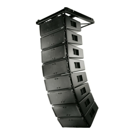
- Page 5 AF3082-wx and AF2102-wx Array Frames a. Shackle Holes (accept 5/8" (16 mm) screw pin anchor shack) b. Center Support Bar c. Suspension Plate d. Rigging Links e. Suspension Attachment Screws – Figure 7 – Suspending the Weatherized WideLines Rules for Suspension •...
- Page 6 Weatherized WideLine Working Load Limits and Design Factors (Table 1) lists the suspension components and provides Working Load Limit data at various Design Factors. The tabulated Design Factors are for static loads only. The choice of which Design Factor to use will depend upon the jurisdiction and venue of installation, as well as the conditions of suspension.
-
Page 7: Assembly Order
2. Install the hardware listed below onto both rear corners of the loudspeaker as shown in (Figure 9). Hand-tighten only at this time. Assembly Order a. Nylon Spacer b. Rear Suspension Link (removed earlier) c. M10 Flat Washer (removed earlier) d. - Page 8 Top or Middle Loudspeaker in the Array 1. Place the next loudspeaker assembly on a flat, stable surface, remove the two cap screws, flat washers, and lock washers from both top-rear corners as shown. Place aside for later use. 2. Loosen the two bottom-rear cap screws and rotate the rear-center rigging link 90° so that it is pointing down as shown. Hand-tighten the cap screws.
- Page 9 Note: Each hole on the Rear-center Rigging Link represents 1 degree of angle for setting the splay. The rows are numbered 0, 4, and 8, indicating holes 0 - 10. Use QSC's EASE Focus to determine the proper angles. You can download EASE Focus at (http://www.qscaudio.com/products/software/EASE_Focus/ease_focus.htm).
- Page 10 Assembling the Array Frame 1. Place the Array Frame on top of the top loudspeaker, aligning the rigging links with their respective rigging links on the top loudspeaker as shown below. 2. Secure the Array Frame to the top loudspeaker with two 70L / 50L cap screws in the rear, and two 70L / 50L cap screws in the front. Torque all cap screws to 60 in.-lbs.
-
Page 11: Specifications
Specifications WL3082-wx WL2102-wx GP218-wx Configuration Tri-amp only line-array Tri-amp only line-array Subwoofer Transducers HF: 1.4" exit, 3" diaphragm, neodymium HF: 1.4" exit, 3" titanium diaphragm, HF: N/A magnet compression driver neodymium magnet assembly LF: Dual 18" vented subwoofer LF: Dual, 8" woofer, 2.5" voice coil LF: Dual, 10"... - Page 12 Dimensions WL3082-wx Loudspeaker 20" 508 mm 9.5" 241.3 mm 15.5" 397 mm...
- Page 13 WL2102-wx Loudspeaker 27.25" 692 mm 11.75" 298.5 mm 18.5" 469.9 mm...
- Page 14 GP218-wx Subwoofer 47.32" 1201.8 mm 22.0" 560 mm 30" 765 mm...
- Page 15 AF3082-wx Array Frame 8.0" 203 mm 21.1" 536 mm 3.8" 95 mm 7.06" 179.4 mm 18.1" 459 mm...
-
Page 16: Mailing Address
© 2010 QSC Audio Products, LLC. All rights reserved. QSC and the QSC logo are registered trademarks of QSC Audio Products, LLC in the U.S. Patent and Trademark office and other countries. Speakon is a trademark of Neutrik. All other trademarks are the property of their respective owners. Patents may apply or be pending.
Need help?
Do you have a question about the Weatherized WideLine Series and is the answer not in the manual?
Questions and answers