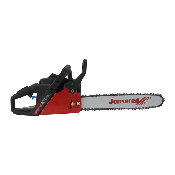
Jonsered 2036 Workshop Manual
Hide thumbs Also See for 2036:

Advertisement

Workshop Manual
Chain Saws
Contents
General recommendations
1. Safety equipment
2. Starter unit
3. Electrical system
4. Fuel system
5. Centrifugal clutch
6. Lubrication system
7. Cylinder and piston
8. Crankshaft and crankcase
9. Tools
10. Technical data
This manual covers models:
2041/2045/2050
2036/2040
2054/2055
625/630/670
2077/2083
2095
2
3
17
23
35
55
65
77
93
115
127
1

Advertisement

Table of Contents
loading

Summary of Contents for Jonsered 2036

  • Page 1 1. Safety equipment 2. Starter unit 3. Electrical system 4. Fuel system 5. Centrifugal clutch 6. Lubrication system 7. Cylinder and piston 8. Crankshaft and crankcase 9. Tools 10. Technical data This manual covers models: 2036/2040 2041/2045/2050 2054/2055 625/630/670 2077/2083 2095...
  • Page 2: Special Tools

    General recommendations Keep this in mind: Special tools – Do not start the engine without the clutch and clutch drum fitted. Some work operations in this workshop manual require the use of special tools. In each section where this is appropriate the tool –...
  • Page 3: Safety Equipment

    Safety equipment Contents Dismantling Disassembly Fitting Dismantling, mod. 2054/2055 Fitting, mod. 2054/2055 Dismantling, mod. 2077/2083 Fitting, mod. 2077/2083 Checking of automatic function Checking of brake action Chain catcher Throttle lock...
  • Page 4: Safety Equipment

    Safety equipment In addition to the chain brake the chain catcher and WARNING! right-hand guard on the rear handle are also con- Protective goggles must be sidered part of the chain saw’s safety equipment. worn during all work on the It is obviously important that the chain brake chain brake to prevent perso- functions as intended, but it is also important that...
  • Page 5 Safety equipment Remove the screws and the cover over Remove the screws and lift off the cover over the brake spring. the brake spring. WARNING! The brake spring is tensioned and can slip out of its position. Bend up the brake spring. Use a screwdriver and carefully bend up the spring.
  • Page 6 Safety equipment The brake band must have a minimum Check the wear on the brake band. thickness of 0.8 mm at the most worn At the most worn point the band must point. have a thickness of at least 0.8 mm. Otherwise it should be replaced with a new band.
  • Page 7: Starter Unit

    Safety equipment Fit the brake mechanism in the clutch Place the brake mechanism in position cover. on the clutch cover. Lubricate the bearing points with thin oil. Press in the toggle-joint’s bearing pin (A) and place the tubular pin (B) in position. Lubricate the bearing points with thin oil.
  • Page 8 Safety equipment Dismantle the protective plate over the Remove the protective plate over the guide bar attachment and the chain brake. guide bar attachment. Release the chain brake! Remove the screws and lift off the chain brake. Release the chain brake! WARNING! The brake spring is tensioned with a very large force and can cause per-...
  • Page 9 Safety equipment Dismantle the brake mechanism and Dissassemble the brake mechanism and replace worn or damaged parts. replace worn or damaged parts. The brake band should have a minimum thickness of 0.8 mm at the most worn place. 0,8 mm Assembly Mod.
  • Page 10 Safety equipment Dismantling Dismantling Mod. 2077/2083 Mod. 2077/2083 Dismantle the chain brake’s bearing on Remove the screw, sleeve and washer the starter unit side. for the chain brake’s bearing on the star- ter unit side. Remove the clutch cover, guide bar and chain.
  • Page 11 Safety equipment Replace the hand guard’s bearing pin if it The hand guard’s bearing pin can now is worn. easily be replaced. Press out the sprung tubular pin and pull Press out the spring tensioned tubular out the plate insert from the hand guard. pin and pull out the complete plate insert from the hand guard.
  • Page 12 Safety equipment Fit the brake band (A) and place the Press down the brake band in its rear toggle-joint in position over its bearing attachment (A). pin (B). Place the toggle-joint in position over its bearing pin (B). Make sure that it is correctly positioned. Press together the brake spring far Press the brake spring over the guide pin.
  • Page 13: Chain Catcher

    Safety equipment Checking of the brake Checking of the brake effect effect Start the engine. Place the saw on a stable surface and start the engine. Hold the handle with both hands and rev Hold the handle with both hands and rev Release the chain brake by turning the left wrist towards the hand guard without Release the chain brake by turning the...
  • Page 14 Safety equipment Fitting mod. 2036/2040 Fitting, mod. 2036/2040 Replace any damaged parts and fit in the Fit in the reverse order to dismantling. reverse order to dismantling. Note the following: ● Make sure that the spring comes on the correct side of the barrier in the throttle control.
  • Page 15: Electrical System

    Safety equipment Dismantling mod. 625/630/670 Dismantling mod. 625/630/670 Press out the fitted pin and dismantle the Press out the fitted pin approx. 13-14 mm so that the throttle control lock comes cover. loose. Dismantle the covers by means of pres- sing a screwdriver into the back edge of the covers.
  • Page 16 Safety equipment Fitting mod. 2095 Fitting mod. 2095 Replace damaged or worn parts and fit in Replace damaged or worn parts. the reverse order to dismantling. Fit in the reverse order to dismantling. Pay attention to the following: ● The spring’s straight shank should be fitted in the throttle control lock (1).
  • Page 17: Starter Unit

    Starter unit Contents Dismantling Replacement of return spring Replacement of starter cord Assembly Replacement of starter pawls...
  • Page 18 Starter unit WARNING! When working on the starter unit wear protective glasses to avoid eye injuries in the event that the return spring flies out. Dismantling Dismantling 1. Dismantle the starter from the engine 1. Remove all screws and lift off the unit.
  • Page 19 Starter unit 4. Remove the screw and the washer. 4. Remove the screw and washer in the centre of the pulley. 5. Remove the pulley and spring cass- 5. Lift off the pulley carefully. ette, and return spring. 6A.Remove the screws which hold the spring cassette and lift off.
  • Page 20 Starter unit B. Press down a new spring in the starter B. Return spring without cassette. housing. Leave the lock shackle round the spring in position. 1. Place the spring over its seat in the starter housing. 2. Press down the spring in the correct position by means of the thumbs and let the lock shackle slide over the spring.
  • Page 21 Starter unit Assembly Assembly 1. Wind the cord approx. 4 turns clock- 1. Wind the cord approx. 4 turns clock- wise round the pulley. wise round the pulley. 2. Fit the pulley. 2. Lubricate the pulley’s bearing pin and the return spring with a few drops of motor oil or non-freezing lubricant and fit the pulley.
  • Page 22 Starter unit 5. Assemble the starter in the reverse 6. Assemble the starter. order to dismantling. Pull out the starter cord a little. Put the starter in position. Release the starter cord and check that the pawls grip the pulley. Tighten the screws.
  • Page 23: Table Of Contents

    Electrical system Contents Checking ignition spark Replacing spark plug protection Dismantling Starter pawls Assembly Electrically heated handles Replacing the generator...
  • Page 24: Checking Ignition Spark

    Electrical system The chain saw is fitted with an electronic system NOTE! consisting of flywheel, ignition coil, and trigger When testing the chain saw’s heating system the unit. Certain saw models are fitted with a gene- guide bar, chain and clutch cover must be fitted rator system to heat the handles and carburettor.
  • Page 25 Electrical system Try with a new plug Try with a new plug. If there is no spark disconnect the short If there is still no spark remove the short circuiting cable from either the ignition circuiting contact. module or short circuiting contact. Replace the contact if necessary.
  • Page 26: Replacing Spark Plug Protection

    Electrical system Check other cables and connections. Still no spark? Check the other cables and connections for poor contact (dirt, corrosion, cable break and damaged insulation). Tips! Use an Ohm-meter to check if there is a cable break, e.g. as a result of pinching. Check the air gap.
  • Page 27: Dismantling

    Electrical system 3. Fit the contact spiral on the ignition 3. Fit the contact spiral on the ignition cable. cable and make sure that the wire is folded along the cable. 4. Pull the contact spiral into the spark plug protection. NOTE! It is important that the point of the contact spiral meets the middle of the ignition...
  • Page 28 Hold the chain saw in the air with the handle on the withdrawing tool. Mod. 2036/2040 Mod. 2036/2040 Thread the nut on the shaft to protect the Dismantle the flywheel by using a threads.
  • Page 29: Starter Pawls

    Replace damaged parts. For starter pawls which are mounted on a separate bridge the entire unit must be replaced. Mod. 2036/2040 Mod. 2036/2040 Press out the journals by means of a Replace the starter pawls and springs in suitable mandrel.
  • Page 30: Assembly

    Electrical system When fitting the starter pawls check the following: ● Washer between flywheel and starter pawls. ● The spring is not clenched. ● The starter pawls move freely. ● Use Locktite on the screw. Assembly Assembly Check that the keyway and key in the Check that the keyway and key in the crankshaft are undamaged.
  • Page 31: Electrically Heated Handles

    Electrical system Electrically heated Electrically heated handles handles Certain of our chain saws are fitted with The requisite output is generated by a electric heating of both the the front and generator placed behind the flywheel. rear handles. The electrical system is maintenance free and is controlled by means of a switch on the left-hand side of the chain saw.
  • Page 32 Electrical system Clean and measure both handle inserts between points 2 and 3. The switch should be in the switched off position. Correct measurement value: 1.4 - 1.8 Ohm. If the values measured differ from the recommended values measure each insert separately.
  • Page 33: Replacing The Generator

    Electrical system Replacing the generator Replacing the generator The generator must be replaced if the Replace the generator if it does not prov- voltage proves to be insufficient when ide sufficient voltage. checked. The generator is placed behind the flywheel. Remove the screws and lift off the gene- rator.
  • Page 35: Fuel System

    Fuel system Contents Air filter Centrifugal cleaning (Turbo) Fuel filter Carburettor Carburettor design Carburettor setting Fuel tank vent Trouble shooting schedule...
  • Page 36: Air Filter

    Fuel system In addition to the fuel tank and carburettor, the There are different makes of carburettors on our fuel system also includes the air filter, fuel filter different models, but the function and repair and tank vent. techniques are basically the same. All these components interact to ensure that the engine will have the optimum mixture of fuel and air to make it as efficient as possible.
  • Page 37: Centrifugal Cleaning (Turbo)

    Fuel system Centrifugal cleaning (Turbo) By means of utilising the centrifugal power during the cleaning of the induction air to the carburettor the air filter is guarantied much longer cleaning intervals. By means of the centrifugal power the larger impurities are sorted out since they are thrown out to the periphery of the air shell and out past the cylinder.
  • Page 38: Carburettor

    ● Close the choke valve to prevent dirt entering the engine. ● Blow clean the carburettor chamber with compressed air. Dismantling mod. 2036/2040 Dismantling mod. 2036/2040 Dismantle the carburettor. Dismantle the air filter and air filter holder, fuel pipe, throttle wire and choke lever.
  • Page 39 Fuel system Tips! Place the gasket on the carburettor and tighten the screws. Place the carburettor gasket, preferably with gasket paste, on the carburettor. Connect the screwdriver guide. Position the screws through the holes Fit the air filter. approx. 5 mm to centre the gasket. Tighten the screws.
  • Page 40 Fuel system Fix the carburettor gasket on the car- Fit the carburettor gasket on the car- burettor. burettor with gasket paste. Make sure that it is turned the right way round so that Place the filter holder against the car- the impulse channel is not blocked.
  • Page 41: Lift Up Carburettor And Dismantle

    Fuel system Lift up the carburettor and dismantle: Lift up the carburettor and dismantle: 1. The screwdriver guide for the carbu- 1. The screwdriver guide for the carbu- rettor’s adjusting screws. rettor’s adjusting screws. 2. The ventilation pipe from the nipple 2.
  • Page 42 Fuel system Unscrew the carburettor screws and lift Unscrew the carburettor screws and lift up the carburettor. up the carburettor. NOTE! The screw (A) which holds the vibration damper should not be dismantled. Fitting mod. 625/630/670 Fitting mod. 625/630/670 Fit the carburettor in the reverse order to Fit the carburettor in the reverse order to dismantling.
  • Page 43 Fuel system Lift up the carburettor and remove the air Lift up the carburettor and remove the air filter holder, throttle push rod and fuel filter holder, throttle push rod, and fuel pipe. pipe. Fitting mod. 2077/2083 Fitting mod. 2077/2083 Fit the carburettor in the following order: Fit the carburettor in the reverse order to dismantling.
  • Page 44: Carburettor Design

    Fuel system Lift up the carburettor and release the Lift up the carburettor and give full throttle throttle wire. by turning the throttle shaft. Lift up the throttle wire from the guide and release the tank vent pipe. Fitting mod. 2095 Fitting mod.
  • Page 45 Fuel system The pumping section The pumping section This pumps fuel from the tank to the The pump diaphragm which pumps fuel carburettor. from the tank to the carburettor’s mete- ring section is placed here. The diaphragm is activated by the pressure variations in the engine’s crankcase via an impulse channel.
  • Page 46 Fuel system Check the needle valve and lever for Check the needle valve for wear on the wear. point and in the groove for the lever. Replace damaged parts with new ones. Check the lever for wear on the groove for the lever and on the contact point to the metering diaphragm.
  • Page 47 Fuel system Dismantle the welch plug (1) and main jet Drill a small hole in the welch plug (1) and carefully break it loose with a pointed nozzle (2). object. Press out the main jet nozzle (2) with a suitable mandrel. Dismantle the valve and valve shafts.
  • Page 48 Fuel system ● Fit the valve and valve shafts. Fit the valve and valve shafts. NOTE! NOTE! Use Locktite on the valve screws. Check that the valve and valve shafts are turned the right way round and that they seal completely tight in closed position. Fit the pump section parts in the reverse Use Locktite on the valve screws.
  • Page 49: Carburettor Setting

    Fuel system Fit the metering diaphragm. Place the gasket on the carburettor housing followed by the metering dia- phragm. Check that the air hole in the cover is open and screw tight the cover. Carburettor setting WARNING! When test running the engine in connection with adjusting the carburettor, the clutch and clutch cover must without exception be fitted.
  • Page 50 12.200 – 12.400 13.000 NOTE! For optimum setting a tachometer should be used. The speed refers to standard bar lengths and Jonsered two- stroke oil. The recommended maximum overspeed should not be exceeded. When using a longer bar or another quality of two-stroke oil use the recommended running in speed.
  • Page 51: Fuel Tank Vent

    Reduce the pressure to – 50 kPa (0.5 kp/cm The pressure should increase to 20 kPa (0.2 kp/cm ) within 30 seconds. Model 2036/2040 Model 2036/2040 Dismantle the carburettor and spacing The tank air vent here is a sintered bronze...
  • Page 52 Fuel system Model 625/630/670 Model 625/630/670 The valve is pressed in the tank on the The valve is pressed in the tank on the right-hand side immediately behind the right-hand side immediately behind the handlebar attachment. handlebar attachment. NOTE! NOTE! The valve is not screwed secure.
  • Page 53 Fuel system Trouble-shooting chart...
  • Page 55: Centrifugal Clutch

    Centrifugal clutch Contents Mod. 2036/2040 Dismantling Fitting Mod. 2041/2045/2050 Dismantling Fitting Mod. 2054/2055 Dismantling Fitting Mod. 625 Dismantling Fitting Mod. 630/670, 2077, 2095 Dismantling Fitting...
  • Page 56: Centrifugal Clutch

    The engagement speed is carefully tested so that the engine can run at idling speed without the cutting equipment rotating. Dismantling mod. 2036/2040 Dismantling mod. 2036/2040 Dismantle the clutch from the crankshaft. Remove the clutch cover, chain and bar.
  • Page 57 The drum’s inner diameter must not exceed 64.4 mm. Otherwise replace the clutch drum. Fitting mod. 2036/2040 Fitting mod. 2036/2040 First place the clutch spring in position in Fit the clutch and lubricate the clutch one clutch shoe.
  • Page 58 Centrifugal clutch The clutch shoes must have a thickness Check that the shoes have a thickness of of at least 1 mm. at least 1 mm at the most worn point. All three shoes must be replaced at the same time to avoid imbalance. Check the spokes of the clutch centre Check that the clutch centre’s spokes are and the shoe guide grooves for wear.
  • Page 59 Centrifugal clutch Place the clutch hub in position. Place the clutch hub in position and brace the clutch in a vice. Brace the clutch in a vice and stretch out the spring with a screwdriver so that the Use a screwdriver to stretch out the spring third clutch shoe can be fitted.
  • Page 60 Centrifugal clutch Dismantling, mod. 625 Dismantling, mod. 625 Dismantle the clutch from the crankshaft. Replace the plug with piston stop No. 502 50 33-01 and dismantle the clutch from the crankshaft. 502 50 33-01 Remove the clutch spring. Remove the clutch spring by means of tool No.
  • Page 61 Centrifugal clutch Fitting, mod. 625 Fitting, mod. 625 Place two clutch shoes and the spring on Place two clutch shoes and the spring on the clutch hub. the clutch hub. NOTE! The spring’s coupling point should lie opposite one of the hub’s spokes. Fit the remaining clutch shoe.
  • Page 62 Centrifugal clutch Remove the clutch springs with a small Remove the clutch springs with a small screwdriver. screwdriver. Clean and inspect the clutch parts for Clean and inspect the clutch hub’s spokes damage and wear. and clutch shoes for damage. There must be a thickness of at least 1 mm left at the most worn place on the clutch shoes.
  • Page 63 Centrifugal clutch Fit the centrifugal clutch on the crankshaft. Lubricate the clutch drum’s needle bear- ing with grease, including the connection Do not forget the steel washer next to the to the pump pinion. oil pump on mod. 630/670 On mod. 630/670 the steel washer next to the oil pump should also be lubricated with grease.
  • Page 65 Lubricating system Contents Mod. 2036/2040, 2041/2045/2050 Dismantling Fitting Mod. 2054/2055 Dismantling Fitting Mod. 625/630/675 Dismantling Fitting Mod. 2077/2083, 2095 Dismantling Fitting Oil tank venting Checking of pump function Trouble shooting system...
  • Page 66: Lubrication System

    (no unnecessary oil consumption) and in the latter after service. case it works continuously. Dismantling, mod. 2036/2040 Dismantling, mod. 2036/2040 Mod. 2041/2045/2050 Mod. 2041/2045/2050 Dismantle the centrifugal clutch.
  • Page 67 Make sure not damage the pipe. Clean the filter from dirt or replace it with a new one. Fitting, mod. 2036/2040 Fitting, mod. 2036/2040 Mod. Mod. 2041/2045/2050 Mod. 2041/2045/2050...
  • Page 68 Lubricating system Remove the oil pump. Remove the screw and clip which holds the oil pump in position. Bend carefully with a screwdriver and pull out the oil pump from the pump housing. Remove the oil pipe. Remove the oil pipe, first at the bar attachment (note from which direction the pipe goes into the the rubber seal) and then at the pump housing.
  • Page 69 Lubricating system Dismantling, mod. 625/630/670 Dismantling, mod. 625/630/670 Bend up the oil pump from the crankcase Dismantle the clutch cover and centrifu- by means of screwdriver. gal clutch.Remove the screws. Remove the plate from the bar attach- ment. Stick a screw driver in each recess and bend the oil pump.
  • Page 70 Lubricating system Dismantle the pump piston by tapping the 4. Knock the edge of the pump housing pump housing on a wooden block. against a piece of wood to make the pump piston slide out of the casing. 5. Check the wear of the pin (G) against which the cam curve of the pump drive runs.
  • Page 71 Lubricating system Screw tight the pump gear and lock the Fit the lock screw and make sure that it screw with Loctite or lock-paint. fits in the recess in the axle. Lock the screw with Loctite AA or lock paint. Check that the pump can be rotated easily and that it is easy to move axially.
  • Page 72 Lubricating system Place the suction hose in the oil tank. Place the suction hose in the oil tank. Place protective sleeve No. 502 50 53-01 Use sleeve No. 502 50 53-01 to protect on the crankshaft. the sealing ring when the pump is fitted into the crankcase.
  • Page 73 Lubricating system Lift up the oil pick-up hose and clean or Lift up the oil pick-up hose from the oil replace the filter. tank. Use a screwdriver if necessary. Clean the filter with a brush. Fit a new filter if it cannot be cleaned or if it is damaged.
  • Page 74 Lubricating system Fit he oil pump in the reverse order to dismantling. Lubricate the pump shaft and gear with grease before it is pushed into the pump housing. Press in the pump shaft as far as it goes and fit the adjusting screw. Screw it in first as far as it goes and then unscrew it: –...
  • Page 75 Lubricating system Oil tank venting Oil tank venting Check that the ventilation functions by In order to avoid a vacuum developing in increasing the air pressure in the oil tank. the oil tank when the oil is consumed, and thereby resulting in inferior chain lubrica- tion, there is a ventilation passage built into the crankcase.
  • Page 77 Cylinder and piston Contents Dismantling General Mod. 2036/2040, Mod. 2041/2045/2050 Fitting Mod. 2036/2040, Mod. 2041/2045/2050 Dismantling Mod. 2054/2055 Fitting Mod. 2054/2055 Dismantling Mod. 625/630/670, Mod. 2077/2083, Mod. 2095 Fitting General Decompression valve Mod. 625/630/670, Mod. 2077/2083, Mod. 2095 Cleaning, inspection...
  • Page 78: Dismantling

    Cylinder cover, carburettor cover, chain brake, starter device, plug, air filter, carburettor, heat shield, pick-up pipe, muffler with heat shield, and on certain models ignition module, flywheel, oil pump and centrifugal clutch. See respective section in the Workshop Manual for detailed instructions. Mod. 2036/2040 Mod. 2036/2040 Mod. 2041/2045/2050 Mod. 2041/2045/2050...
  • Page 79 Cylinder and piston Mod. 2036/2040 Mod. 2036/2040 Remove the bearing holder. Remove the screws which hold the bearing holder to the cylinder. Remove the bearing holder from the cy- linder by carefully tapping it with a plastic mallet. WARNING! Do not use a screwdriver to prise off the bearing holder.
  • Page 80: Fitting

    505 38 17-05 Fitting Fitting Mod. 2036/2040 Mod. 2036/2040 Fit the piston on the connecting rod. Make Before fitting the piston and cylinder refer sure that the arrow on the piston head is to chapters ”Cleaning, inspection”...
  • Page 81 Cylinder and piston Fit the cylinder with crankshaft in the Fit the cylinder with crankshaft in the crankcase. crankcase. Use Locktite on the screws and tighten NOTE! them crosswise. Tightening torque: 11 Re-tighten the cylinder screws. Fit the other parts in the reverse order to dismantling.
  • Page 82: Dismantling

    Cylinder and piston Check that the bearing holder's rubber Check that the rubber seals on the bearing seals are undamaged. holder are undamaged. Press down the crankshaft’s bearing Press down the crankshaft’s bearing holder in the bearing seats on the cylinder holder in the bearing seats on the cylin- and tighten the cylinder screws crosswise.
  • Page 83: Fitting

    Cylinder and piston Dismantle the piston from the connecting Cover the crankshaft’s bearing housing rod. with a cloth and remove one of the piston bolt’s circlips by using a pair of flat pliers. Press out the piston bolt from the connect- ing rod and lift off the piston.
  • Page 84 Cylinder and piston Press down the cylinder to the crankcase. Press down the cylinder to the crankcase and make sure that the rubber seal to the Fit the cylinder screws and use Loctite on carburettor chamber is positioned correct- the threads. ly and seals as intended.
  • Page 85: Decompression Valve

    Cylinder and piston Release the cylinder screws and the screw Release the cylinder screws. Use tool which holds the spring element to the 502 50 57-01 (3/16") for mod. 626/630/ cylinder (mod. 2095). 670 and mod. 2095. Use tool 504 90 00-02 for mod. 2077/ 2083.
  • Page 86: Mod. 625/630/670, Mod. 2077/2083, Mod. 2095

    Cylinder and piston Lubricate the piston bolt’s needle bearing Lubricate the piston bolt’s needle bearing with a few drops of engine oil and fit the with a few drops of engine oil. piston. Align the arrow on the piston head to the exhaust port.
  • Page 87: Cleaning, Inspection

    Cylinder and piston Fit the other parts in the reverse order to Fit the other parts in the reverse order to dismantling. dismantling. Mod. 2077/2083 Observe care when fitting the inlet pipe so that it is not damaged. Lubricate with oil so that it will slide more easily on the induction sleeve on the cylinder.
  • Page 88 For best results Jonsered two-stroke oil is recommended, which is specially developed for air-cooled two-stroke engines. Mixing ratio: 1:50 (2 %). If Jonsered two-stroke oil is not available another high quality two-stroke oil can be used. Mixing ratio: 1:33 (3 %) or 1:25 (4 %).
  • Page 89 Cylinder and piston Piston seizures resulting from severe carbon deposits Excessive carbon deposits can result in damage similar to that caused by insufficient lubrication. The piston skirt, however, is darker in colour as a result of the hot combustion gases which are pressed past the piston ring. This type of piston damage begins at the exhaust port where carbon deposits can loosen and stick between the piston and cylinder wall.
  • Page 90 Cylinder and piston The guide pin for the piston ring has been pres- Irregular grooves on the piston's inlet side caused Deep and irregular grooves caused by a loose sed up through the piston head. circlip. Here on the piston's inlet side. by a broken bearing cage.
  • Page 91 Cylinder and piston Reasons: Procedure: ● Defective air filter. Small dust particles Fit a fine-mesh filter. pass through the filter. ● The filter is worn out as a result of Check the filter carefully for holes and overcleaning, whereby small holes damage each time it is cleaned.
  • Page 92: Service Tips

    Cylinder and piston Service tips Defect: Procedure: Broken cooling fins, damaged threads or broken screw at In severe cases - replace the cylinder. exhaust port. Repair the thread with Heli-Coil. Seizure marks in the cylinder bore (especially at the exhaust Rub the damaged part with fine emery cloth to remove port).
  • Page 93: Crankshaft And Crankcase

    Replacement of sealing ring on magneto side Mod. 625/630/670, mod. 2077/2083, mod. 2095 Replacement of sealing ring on clutch side Mod. 625/630/670, mod. 2077/2083, mod. 2095 Replacement of bar attachment bolts Mod. 2036/2040, mod. 625/630/670 Vibration damper Mod. 2036/2040 Tank unit (crankcase), crankshaft Mod. 2041/2045/2050 Crankcase, crankshaft Mod.
  • Page 94 Crankshaft and crankcase The purpose of the crankshaft in the engine is to sides, and discolouring as a result of overheating. convert the forward and backward movement of The crankshaft is housed in the crankcase with the piston to rotation. In order to do this a stable heavy-duty ball bearings.
  • Page 95: Replacement Of Sealing Ring On Clutch Side

    Crankshaft and crankcase Replacement of sealing Replacement of sealing ring on the clutch side ring on the clutch side Mod. 625/630/670 Mod. 625/630/670 The sealing ring is in the oil pump housing The sealing ring is in the oil pump housing on these models.
  • Page 96: Replacement Of Bar Attachment Bolts

    Check that the gear goes into the sealing ring without damaging it. Replacement of bar Replacement of bar attachment bolts attachment bolt Mod. 2036/2040 Mod. 2036/2040 Mod. 625/630/670 Mod. 625/630/670 Tap the bolt in the oil tank. Dismantle the chain and bar and empty the oil tank of oil.
  • Page 97: Vibration Damper

    Crankshaft and crankcase Mod. 2036/2040 Mod. 2036/2040 Remove the screws (A) and separate the The vibration damper to the cylinder can front handlebar from the rear handle. Fit a be replaced after the screws (A) have new damper. been removed and the front handlebar has been removed from the rear handle.
  • Page 98: Tools

    Crankshaft and crankcase Remove the screws which hold the vibra- These models have 6 vibration dampers tion dampers. – 3 on each side. Remove the screws which hold the dam- pers on both sides of the chain saw. Separate the engine unit and the tank unit Separate the engine unit and tank unit so completely, or at least so that the damaged that the vibration dampers become...
  • Page 99 Crankshaft and crankcase Remove the screws and bend away the Remove the screws which hold the connection bar far enough so that the connection bar between the front and screw for the damper element can be rear handles. removed. Press the handlebar forwards and bend out the bar for enough so that the screw for the damper element can be removed.
  • Page 100: Mod. 2036/2040

    Bend away the handlebar and pull out the vibration damper. Make sure when fitting the new damper that it goes well down in the crankcase. Mod. 2036/2040 Mod. 2036/2040 Tank unit (crankcase) Tank unit (crankcase) Dismantle all parts of the chain saw so Check that the oil tank vent is not blocked.
  • Page 101: Mod. 2041/2045/2050

    Crankshaft and crankcase Crankshaft Crankshaft Dismantle the crankshaft from the cylin- Dismantle the crankshaft from the cylin- der. der. If necessary refer to chapter 7 ”Cylin- der and piston”. Remove the oil pump gear by means of an extractor, including the sealing rings. Remove the oil pump gear from the crankshaft by means of extractor 530 03 Lift off the ball bearing.
  • Page 102 Crankshaft and crankcase Dismantle the ball bearings from the Dismantle the ball bearings from the crankshaft. crankshaft by means of extractor No. 504 90 90-01. Inspect the crankshaft as per the section ”Checking of crankshaft”. Inspect the crankshaft as per the section ”Checking of crankshaft”.
  • Page 103: Mod. 2054/2055

    Crankshaft and crankcase Lubricate the shaft journal on the clutch Lubricate the shaft journal on the clutch side with grease and place one bearing side with grease and place one bearing seat in position. seat in position. Fit the oil pump gear. Fit the oil pump gear by means of tool 502 50 30-09 502 50 30-09...
  • Page 104 Crankshaft and crankcase Crankshaft Crankshaft Dismantling Dismantling Remove the screw which holds the crank- The crankshaft’s bearing housing is shaft’s bearing housing. attached in the crankcase with a screw placed to the side of the oil pump. It is accessible from underneath the crank- case.
  • Page 105 Crankshaft and crankcase Fitting Fitting Fit the ball bearings on the shaft journals. Fit the ball bearings on the shaft journals. Heat the bearings with a heat gun to Fit the oil pump gear and new sealing approx. 150–200° C and push them in rings.
  • Page 106 Crankshaft and crankcase Press out the crankshaft from the flywheel Use the same tool and press out the side’s crankcase half. crankshaft from the flywheel side’s crank- case half. Inspect the crankshaft as per the section ”Checking of crankshaft”. 502 51 61-01 Heat each crankcase half so that the ball Heat each crankcase half to 150–200°...
  • Page 107 Crankshaft and crankcase Heat the flywheel side’s crankcase half Heat the flywheel side’s crankcase half to and put the ball bearing in position. 150–200° C and place the ball bearing in position against the shoulder in the bearing seat. Pull the crankshaft into the flywheel side’s Pull the crankshaft into the flywheel side’s crankcase half by means of tool crankcase half by means of tool...
  • Page 108: Mod. 2077/2083

    Crankshaft and crankcase Check that the crankshaft rotates easily. Check that the crankshaft rotates easily. Fit the sealing ring on the flywheel side. Lubricate the shaft journal with oil and fit the seal on the flywheel side by means of mandrel 506 38 17-09 The plate mantle should be turned out- wards.
  • Page 109 Crankshaft and crankcase Press out the crankshaft from the flywheel Press out the crankshaft from the flywheel side’s crankcase half. side’s crankcase half with tool 502 51 61-01. Inspect the crankshaft as per chapter ”Checking of crankshaft”. 502 51 61-01 Dismantle the ball bearings and sealing Heat the crankcase halves and dismantle rings.
  • Page 110: Mod. 2095

    Crankshaft and crankcase Press the crankcase halves together. Put the flywheel side’s crankcase half in position and press the crankcase halves together by means of tools 502 50 30-13 and 502 50 30-14. Check that the crankcase gasket does not move out of position. Tighten all the crankcase screws.
  • Page 111 Crankshaft and crankcase Press the crankcase halves apart. Press apart the crankcase halves and press out the crankshaft in the same way Press out the crankshaft and inspect it for as described for mod. 625/630/670. wear and damage. Inspect the crankshaft as per section ”Checking of crankshaft”.
  • Page 112: Checking Of Crankshaft

    Crankshaft and crankcase Check that the guide sleeves are in posi- Check that the guide sleeves in the fly- tion and place a new gasket on the sealing wheel side’s crankcase half are in posi- surface. tion and place a new gasket on the sealing surface.
  • Page 113: Tightness Testing

    Crankshaft and crankcase Check the connecting rod small end. Check the connecting rod small end. If there are signs of seizure marks or discolouring on the bearing race, the crankshaft should be replaced. Check the crankshaft bearing. Check the crankshaft bearing. The con- necting rod should not have any radial play (upwards and downwards).
  • Page 114 Tools Contents Oil pump Generator Clutch Vibration damper Crankshaft Ball bearing Sealing ring Cylinder and piston Ignition system Crankcase Tightness testing Chain brake Fuel pick-up Workshop equipment...
  • Page 115: Oil Pump

    Tools Generator Oil pump 502 71 23-01 530 03 11-36 505 38 18-17 502 71 26-01 502 54 09-01 502 71 35-01 ● 2036 – – – – – ● 2040 – – – – – ● 2041 – –...
  • Page 116: Clutch

    Vibration damper Clutch 18 mm 11 mm 14 mm 502 51 00-02 502 54 04-01 530 03 11-12 502 50 49-01 502 50 66-02 502 50 67-01 ● 2036 – – – – – ● 2040 – – – –...
  • Page 117: Crankshaft

    Tools Crankshaft Ball bearing 502 50 30-04 502 50 30-08 502 50 30-09 502 50 30-13 502 50 30-14 504 90 90-01 ● 2036 – – – – – ● 2040 – – – – – ● ● 2041 –...
  • Page 118: Sealing Ring

    Tools Sealing ring 505 38 17-09 504 91 40-01 502 50 55-01 502 50 53-01 504 91 28-00 504 91 28-06 505 38 17-39 2036 – – – – – – 2040 – – – – – – ● 2041 –...
  • Page 119: Cylinder And Piston

    Ignition system Cylinder and piston 505 38 17-05 502 50 33-01 504 91 06-05 502 50 70-01 502 51 94-01 504 91 08-07 ● ● ● ● 2036 – – ● ● ● ● 2040 – – ● ● ●...
  • Page 120: Crankcase

    Tools Ignition system Crankcase 504 91 08-03 502 71 13-01 502 50 06-01 502 51 34-05 502 51 49-01 502 51 61-01 ● ● ● 2036 – – – ● ● ● 2040 – – – ● ● ● 2041 –...
  • Page 121: Tightness Testing

    Chain brake Fuel pick-up 502 71 30-01 502 50 83-01 502 54 11-01 503 84 40-01 502 50 37-01 502 50 38-01 ● ● ● ● ● 2036 – ● ● ● ● ● 2040 – ● ● ● ●...
  • Page 122: Workshop Equipment

    + 505 38 13-08 3/16" 3 mm 502 71 14-01 502 51 02-01 503 26 70-01 504 90 00-06 502 50 57-01 504 90 00-04 ● ● ● ● 2036 – – ● ● ● ● 2040 – – ● ● ●...
  • Page 123 8 mm 25 x 150 30 x 200 504 90 00-02 504 90 00-03 504 90 00-01 505 38 13-08 502 71 27-01 502 71 31-01 ● ● 2036 – – – – ● ● 2040 – – – –...
  • Page 124 54: 108 07 21 54 56: 108 07 21 56 502 51 67-01 502 50 88-01 502 50 87-01 502 50 86-01 502 51 54-01 58: 108 07 21 58 ● ● 2036 – – – – ● ● 2040 – –...
  • Page 125: Technical Data

    Technical data Contents Technical data Tightening torque...
  • Page 126 Technical data...

This manual is also suitable for:

20402041205420552045625 ... Show all

Table of Contents