
Subscribe to Our Youtube Channel
Related Manuals for Honda WDP20X


Summary of Contents for Honda WDP20X
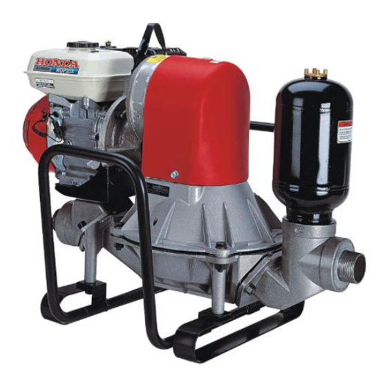
- Page 1 Owner’s Manual DIAPHRAGM PUMP WDP20X • WDP30X © 1996–2004 American Honda Motor Co., Inc.—All Rights Reserved...
- Page 2 WARNING: The engine exhaust from this product contains chemicals known to the State of California to cause cancer, birth defects or other reproductive harm. This owner's manual is considered a permanent part of your diaphragm pump. It must be available to all operators of the pump and should remain with the pump if resold.
- Page 3 INTRODUCTION Congratulations on your selection of a Honda diaphragm pump! We are certain you will be pleased with your purchase of one of the finest pumps on the market. We want to help you get the best results from your new pump and to operate it safely.
- Page 4 INTRODUCTION A FEW WORDS ABOUT SAFETY Your safety, and the safety of others, are very important. And using this pump safely is an important responsibility. To help you make informed decisions about safety, we have provided operating procedures and other information on labels and in this manual.
-
Page 5: Table Of Contents
CONTENTS PUMP SAFETY ......... . 6 IMPORTANT SAFETY INFORMATION . - Page 6 CONTENTS AIR FILTER INSPECTION ......30 AIR FILTER CLEANING ....... 31 SPARK PLUG SERVICE .
- Page 7 CONTENTS Maintenance ........66 Tune-up .
-
Page 8: Pump Safety
PUMP SAFETY This chapter explains what you need to know to operate your diaphragm pump safely. IMPORTANT SAFETY INFORMATION Honda WDP20X and WDP30X pumps are not designed to pump drinking water. Pump only non-potable water, muddy water, and water containing solids. Other uses can result in injury to the operator or damage to the pump and other property. -
Page 9: Hot Exhaust
PUMP SAFETY Hot Exhaust The muffler becomes very hot during operation and remains hot for a while after stopping the engine. Be careful not to touch the muffler while it is hot. Let the engine cool before transporting the pump or storing it indoors. -
Page 10: Safety Label Location
PUMP SAFETY SAFETY LABEL LOCATION The label shown here contains important safety information. Please read it carefully. This label is considered a permanent part of your pump. So if the label comes off or becomes hard to read, contact your authorized Honda pump dealer for a replacement. -
Page 11: Controls
CONTROLS This chapter shows you the locations of controls and other important parts of your pump, and tells you how the controls work. COMPONENT IDENTIFICATION PUMP GREASE FITING ACCESS PLUG THROTTLE LEVER SUCTION CHOKE PORT LEVER FUEL VALVE LEVER OIL FILLER STARTER CAP/DIPSTICK GRIP... -
Page 12: Description Of Controls
CONTROLS DESCRIPTION OF CONTROLS You will use these controls every time you operate your diaphragm pump. Throttle Lever THROTTLE LEVER The throttle lever controls the engine speed. Moving the throttle lever fully to the left gives IDLE maximum engine speed. Moving the throttle lever fully to the right returns the engine to idle speed. -
Page 13: Ignition Switch
CONTROLS Ignition Switch OIL ALERT LABEL The ignition switch allows the OIL ALERT OIL ALERT WHEN OIL LEVEL IS LOW WHEN OIL LEVEL IS LOW ENGINE STOPS IMMEDIATELY ENGINE STOPS IMMEDIATELY operator to start and stop the engine. Switch positions: OFF: To stop the engine. -
Page 14: Before Operation
BEFORE OPERATION This chapter tells you how to prepare your pump and yourself before you begin using the pump. ARE YOU READY TO GET STARTED? Your safety is your responsibility. A little time spent in preparation will significantly reduce your risk of injury. Knowledge Read and understand this manual. -
Page 15: Is Your Pump Ready To Go
BEFORE OPERATION IS YOUR PUMP READY TO GO? For your safety, and to maximize the service life of your equipment, it is very important to take a few moments before you operate the pump to check its condition. Be sure to take care of any problem you find, or have your servicing dealer correct it, before you operate the pump. -
Page 16: Check The Suction And Discharge Hoses
BEFORE OPERATION Check the Suction and Discharge Hoses • Check the general condition of the hoses. Be sure the hoses are in serviceable condition before connecting them to the pump. Remember that the suction hose must be of reinforced construction to prevent hose collapse. •... -
Page 17: Operation
OPERATION This chapter tells how to operate your pump safely and effectively. Read this chapter completely before operating the pump. Take time to familiarize yourself with the controls and how they operate. The small amount of time spent in familiarization will reward you with greater efficiency and reduced risk. - Page 18 OPERATION Due to the pump diaphragm reciprocating motion, pump assembly and hoses will move up and down and side-to-side during pumping. This may cause the pump to walk or move around while pumping. Depending on the surface conditions, pump hose length, and other factors, it may be necessary to anchor the pump to limit pump movement.
- Page 19 OPERATION When water being pumped contains solids, the solids may get lodged under the clappet valves, which will prevent the clappet valves from closing completely. To maintain maximum pump performance, the discharge hose should angle upward as it exits the pump. DISCHARGE HOSE If the discharge hose must run...
-
Page 20: Pump Preparation
OPERATION PUMP PREPARATION Suction Hose Connection Use a commercially available hose, hose connector, and hose clamps. The hose must be the same size or larger than the suction port. To prevent the hose from collapsing, use a hose that is reinforced with a noncollapsible wall or braided wire construction. -
Page 21: Discharge Hose Connection
OPERATION Discharge Hose Connection Use a commercially available hose, hose connector, and hose band. A short, large diameter hose will provide lower fluid friction and improve pump output. A long or small diameter hose will increase fluid friction and reduces pump output. Never use a hose size smaller than the discharge port diameter. -
Page 22: Starting The Engine
OPERATION STARTING THE ENGINE 1. Turn the fuel valve to the ON FUEL VALVE position. 2. Move the choke lever to the CHOKE LEVER CLOSED position. Do not use the choke if the engine is warm or the ambient temperature is high. CLOSED 3. - Page 23 OPERATION 5. Pull the starter grip lightly until resistance is felt, then pull it briskly. NOTICE Return the starter grip slowly back to the engine to prevent damage to the starter. STARTER GRIP 6. As the engine warms up, CHOKE LEVER gradually move the choke lever to the OPEN position.
-
Page 24: Stopping The Engine
OPERATION STOPPING THE ENGINE Emergency IGNITION To stop the engine in an SWITCH emergency, turn the ignition switch to the OFF position. Normal 1. Move the throttle lever fully to the right to the IDLE position. THROTTLE LEVER 2. Turn the ignition switch to the OFF position. -
Page 25: Servicing Your Pump
SERVICING YOUR PUMP This chapter explains when and how to perform routine inspection, service, and adjustments for do-it-yourself maintenance. More difficult maintenance tasks should be done by your dealer. Your dealer is best equipped and staffed to provide the level of service and safety you and your pump deserve. -
Page 26: Maintenance Safety
SERVICING YOUR PUMP MAINTENANCE SAFETY Some of the most important safety precautions follow. However, we cannot warn you of every conceivable hazard that can arise in performing maintenance. Only you can decide whether or not you should perform a given task. WARNING Failure to properly follow maintenance instructions and precautions can cause you to... -
Page 27: Maintenance Schedule
SERVICING YOUR PUMP MAINTENANCE SCHEDULE REGULAR SERVICE PERIOD (4) Perform at every indicated month or operating hour interval, ITEM whichever comes first. Check level Engine oil Change Check Air cleaner Clean O(1) Replace O*(1) Check-adjust Spark plug Replace Spark arrester Clean O(3) (optional equipment) -
Page 28: Engine Oil Level Check
SERVICING YOUR PUMP ENGINE OIL LEVEL CHECK Check the engine oil level with the engine stopped and in a level position. 1. Remove the filler cap/dipstick and wipe it clean. FILLER CAP/DIPSTICK 2. Insert and remove the dipstick without screwing it into the filler neck. -
Page 29: Engine Oil Change
SERVICING YOUR PUMP ENGINE OIL CHANGE Drain the oil while the engine is warm. Warm oil drains quickly and completely. 1. Remove the oil filler/dipstick cap, drain bolt and sealing washer. Drain the oil into a suitable container. OIL FILLER/ CONTAINER DIPSTICK SEALING... - Page 30 SERVICING YOUR PUMP 3. Fill with the recommended oil to the top of the oil filler neck (see page 29). NOTICE Using nondetergent oil can shorten the engine's service life, and using 2-stroke oil can damage the engine. 4. Screw in the oil filler cap/dipstick securely. UPPER LIMIT MARK FILLER/DIPSTICK CAP...
-
Page 31: Engine Oil Recommendations
SERVICING YOUR PUMP ENGINE OIL RECOMMENDATIONS Oil is a major factor affecting performance and service life. Use 4-stroke automotive detergent oil. SAE 10W-30 is recommended for general use. Other viscosities shown in the chart may be used when the average temperature in your area is within the recommended range. -
Page 32: Air Filter Inspection
SERVICING YOUR PUMP AIR FILTER INSPECTION 1. Unscrew the OUTER outer wing nut WING NUT and remove the air cleaner cover. 2. Remove the AIR CLEANER COVER inner wing nut and both air filter elements. INNER WING NUT 3. Separate both air filter elements PAPER FILTER and carefully... -
Page 33: Air Filter Cleaning
SERVICING YOUR PUMP AIR FILTER CLEANING A dirty air filter will restrict air flow to the carburetor, reducing engine performance. If you operate the pump in very dusty areas, clean the air filter more often than specified in the MAINTENANCE SCHEDULE. 1. -
Page 34: Spark Plug Service
SERVICING YOUR PUMP SPARK PLUG SERVICE Recommended spark plugs: NGK – BPR6ES DENSO – W20EPR-U NOTICE Spark plugs of the wrong size or incorrect heat range can cause engine damage. For good performance, the spark plug must be properly gapped and free of deposits. - Page 35 SERVICING YOUR PUMP 5. Check that the spark plug washer is in good condition, and thread the spark plug in by hand to prevent cross-threading. 6. After the spark plug is seated, tighten with a spark plug wrench to compress the washer. If installing a new spark plug, tighten 1/2 turn after the spark plug seats to compress the...
-
Page 36: Spark Arrester Service (Optional Equipment)
SERVICING YOUR PUMP SPARK ARRESTER SERVICE (optional equipment) The spark arrester must be serviced every 100 hours to keep it functioning as designed. 1. Allow the engine to cool, then remove the two 8 mm nuts and remove the muffler from the cylinder head. 2. -
Page 37: Refueling
SERVICING YOUR PUMP REFUELING Fuel tank capacity: 0.66 US gal (2.5 ) Refuel in a well-ventilated area with the engine stopped. If the engine has been running, allow it to cool. Refer to page 36 for fuel recommendations and page 61 for information about oxygenated fuels. -
Page 38: Fuel Recommendations
SERVICING YOUR PUMP FUEL RECOMMENDATIONS Use unleaded gasoline with a pump octane rating of 86 or higher. This engine is certified to operate on unleaded gasoline. Unleaded gasoline produces fewer engine and spark plug deposits and extends exhaust system life. Never use stale or contaminated gasoline or oil/gasoline mixture. -
Page 39: Carburetor Adjustment
SERVICING YOUR PUMP CARBURETOR ADJUSTMENT 1. Start the engine outdoors and let it warm up to normal operating temperature. 2. Move the throttle lever to the slowest position. 3. Using a screwdriver, turn the throttle stop screw to obtain the standard idle speed. -
Page 40: Fuel Filter/Fuel Line
SERVICING YOUR PUMP FUEL FILTER/FUEL LINE 1. Turn the fuel valve to the OFF FUEL VALVE position. 2. Remove the carburetor drain screw and gasket. 3. Turn the fuel valve to the ON GASKET position and drain the fuel into a suitable container. -
Page 41: Pump Chamber Flushing
SERVICING YOUR PUMP PUMP CHAMBER FLUSHING With the engine stopped, the pump case should be flushed after each use to prevent sediment from building up in the case. 1. Disconnect the suction and discharge hoses. 2. Insert a garden hose into the suction side of the pump. Turn on the water and thoroughly flush sediment out the discharge side. -
Page 42: Grease The Pump Connecting Rod
SERVICING YOUR PUMP GREASE THE PUMP CONNECTING ROD 1. Remove the plastic access plug. 2. Disconnect the spark plug cap and pull the recoil starter until the grease fitting is below the access opening. 3. Wipe the grease fitting clean to prevent dirt from getting into the bearing. -
Page 43: Pump Gear Box Oil Change
SERVICING YOUR PUMP PUMP GEAR BOX OIL CHANGE 1. Run the engine for 10 minutes to warm up the gear box oil. Warm oil drains quickly and completely. 2. Shut off the engine. 3. Remove the two 8x16 mm bolts from the connecting rod cover and remove the cover. - Page 44 SERVICING YOUR PUMP 4. Remove the drain bolt and drain the gear oil from the gear box. OIL FILLER CAP/ DIPSTICK UPPER LIMIT LOWER LIMIT WASHER WASHER DRAIN BOLT 5. Replace the drain bolt washer and reinstall the drain bolt. 6.
-
Page 45: Pump Clappet Valves
SERVICING YOUR PUMP PUMP CLAPPET VALVES 1. Disconnect the spark plug cap from the spark plug, refer to page 32. 2. Turn the fuel valve lever to the OFF position, refer to page 10. 3. Flush the pump chamber, refer to page 39. - Page 46 SERVICING YOUR PUMP 9. Install the clappet valves over the studs. On the discharge side, the flat side of the valve should face the housing. On the suction side, the flat side of the valve should face the port. PORT CLAPPET VALVE TABS 10.
-
Page 47: Pump Diaphragm Disassembly
SERVICING YOUR PUMP PUMP DIAPHRAGM DISASSEMBLY 1. Disconnect the spark plug cap from the spark plug, refer to page 32. 2. Drain the fuel tank, refer to page 38 for fuel tank draining. 3. Flush the pump chamber, refer to page 39. 4. - Page 48 SERVICING YOUR PUMP 7. Remove the connecting rod plastic cover. 8. Use a 17 mm wrench and remove the bolt securing the connecting rod to the crank arm. Wipe the rod surface clean and use a felt tip marker to mark the outside of the connecting rod for reassembly. NYLON WASHER CRANK...
- Page 49 SERVICING YOUR PUMP 11. If the diaphragm is to be NUT (4) reused, mark the diaphragm to allow it to be WASHER (4) installed in the same position. With a 19 mm DIAPHRAGM wrench, remove the four nuts securing the SHOULDER connecting rod to the lower flange.
-
Page 50: Pump Diaphragm Reassembly
SERVICING YOUR PUMP PUMP DIAPHRAGM REASSEMBLY During reassembly, note the following: • Apply several drops of Hondalock 2 or equivalent thread lock to bolt threads. • To prevent pump case and/or diaphragm damage, follow the torque sequence shown below. Torque: Start in one corner, increasing the amount or torque 1/8 to 1/4 turn each time around until the specified torque is achieved. - Page 51 SERVICING YOUR PUMP 1. Position the diaphragm between the connecting rod flange and the lower flange, then install the nuts and washers. Note the diaphragm shoulder on top. See page 48 for tightening torque. NUT (4) WASHER (4) DIAPHRAGM DIAPHRAGM SHOULDER LOWER FLANGE...
- Page 52 SERVICING YOUR PUMP 5. Pull the recoil starter slowly until the diaphragm pulls up against the upper case stops. UPPER UPPER CASE CASE STOP (4) DIAPHRAGM The crank arm should be approximately at the angle shown below. CRANK 6. Install the lower case, making sure the diaphragm is centered and not pinched between the case stops.
-
Page 53: Storage
STORAGE This chapter tells you how to protect your pump and ensure that it will start easily when you want to use it again. STORAGE PREPARATION The following steps will help to keep rust and corrosion from impairing your pump's function and appearance, and will make the engine easier to start when you use the pump again. -
Page 54: Fuel
STORAGE Fuel Gasoline will oxidize and deteriorate in storage. Old gasoline will cause hard starting, and it leaves gum deposits that clog the fuel system. If the gasoline in your pump's engine deteriorates during storage, you may need to have the carburetor and other fuel system components serviced or replaced. - Page 55 STORAGE Draining the Fuel Tank and Carburetor 1. Remove the carburetor drain screw with a 10 mm wrench or screwdriver, and drain the fuel system into an approved gasoline container. WARNING Gasoline is highly flammable and explosive. You can be burned or seriously injured when handling fuel.
-
Page 56: Engine Oil
STORAGE Engine Oil 1. Change the engine oil (see page 27). 2. Check the air filter and clean as necessary (see page 30). 3. Remove the spark plug (see page 32). 4. Pour a tablespoon (5 - 10 cc) of clean engine oil into the cylinder. 5. -
Page 57: Placing In Storage
STORAGE PLACING IN STORAGE If your pump will be stored with gasoline in the fuel tank and carburetor, it is important to reduce the hazard of gasoline vapor ignition. Select a well ventilated storage area away from any appliance that operates with a flame, such as a furnace, water heater, or clothes dryer. -
Page 58: Transporting
TRANSPORTING This chapter explains how to load and carry your pump safely. BEFORE LOADING When transporting the pump, be sure to keep it upright. If the pump is tilted or overturned, fuel may spill from the tank, which can result in a fire hazard. -
Page 59: Taking Care Of Problems
TAKING CARE OF PROBLEMS This chapter tells you what to check for if you encounter problems with your pump. ENGINE WILL NOT START Fuel 1. Is there enough fuel in the fuel FUEL tank? (page 35). VALVE 2. Is the fuel valve ON? DRAIN 3. - Page 60 TAKING CARE OF PROBLEMS 7. Does the pump require priming? (page 19). 8. Is debris under the clappet valves or are the valves damaged? (page 43). 9. Is the diaphragm torn? (page 45). 10. If the pump still does not pump, take the pump to an authorized Honda servicing dealer.
-
Page 61: Technical And Consumer Information
TECHNICAL AND CONSUMER INFORMATION This chapter gives you dimensions, capacities, and other technical information. TECHNICAL INFORMATION Serial Number Locations FRAME SERIAL NUMBER ENGINE SERIAL NUMBER Record the frame and engine serial numbers in the space below. You will need these serial numbers when ordering parts and when making technical or warranty inquiries (see page 73). -
Page 62: Carburetor Modification For High Altitude Operation
TECHNICAL AND CONSUMER INFORMATION Carburetor Modification for High Altitude Operation At high altitude, the standard carburetor air fuel mixture will be too rich. Performance will decrease, and fuel consumption will increase. A very rich mixture will also foul the spark plug and cause hard starting. Operation at an altitude that differs from that at which this engine was certified, for extended periods of time, may increase emissions. -
Page 63: Oxygenated Fuels
TECHNICAL AND CONSUMER INFORMATION Oxygenated Fuels Some conventional gasolines are being blended with alcohol or an ether compound. These gasolines are collectively referred to as oxygenated fuels. To meet clean air standards, some areas of the United States and Canada use oxygenated fuels to help reduce emissions. -
Page 64: Emission Control System
TECHNICAL AND CONSUMER INFORMATION EMISSION CONTROL SYSTEM Source of Emissions The combustion process produces carbon monoxide, oxides of nitrogen, and hydrocarbons. Control of hydrocarbons and oxides of nitrogen is very important because, under certain conditions, they react to form photochemical smog when subjected to sunlight. Carbon monoxide does not react in the same way, but it is toxic. - Page 65 TECHNICAL AND CONSUMER INFORMATION Replacement Parts The emission control systems on your new Honda engine were designed, built, and certified to conform with EPA and California emission regulations. We recommend the use of genuine Honda parts whenever you have maintenance done. These original-design replacement parts are manufactured to the same standards as the original parts, so you can be confident of their performance.
- Page 66 TECHNICAL AND CONSUMER INFORMATION Air Index An Air Index Information hang tag/label is applied to engines certified to an emission durability time period in accordance with the requirements of the California Air Resources Board. The bar graph is intended to provide you, our customer, the ability to compare the emissions performance of available engines.
-
Page 67: Specifications
TECHNICAL AND CONSUMER INFORMATION SPECIFICATIONS Dimensions and Weight Model WDP20XTA WDP30XTA Description code WZBZ WZCA Length x Width x Height 32.5 x 23.4 x 25.0 in (826 x 594 x 635 mm) Dry weight 120 lbs (54.4 kg) Engine Design and Performance Model GX120T1QX2 Engine type... -
Page 68: Gear Box
TECHNICAL AND CONSUMER INFORMATION Gear Box Pump operating frequency 73 strokes/min. Gear reduction 43:1 Pump stroke 2.56 in (65.0 mm) 2.77 in (70.4 mm) Gear box oil capacity 0.8 qt (0.8 ) Gear box oil type 80W/90 GL5 gear oil Maintenance Unleaded gasoline with a Fuel... -
Page 69: Pump Performance Curve
TECHNICAL AND CONSUMER INFORMATION Pump Performance Curve This graph shows the relationship between the pump discharge capacity and the total dynamic head, based on clear water at sea level. As you increase the total head, the discharge capacity will decrease. Wiring Diagram ENGINE IGNITION... -
Page 70: Consumer Information
TECHNICAL AND CONSUMER INFORMATION CONSUMER INFORMATION This chapter contains additional information, Honda publications available to you, and tells you how to contact us if you have a question or a warranty repair problem. Honda Publications This publication will give you additional information about maintaining your pump. -
Page 71: Distributor's Limited Warranty
Honda Power Equipment dealer in the United States, Puerto Rico, or the U.S. Virgin Islands who is authorized to sell that product, during the dealer’s normal business hours. -
Page 72: Emission Control System Warranty
Emission Control System Warranty Your new Honda Power Equipment engine complies with both the U.S. EPA and State of California emission regulations. American Honda provides the same emission warranty coverage for engines sold in all 50 states. - Page 73 To Obtain Warranty Service: You must take your Honda Power Equipment engine or the product on which it is installed, along with your sales registration card or other proof of original purchase date, at your expense, to any Honda Power Equipment dealer who is authorized by American Honda Motor Co., Inc., to sell...
- Page 74 TECHNICAL AND CONSUMER INFORMATION Exclusions: FAILURES OTHER THAN THOSE RESULTING FROM DEFECTS IN MATERIAL OR WORKMANSHIP ARE NOT COVERED BY THIS WARRANTY. THIS WARRANTY DOES NOT EXTEND TO EMISSION CONTROL SYSTEMS OR PARTS WHICH ARE AFFECTED OR DAMAGED BY OWNER ABUSE, NEGLECT, IMPROPER MAINTENANCE, MISUSE, MISFUELING, IMPROPER STORAGE, ACCIDENT AND/OR COLLISION, THE INCORPORATION OF, OR ANY USE OF, ANY ADD-ON OR MODIFIED PARTS, UNSUITABLE ATTACHMENTS, OR THE UNAUTHORIZED ALTERATION OF ANY PART.
-
Page 75: Customer Service Information
TECHNICAL AND CONSUMER INFORMATION Customer Service Information Honda power equipment dealership personnel are trained professionals. They should be able to answer any question you may have. If you encounter a problem that your dealer does not solve to your satisfaction, please discuss it with the dealership's management. -
Page 76: Index
INDEX Air Cleaner Maintenance Safety ......24 Clean ..........31 Maintenance Schedule ..... 25 Inspect ........... 30 Air Index ........... 64 Oil Alert System ....... 11 Oil, Engine Before Operation ......12 Change .......... 27 Level Check ........28 Recommendations ......29 Carburetor High Altitude Operation .... - Page 77 INDEX Throttle Lever ........10 Transporting Your Pump ....56 Troubleshooting Engine Will Not Start ..... 57 Pump Will Not Pump ..... 57 Warranty Service Information ... 73 Warranty, Emissions ......70 Wiring Diagram ........ 67...
-
Page 79: Quick Reference Information
QUICK REFERENCE INFORMATION Unleaded gasoline with pump Type octane rating of 86 or higher Fuel (page 36). Capacity 0.66 US gallons (2.5 ) SAE 10W-30, API SH, SJ, or SL Type (page 29) Engine Oil Capacity 0.6 US quarts (0.6 ) Resistor: Type NGK –... - Page 80 POM52831-B 1000.2004.04 31TDP601 Printed on PRINTED IN U.S.A. 00X31-TDP-6010 Recycled Paper...
Need help?
Do you have a question about the WDP20X and is the answer not in the manual?
Questions and answers