
Related Manuals for COMFORT-AIRE Comfort-Cire RAD-183A


Summary of Contents for COMFORT-AIRE Comfort-Cire RAD-183A
-
Page 1: Service Manual
AD-183A AD-243A SERVICE MANUAL CAUTION • BEFORE SERVICING THE UNIT, READ THE SAFETY PRECAUTIONS IN THIS MANUAL. • ONLY FOR AUTHORIZED SERVICE PERSONNEL. -
Page 2: Table Of Contents
Air Conditioner Service Manual TABLE OF CONTENTS Safety Precautions............................3 Dimensions ..............................5 Symbols Used in this Manual ........................5 Outside Dimensions ...........................5 Product Specifications ..........................6 Installation ...............................7 Select the Best Location ...........................7 Installation Check ............................7 How to Secure the Drain Pipe ........................7 Window Requirements ..........................8 Installation Kits Contents..........................8 Suggested Tool Requirements ........................9... -
Page 3: Safety Precautions
Safety Precautions Safety Precautions To prevent injury to the user or other people and property damage, the following instructions must be followed. Incorrect operation due to ignoring instruction will cause harm or damage. The seriousness is classified by the following indications. WARNING This symbol indicates the possibility of death or serious injury. - Page 4 Safety Precautions Do not modify or extend the power cord. Do not install, remove, or re-install the unit by yourself. • There is risk or fire or electric shock. • There is risk of fire, electric shock, explosion, or injury. Be cautious when unpacking and installing Do not store or use flammable gas or com- the product.
-
Page 5: Dimensions
Dimensions Dimensions Symbols Used in this Manual This symbol alerts you to the risk of electric shock. This symbol alerts you to hazards that could cause harm to the air conditioner. This symbol indicates special notes. NOTICE Outside Dimensions Model 18K Btu 24K Btu Dimension... - Page 6 Specfications Product Specifications Table -1 MODELS RAD-183A ITEMS POWER SUPPLY 1Ø, 208/230V, 60Hz COOLING CAPACITY 17,500/18,000 INPUT 1,800/1,850 9.0/8.3 E.E.R REFRIGERANT (R-22) CHARGE(g) 720g(25.4oz) OPERATING INDOOR(°C) 27(DB),19(WB) TEMPERATURE OUTDOOR(°C) 35(DB),24(WB) EVAPORATOR 2 ROW 15 STACKS LOUVERED-FIN TYP CONDENSER 2 ROW 19 STACKS,LOUVERED-FIN TYPE L-BENDING TYPE FAN, INDOOR TURBO...
-
Page 7: Product Specifications
Specfications Product Specifications Table -1 MODELS RAD-243A ITEMS POWER SUPPLY 1Ø, 208/230V, 60Hz COOLING CAPACITY 23,500/23,000 INPUT 2,760/1,850 E.E.R 8.5/8.5 REFRIGERANT (R-22) CHARGE(g) 830g(29.3oz) OPERATING INDOOR(°C) 27(DB),19(WB) TEMPERATURE OUTDOOR(°C) 35(DB),24(WB) EVAPORATOR 3 ROW 15 STACKS LOUVERED-FIN TYP CONDENSER 2 ROW 19 STACKS,LOUVERED-FIN TYPE L-BENDING TYPE FAN, INDOOR TURBO... -
Page 8: Installation
Installation Installation Select the Best Location 1.To prevent vibration and noise, make sure the unit is installed securely and firmly. 2.Install the unit where the sunlight does not shine directly FENCE on the unit. AWNING 3.The outside of the cabinet must extend outward for at COOLED AIR least 30cm and there should be no obstacles, such as a HEAT... -
Page 9: Window Requirements
Installation Window Requirements All supporting parts should be secured to firm NOTICE wood, masonry, or metal. 26" to 41" 1. This unit is designed for installation in standard dou- ble hung windows with actual opening widths from 18" min Stool 26"... -
Page 10: Suggested Tool Requirements
Installation Suggested Tool Requirements PREPARATION OF CHASSIS Shipping screws 1. Remove the screws which fasten the cabinet at both sides and at the back. Figure 2 2. Slide the unit out from the cabinet by gripping the base pan handle and pulling forward while bracing the cabinet. -
Page 11: Cabinet Installation
Installation Cabinet Installation 1. Open the window. Mark a line on the center of the window stool between the side window stop mold- Sill Bracket ings. Support Bracket Loosely attach the sill bracket to the support bracket Carriage using the carriage bolt and the lock nut. Lock nut Bolt (M-Screw) - Page 12 Installation 5. Pull each Frame curtain fully to each window sash track, and pull the bottom window sash down behind the Top retainer bar until it meets. 6. Attach each Frame curtain the window sash by using screws (Type C.) (See Fig. 11) Figure 11 7.
-
Page 13: Operation
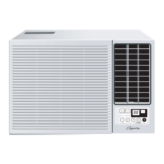
Operation Operation Features • Designed for COOLING ONLY. • Powerful and whispering cooling. • Built-in adjustable THERMOSTAT • Slide-in and slide-out chassis for the simple instal- • Washable one-touch filter lation and service. • Compact size • Side air-intake, side cooled-air discharge. •... - Page 14 Operation 2. Cooling Only Model with Remote Control and Touch Type DISPLAY REMOTE CONTROL RAD-183A RAD-183A, RAD-243A RAD-243A Power Temp Fan Speed Timer Mode Energy Auto Saver Swing PRECAUTION: The Remote Control unit will not function properly if bright light strikes the sensor window of the air conditioner or if there are obstacles between the Remote Control unit and the air conditioner.
-
Page 15: Disassembly
Disassembly Disassembly — Before the following disassembly, CONTROL BOX set to OFF and disconnect the power cord. Mechanical Parts 1. Front Grille 1. Open the lnlet grille upward . 2. Remove the screw that fastens the front grille. 3. Pull the front grille from the right side. 4. -
Page 16: Air Handling Parts
Disassembly Air Handling Parts 4. Cover (at the top) 1. Remove the front grille. (Refer to section 17) 2. Remove the cabinet. (Refer to section 18) 3. Remove 11 screws which fasten the brace and covers. 4. Remove the covers and the brace. (See Fig. 20) 5. -
Page 17: Electrical Parts
Disassembly 6. Shroud 1. Remove the fan. (Refer to section 21) 2. Remove the screw that fastens the shroud. 3. Remove the shroud. (See Figure 24) 4. Re-install the component by referring to the removal procedure, above. Figure 24 Electrical Parts 7. -
Page 18: Synchronous Motor
Disassembly 9. Capacitor 1. Remove the control box. (Refer to section 19) 2. Remove the knobs and the screw that fasten control panel from control box. 3. Remove the screw that located in the front. 4. Open the bottom side of control box. 5. -
Page 19: Refrigerating Cycle
Disassembly Refrigerating Cycle CAUTION: Discharge the refrigerant system using a Freon Recovery System. If there is no valve to attach the recovery system, install one (such as a WATCO A-1) before venting the Freon Leave the valve in place after servicing the system. - Page 20 Disassembly NOTICE — Replacement of the refrigeration cycle. 6. Recharge as follows : 1. When replacing the refrigeration cycle, be sure to Discharge the refrigerant system using a Freon 1) Refrigeration cycle systems are charged from the recovery System. High-side. If the total charge cannot be put If there is no valve to attach the recovery system, in the High-side, the balance will be put in the install one (such as a WATCO A-1) before venting...
- Page 21 Disassembly Equipment needed: Vacuum pump, Charging cylinder, Manifold gauge, Brazing equipment. Pin-off tool capable of making a leak-proof seal, Leak detector, Tubing cutter, Hand Tools to remove components, Service valve. Figure 33B-Charging Figure 33A-Pulling Vacuum 21 Room Air Conditioner...
-
Page 22: Schematic Diagram
Schematic Diagram Schematic Diagram Electronic Control Device SEG-d TEST SEG-e SEG-f /Reset SEG-g SLIDE VAref KEY0 Room KEY1 Pipe out0 Option1 out1 out2 Option2 Service Manual 22... -
Page 23: Wiring Diagram
Schematic Diagram Wiring Diagram • MODEL : RAD-183A and RAD-243A POWER INPUT WH(BL) BK(BR) (Ribbed) (Plain) GN/YL(GN) THERMISTOR CN-TH1 MOTOR OR(BR) OR(BR) GN/YL (GN) CAPACITOR OR(BR) SYNC MOTOR RY-SYNC RY-COMP COMP. TRANS FORMER FUSE 250V/T2A (115V/T2A) 3854AR2330P WIRING DIAGRAM 23 Room Air Conditioner... -
Page 24: Components Lation
Schematic Diagram Components Location Main P.W.B Assembly Display P.W.B Assembly Service Manual 24... -
Page 25: Troubleshooting Guide
Troubleshooting Guide Troubleshooting Guide Piping System CONDENSER COIL CAPILLARY TUBE MOTOR COMPRESSOR BLOWER EVAPORATOR COIL Figure 34 is a brief description of the important components and their function in what is called the refrigeration system. This will help you to understand the refrigeration cycle and the flow of the refrigerant in the cooling cycle. ROOM AIR CONITIONER CYCLE OF REFRIGERATION EVAPORATOR COILS... -
Page 26: Troubleshooting Guide
Troubleshooting Guide Troubleshooting Guide In general, possible trouble is classified in two kinds. The one is called Starting Failure which is caused from an electrical defect, and the other is ineffective Air Conditioning caused by a defect in the refrigeration circuit and improper application. Unit runs but poor cooling. - Page 27 Troubleshooting Guide Fails to Start Check of power source. Check circuit breaker and fuse. Check of control switch Gas leakage of feeler bulb setting. of thermostat Check of control switch. Compressor only fails to Fan only fails to start. start. Improper wiring.
-
Page 28: Electrical Parts Troubleshooting Guide
Troubleshooting Guide Electrical Parts Troubleshooting Guide Possible Trouble 1 The unit does not operate. • Check the Fuse. Is the Trans output power • Check the wiring diagram. AC 220V? • Check the Main Is the Trans output power Is shorted the Trans. output? PCB pattern. - Page 29 Troubleshooting Guide Possible Trouble 2 The compressor does not operate. Is setting • Select the setting Temp. to lower Number. Temp. set lower than Room Temp.-0.5 C? Is the voltage No.10 Is the voltage N0.7 of Is the Unit for 3 minutes of IC01M 0V? IC01M DC 5V? delay?
- Page 30 Troubleshooting Guide Possible Trouble 4 FAN does not operate. Is the voltage NO.1 or 4 • Exchange IC01M. of IC01M DC 5V? Is the voltage NO.13 or 16 • Exchange IC01M. of IC01M 0V? • Check the RY-Hi or RY-Lo. •...
- Page 31 Troubleshooting Guide Possible Trouble 6 Remote controller does not operate. Is the voltage of Battery • Exchange the battery. about over 2.3V? Is the voltage No.16 • Check the PCB pattern. of CN-DISP on Main PCB Ass'y DC 5V? • Connect connector to Is the connection of CN-DISP exactly.
-
Page 32: Room Air Conditioner Voltage Limits
Troubleshooting Guide Room Air Conditioner Voltage Limits NAME PLATE RATING MINIMUM MAXIMUM 208~230±10% 187V 253V 115±10% 104V 126V COMPLAINT CAUSE REMEDY Fan motor will not run. No power Check voltage at outlet. Correct if necessary. Power supply cord Check voltage to rotary switch. If none, check power supply cord. - Page 33 Troubleshooting Guide COMPLAINT CAUSE REMEDY Thermostat Compressor will not run, Check the position of knob If not at the coldest set- but fan motor runs. ting, advance the knob to this setting and restart unit. Check continuity of the thermostat. Replace ther- mostat if circuit is open.
- Page 34 Troubleshooting Guide REMEDY COMPLAINT CAUSE Capacitor Compressor cycles Test capacitor. on overload. Wiring Check the terminals. If loose, repair or replace. Refrigerating system Check the system for a restriction. Air filter If restricted, clean of replace. Insufficient cooling or heat- Exhaust damper door Close if open.
- Page 35 Exploded View Exploded View Cooling Model 554031 148000 130910 W48602 559011 149980 749750 349600 130410 346811 554160 359012 550140 349480 354210 325115-1 325115-2 147582 349001 W48602 552111 267110 352113 552113 249950 135312 567480 35211A W0CZZ 159830 249950 135314 268711-1 269310 137215 238310 135510...
- Page 36 Replacement Parts List RAD-183A LocNo P/NO REMARK DESCRIPTION 130410 3041A30001H BASEASSEMBLY,SINGLE 130910 3091AR6056P CABINETASSY,SINGLE 135312 AEB30969401 Grille,ASSY,Front(SINGLE) 135314 3530AR1604A Grille,ASSY,INLET 135510 3551A30001A COVER,CONTROL(INDOOR) 146812 2H01102J MotorAssembly,SYNC 147581-1 4758AR7264A LOUVER,HORIZONTAL 147581-2 4758AR7278A LOUVER,HORIZONTAL 147582 4758AR6157A LOUVER,VERTICAL 148000 4800AR7271A BRACE 149980 4998AR1597B SHROUD 159830 5231AR6159A...
- Page 37 Replacement Parts List RAD-243A LocNo P/NO REMARK DESCRIPTION 130410 3041A30001F BASE ASSEMBLY,SINGLE 130910 3091AR6056P CABINET ASSY,SINGLE 135312 AEB30969401 Grille ASSY,Front(SINGLE) 135314 3530AR1604A Grille ASSY,INLET 135510 3550AR7046D COVER,CONTROL(INDOOR) 146812 2H01102J Motor Assembly,SYNC 147581-1 4758AR7264A LOUVER,HORIZONTAL 147581-2 4758AR7278A LOUVER,HORIZONTAL 147582 4758AR6157A LOUVER,VERTICAL 148000 4800AR7271A BRACE...
- Page 38 04/18/07...
Need help?
Do you have a question about the Comfort-Cire RAD-183A and is the answer not in the manual?
Questions and answers