Table of Contents
Advertisement
Quick Links
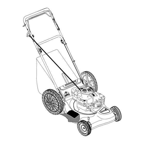
Operator's Manual
21" Self Propelled
Mulching Mower
Model 567
IMPORTANT:
Read safety rules and instructions
carefully
before operating
equipment.
Warning:
This unit is equipped with an internal combustion engine and should not be used on or near any unimproved forest-
covered, brush-covered
or grass-covered
land unless the engine's exhaust system is equipped with a spark arrester meeting
applicable
local or state laws (if any). If a spark arrester is used, it should be maintained in effective working order by the operator.
In the State of California the above is required by law (Section 4442 of the California Public Resources Code). Other states may have
similar laws. Federal laws apply on federal lands. A spark arrester for the muffler is available through your nearest engine authorized
service dealer or contact the service department,
P.O. Box 361131 Cleveland, Ohio 44136-0019.
MTD LLC, P.O.BOX361131CLEVELAND,0HI0 44136-0019
PRINTED IN U.S.A.
FORM
NO.
769-00981
(11/2003)
Advertisement
Chapters
Table of Contents

Related Manuals for Yard-Man 567


Summary of Contents for Yard-Man 567
- Page 1 Operator's Manual 21" Self Propelled Mulching Mower Model 567 IMPORTANT: Read safety rules and instructions carefully before operating equipment. Warning: This unit is equipped with an internal combustion engine and should not be used on or near any unimproved forest- covered, brush-covered or grass-covered land unless the engine's exhaust system is equipped with a spark arrester meeting...
-
Page 2: Table Of Contents
This information will be necessary to use the manufacturer's web site and/or help from the Customer Support Department or an authorized service dealer. Copy the model number here: YaRD-MaN,I( P o°ox = o,,=, Copy the serial number here: CLEVELAND,OH 44136 vwwv.yardman.com... -
Page 3: Important Safe Operation Practices
SECTION 1: IMPORTANT SAFEOPERATION P RACTICES WARNING" This symbol points out important safety instructions which, if not followed, could endanger the personal safety and/or property of yourself and others. Read and follow all instructions in this manual before attempting to operate this machine. Failure to comply with these instructions may result in personal injury. - Page 4 yourfooting, r elease thebladecontrol handle Do not mow slopes greater than 15 degrees as immediately andtheblade willstoprotating within shown on the slope gauge. threeseconds. Do not mow on wet grass. Unstable footing could 9. Mowindaylight o rgoodartificial light; w alk,notrun. cause slipping.
- Page 5 9. Never r emove gascapor addfuelwhiletheengine lead to improper performance and compromise ishotor running. Allowengine tocool a tleast t wo safety!" minutes b efore refueling. Mower blades are sharp and can cut. Wrap the 10.Never o verfill f ueltank.Filltanktonomorethan½ blade or wear gloves, and use extra caution when inchbelowbottom offillernecktoprovide space for servicing them.
- Page 6 SIGHT AND HOLD THIS LEVEL WITH A VERTICAL TREE i,II A POWER POLE A CORNER OF A BUILDING 15 ° WARNING Do not mow on inclines with a slope in excess of 15 degrees (a rise of approximately 2-1/2 feet every 10 feet), A riding mower could overturn and cause serious injury, If operating a walk-behind mower on such a slope, it is extremely difficult to maintain your footing and you could slip, resulting in serious injury.
-
Page 7: Assembling Your Lawn Mower
SECTION 3: ASSEMBLING YOUR LAWNMOWER Raise the lower handle in the direction shown in Removing UnitFromCarton Figure 1 (step 2) till it snaps into place. • Remove staples, break glue on top flaps, or cut Raise the upper handle in the direction shown in tape at carton end and peel along top flap to open. - Page 8 Attaching S tarterRope The rope guide is already attached to the right side of grass clippings, make sure the hooks on the ARNING: When using the mower to bag the upper handle of your mower. See Figure 4. grass catcher are firmly seated on the chute •...
-
Page 9: Know Your Lawn Mower
Converting To Mulcher Do not remove the side mulching plug at any time, even when you are not mulching. • Lift the rear discharge door on the mower and lift the grass catcher up. Release the discharge door Mulching Plug to allow it to close the rear opening of the mower. - Page 10 SECTION 5: OPERATING Y OUR LAWNMOWER NOTE: See page 23 of this manual for more detailed instructions on starting the engine. WARNING" Read and understand all instructions and warnings on the machine and ToStopEngine in this manual before operating. • Release the blade control handle to stop the engine Gas&...
-
Page 11: Maintaining Your Lawn Mower
SECTION 6: MAINTAINING YOUR LAWNMOWER WARNING: Avoid muffler and surrounding areas while the mower engine is hot because WARNING" disconnect the spark plug wire before Always stop the engine and temperature of these areas of the engine may performing any maintenance work or exceed 150 °... - Page 12 Engine To ReplaceBlade: • Follow the engine manual instructions at the end of • Before reinstalling the blade-pulley assembly to the this manual and recommended schedule for unit, lubricate the engine crankshaft and the inner lubricating engine components. surface of the blade adapter with light oil. •...
-
Page 13: Service & Adjustments
SECTION 7: SERVICE & ADJUSTMENTS Replacing D rive Belt Tighten the screw, loosened earlier, to secure the belt tension spring to the transmission, and • Remove two shoulder screws securing the front reassemble the front drive cover. drive cover to the mower deck. See Figure 12. Right Front Left Front Wheel... -
Page 14: Off Season Storage
For rough or uneven lawns, move the height adjustment handles to higher cutting height position. Height Adjustment Lever Notch Lower Handle Figure 15 Reassemble the upper handle to the lower handle. Place the hairpin clips in the inner holes of the weld pins and replace the carriage bolts and wing nuts Figure 16 on the handle brackets. - Page 15 SECTION 9: TROUBLE-SHOOTING Problem Possible Cause Corrective Action Engine fails to start Blade control handle disengaged Engage blade control handle. Spark plug wire disconnected Connect wire to spark plug. Fuel tank empty, or stale fuel Fill up tank with fresh gasoline. Blocked fuel line Clean fuel line.
- Page 16 SECTION 10: PARTS LISTFORMODEL 567 \\\\\\\ \\\\ IMPORTANT: For a proper working machine, use Factory Approved Parts. V-BELTS are specially designed to engage disengage safely. substitute (non OEM) V-Belt can be dangerous not disengaging completely.
- Page 17 Model567 Ref. No Ref. No Part No. Part No. Description Description 747-1214 Lower Bail Handle 710-1257 Hex Screw 3/8-24 x 2.50 710-0599 TT Screw 1/4-20 x 0.5 749-0928A Lower Handle 736-0270 Bell Washer.265 x 0.75 720-0426 Adjustment Knob 17032A 732-04089 Deflector Chute Adapter Torsion Spring LH 732-1014...
- Page 18 Engine Manual forKawasaki Engine SAFETY AWARENESS WARNING" Whenever you see the symbols shown on the left, heed their instructions! Always follow safe operating and maintenance practices. FORWARD We wish to thank you for purchasing this Kawasaki engine. Please read this Owner's manual carefully before starting your new engine so that you will be thoroughly familiar with the proper operation of your engine's control, its features, capabilities and limitations.
-
Page 19: Emission Control Information
READ THIS FIRST WARNING" Never allow children to operate the engine or equipment. Keep people and pets out of area where you are using the engine or equipment. Never wear loose, torn, or bulky clothing. It may catch on moving parts or controls, leading to the risk of accident. - Page 20 gasses are led to a breather chamber through the recommendations for your engine. Those items crankcase and from there to the air cleaner. identified by the Periodic Maintenance Chart are necessary to ensure compliance with the applicable EngineEmissionsCompliancePeriod standards. California As the owner of the engine, you have the responsibility Model Year - 2006 and later Vertical Crankshaft to make sure that the recommended...
-
Page 21: General Information
General I nformation Locationof Safety RelatedLabels Figure 3 A. Fuel Tank Cap Figure 1 B. Fuel Tank (capacity 2.0L [0.528US gal.]) C. Fuel Tube a. Warning Engine Maintenance D. Carburetor E. Priming Pump AWARNING F. Air Cleaner G. Recoil starter _]loFOR SAFEOPERATION READOWNER'S MANUAL. -
Page 22: Fuelandoilrecommendations
FuelAndOilRecommendations -20°C -10°C 0°C 10°C 20°C 30°C 40°C Fuel Use only clean, fresh, unleaded regular grade gasoline. /10w SA_10W- OctaneRating The octane rating of a gasoline is a measure of its resistance to "knocking".Use a minimum of 87 octane of the antiknock index is recommended. -
Page 23: Engine Oil
CAUTION:The engine is shipped without • DO NOT let the recoil starter grip snap back engine oil. itself. This may cause damage to the recoil starter assembly. • Hold the brake control lever (A) on the equipment against the handle (B) on the equipment. •... -
Page 24: Adjustment
B. Handle Adjustment EngineSpeed Adjustment NOTE: Do not tamper with the governor setting or the carburetor setting to increase the engine speed. Each carburetor is adjusted at the factory with either a cap or stop plate installed mixture screw. adjustments must performed authorized... -
Page 25: Air Cleaner Service
• Put the mower back to its operating position (on all RefillingFresh0il four wheels). • Remove dipstick and refill with new oil (See FUEL AND OIL RECOMMENDATIONS chapter). Dipstick NOTE: If you followed the second method of draining oil, the dipstick is already removed from the engine. •... - Page 26 A. Fasteners A. Slit in the air cleaner body B. Recoil Starter B. Projection on the air cleaner case C. Air Cleaner Case C. Fasteners D. Air Cleaner body CAUTION: After servicing the air cleaner, be sure E. Latches all the removed parts are reinstalled properly in place.
-
Page 27: Storage
Storage Engine to be stored over 30 days should be completely drained of fuel (gasoline) to prevent gum deposits forming on essential carburetor parts and fuel system. WARNING: Gasoline is extremely flammable and can be explosive under certain conditions. Drain gasoline before storing the equipment for extended periods. -
Page 28: Troubleshooting Guide
Troubleshooting Guide Probable Cause Remedy Symptom Insufficient 1.Tighten properly Engine won't start Faulty piston, cylinder, piston ring, output is low compression and head gasket Faulty valves 2. Tighten properly Loose spark plug 3. Tighten properly Loose cylinder head bolts 4. Tighten properly No fuel to No fuel infueltank 1. - Page 29 Kawasaki Limited Warranty: California And Federal Emission Control Systems: Small Off-Road Engines The California Air Resources Board, the Environmental Protection Agency (EPA), and Kawasaki Motors Corp., U .S.A. (hereinafter "Kawasaki") are pleased to explain the Emission Control Systems Warranty on your Kawasaki small off-road engine. In California and other states, new small off-road engines must be designed, built and equipped to meet stringent anti-smog standards.
- Page 30 NOTES...
- Page 31 NOTES...
-
Page 32: Warranty
MANUFACTURER'S LIMITED WARRANTY FOR: YaRD.MaN ® The limited warranty set forth below is given by MTD LLC with MTD does not extend any warranty for products sold or respect to new merchandise purchased and used in the exported outside of the United States, its possessions United States, its possessions and territories.
Need help?
Do you have a question about the 567 and is the answer not in the manual?
Questions and answers