Advertisement
Model No. 831.15392.2
Serial No.
Write the serial number in the
space above for reference,
Serial Number Decal (under seat)
o Assembly
Adjustments
Part List and Drawing
,&CAUTION
Read all precautions and instruc-
tions in this manual before using
this equipment.
Save this manu-
al for future reference.
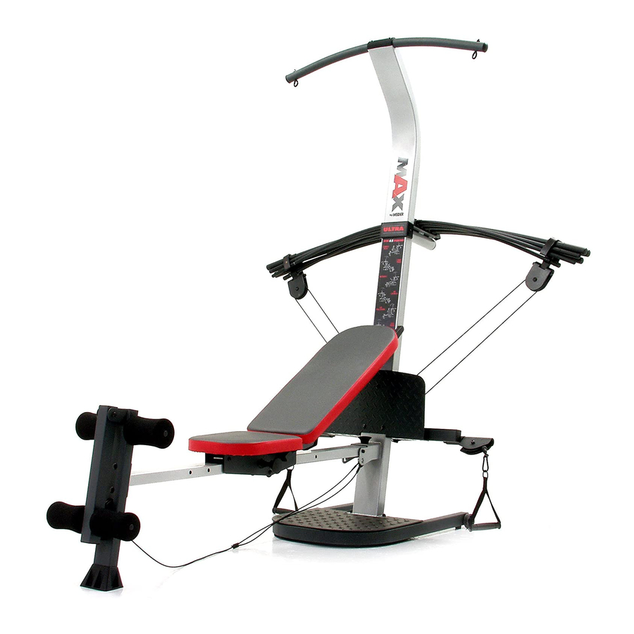
WEIGHT SYSTEM EXERCISER
User's Manual
Sears, Roebuck and Co., Hoffman
Estates, IL 60179
Advertisement

Related Manuals for Weider MAX XP400


Summary of Contents for Weider MAX XP400
- Page 1 Model No. 831.15392.2 Serial No. Write the serial number in the space above for reference, Serial Number Decal (under seat) WEIGHT SYSTEM EXERCISER o Assembly Adjustments User's Manual Part List and Drawing ,&CAUTION Read all precautions and instruc- tions in this manual before using this equipment.
-
Page 2: Table Of Contents
TABLE OF CONTENTS WARNING DECAL PLACEMENT ............. IMPORTANT PRECAUTIONS ..............BEFORE YOU BEGIN ..............ASSEMBLY ................ADJUSTMENTS ................CABLE DIAGRAM ................. EXERCISE GUIDELINES ..............ORDERING REPLACEMENT PARTS ..........Back Cover FULL ONE-YEAR WARRANTY ............Back Cover Note: A PART IDENTIFICATION CHART and a PART LIST/EXPLODED DRAWING are attached in the center of this manual. -
Page 3: Important Precautions
iMPORTANT PRECAUTIONS kWARNi NG: Toreduce ofserious the r isk read the injury, f ollowing important precautions before using the resistance system. Read all instructions in this manual before 12. Pull on the low pulley cable only while sitting using the resistance system. -
Page 4: Before You Begin
BEFORE YOU BEGIN Thank you for selecting the innovative MAX by WEl- after reading this manual, call 1-800-4-MY-HOME _ DER 'MXP400 resistance system. The resistance system (1-800-469-4663). To help us assist you, please note offers a selection of stations designed to develop every the product model number and serial number before major muscle group of the body. -
Page 5: Assembly
ASSEMBLY • Tighten all parts as you assemble them, unless Make Things Easier for Yourself instructed to do otherwise. This manual is designed to ensure that the resist- , As you assemble the resistance system, make ance system can be assembled successfully by sure all parts are oriented as shown in the draw- most people. - Page 6 Attach a Wheel (31) to the outside of the Base (1) with an M10 x 78mm Bolt (81), three M10 Washers (75), and an M10 Nylon Locknut (76). Do not overtighten the Locknut; the Wheel must be able to turn easily. Attach the other Wheel (not shown) in the same manner.
- Page 7 Attach the Lat Tower (4) to the Upright (3) with four M10 x 25mm Button Head Screws (87), and four M10 Lock Washers (68). Attach the Name Plate (89) to the Lat Tower (4) with two M4 x 16mm Screws (62). )"...
- Page 8 Attach two 8mm Metal Spacers (91), a 60mm Metal Spacer (39), and two Bearing Wheels (46) to one end of the Seat Carriage (12) with an M8 x 104mm Button Head Bolt (60) and an M8 Nylon second Locknut (65) as shown. Make sure that the parts set of wheels are oriented as shown in the inset drawing;...
- Page 9 12. Attach a Plastic Foot (53) to the Backrest Frame (15) with an M4 x 16mm Screw (62). Attach the two Guard Plates (17) to the inside of the Backrest Frame (15) with four M4 x 16mm Screws (62), 13. Orient the Backrest (14) as shown. Attach the Backrest to the Backrest Frame (15) with four 1/4"...
- Page 10 15. Locate the fulcrum on the Lat Tower (4) (see the inset drawing). Slide the Tray (35) onto the rods on the fulcrum. Make sure the Tray is oriented as shown in the drawing. Edges Set the Resistance Bars into the Tray (35) in the following order: the 10-pound Resistance Bar (67), the 20-pound Resistance Bar (36), an 80-pound Resistance Bar (95), the 10-pound Center...
- Page 11 19. Wrap the Long Cable (80) under a 90mm Pulley (28) as shown. Attach the Pulley and a Cable Trap (29) to the Upright (3) with an M10 x 120mm Button Head Bolt (40) and an M10 Nylon Locknut (76). Make sure the Cable Trap is oriented hold the Cable in the groove of the Pulley.
- Page 12 Locate the Leg Lever Cable (32), which has two ends that are the same length and a third end that is longer. Route the longest end of the Leg Lever Cable (32) through the hole in the Front Leg (6), and attach it inside of the hole in the Leg Lever (7) with an M10 x 50mm Bolt (63) and an M10 Nylon Locknut (76).
-
Page 13: Adjustments
ADJUSTMENTS This section explains how to adjust the resistance system. See the EXERCISE GUIDELINES on page 17 for important information about how to get the most benefit from your exercise program. Also, see the accompany- ing exercise guide to see the correct form for each exercise. Make sure all parts are properly tightened each time the resistance system is used. - Page 14 ATTACHING THE ACCESSORIES To attach a Handle (49) to a high pulley, first attach the high pulley to the resistance system (see ATTACHING THE HIGH PULLEYS AND LEG LEVER on page 13). Then, attach the Handle to the Short Cable (33) with a Cable Clip (51).
- Page 15 ADJUSTING THE BACKREST The Backrest (14) can be used in a level position or one of three inclined positions. To use the Backrest in a level position, secure the Seat Carriage (12) to the adjustment hole in the Bench Rail (5) next to the Front Leg (6) (see ADJUSTING THE SEAT on page 13).
-
Page 16: Cable Diagram
CABLE DIAGRAM The cable diagram shows the proper routing of the Long Cable (80). Use the diagram to make sure that Long Cable (80) the Cable has been assembled correctly. If the Cable has not been correctly routed, the resistance system will not function properly and damage may occur. -
Page 17: Exercise Guidelines
EXERCISE GUiDELiNES THE FOUR BASIC TYPES OF WORKOUTS PERSONALIZING YOUR EXERCISE PROGRAM Muscle Building Determining the exact length of time for each workout, To increase the size and strength of your muscles, as well as the number of repetitions or sets completed, push them close to their maximum capacity. - Page 18 Rest for a short period of time after each set. The slowly as you stretch and do not bounce. Ease into ideal resting periods are: each stretch gradually and go only as far as you can - Rest for three minutes after each set for a muscle without strain.
- Page 19 EXERCISE RESISTANCE SETS REPS MONDAY Date: AEROBIC EXERCISE TUESDAY Date: WEDNESDAY EXERCISE RESISTANCE SETS REPS Date: AEROBIC EXERCISE THURSDAY Date: FRIDAY EXERCISE RESISTANCE SETS REPS Date: Make photocopies of this page for scheduling and recording your workouts.
- Page 20 PART iDENTiFiCATiON CHART See the drawings below to identify small parts used in assembly. The number in parentheses below each draw- ing is the key number of the part, from the PART LIST on the reverse side of this page. Note: Some small parts may have been pre=attached.
- Page 21 MIO x 65mmButtonHeadScrew(70) MIO x 68mmBolt(56) MIO x 66mmCarriageBolt(83_ M10x 72mmBolt(64) MIO x 78mmBolt (81) MIO x 91mmBolt (90) MIO x 103mmBolt(66) M8 x 104mm Button Head Bolt (60) MIO x 102ram Button Head Bolt (24) M8 x 114ram Axle (57) MIO x 120mm Button Head Bolt (40) MIO x 140mm Carriage Bolt (73_...
- Page 22 PART LiST--Model No. 831.15392.2 R1005A Key No. Qty. Description Key No. Qty. Description Base 26mm Spacer Base Plate Plastic Foot Upright 25mm Square Inner Cap Lat Tower Leg Lever Bumper Bench Rail M10 x 68mm Bolt M8 x 114mm Axle Front Leg 1/4"...
- Page 23 EXPLODED DRAWING--Model No. 831.15392.2 m00SA 87 84 56---< 62 83 l...
-
Page 24: Full One-Year Warranty
Your Home For repair - in your home - of all major brand appliances, lawn and garden equipment, or heating and cooling systems, no matter who made it, no matter who sold it! For the replacement parts, accessories, and user's manuals that you need to do-it-yourself. For Sears professional installation of home appliances and items like garage...
Need help?
Do you have a question about the MAX XP400 and is the answer not in the manual?
Questions and answers
How long are the short cables?