Toro TimeCutter Z380 Operator's Manual
Hide thumbs
Also See for TimeCutter Z380:
- User manual (188 pages) ,
- Service manual (72 pages) ,
- Operator's manual (44 pages)

Related Manuals for Toro TimeCutter Z380


Summary of Contents for Toro TimeCutter Z380
- Page 1 Form 3354-516 Rev A Count on it. TimeCutter ®Z380 and Z420 Riding Mowers Model No. 74301--Serial No. 260000001 and Up Model No. 74327--Serial No. 260000001 and Up G000558 Register your product at www.Toro.com Original Instructions (EN)
-
Page 2: Ices
You are responsible for operating the product properly Contents and safel> You may contact Toro directly at xw, w , v Toro.com Introduction ............for product and accessory information, help Safety .............. -
Page 3: Table Of Contents
Storage .............. Operation ............Think SafeB T First ......Cleaning and Storage ......Recommended Gasoline ....Troubleshooting ..........Schematics ............Chec_ng the Engine Oil Level ... 14 Starting and Stopping Engine ......Operating the Blades ......The Safety Interlock System ....16 Driving Fonvard or Backward .... -
Page 4: Practices
Safety • Do not operate the mower without either entire grass catcher or the guard in place. • Be alert, slow down and use caution when This machine meets or exceeds the B71.1-2003 ma_ng turns. Look behind and to the side specifications of the American National... - Page 5 • Reduce speed anduseextremecautionon another ride and be run over or backed over slopes. by the mower. • Do not makesuddenturns or rapid speed Never allow children to operate the machine. changes. Use extra care when approaching blind corners, • Usea walkbehindmowerand/or a hand shrubs, trees, the end of a fence or other trimmerneardrop-offs,ditches, s teepbanks objects that may obscure vision.
- Page 6 • Check for proper brake operation frequentl> Adjust and service as required. • Maintain or replace safety and instruction decals as necessar> Use only genuine Toro replacement parts to ensure that original standards are maintained. Toro Riding Mower Safety The following list contains safeff information...
- Page 7 Fold along appropriate line sLOPE THIS IS A 5° SLOPE Example: Compare slope with folded edge.
-
Page 8: Decals
Safety and Instructional Decals Safety decals and instructions are easily visible to the operator and are located near any area of potential danger. Replace any decal that is damaged or lost. 93-6677 Warning--don't operate the mower with the deflector up or removed;... - Page 9 108-6109 To push the machine, move tow levers forward and then out to lock them into position. 105-7015 106-8717 Read the instructions before servicing or performing maintenance. Check tire pressure every 25 operating hours. Grease every 25 operating hours. Engine 108-2392 106-8742 Parking...
- Page 10 Battery Symbols Some or all of these symbols are on your battery Explosion hazard Keep bystanders a safe distance from the battery. No fire, open flame, or Wear protection; smoking. explosive gases can cause blindness and other injuries Caustic liquid/chemical Battery acid can cause...
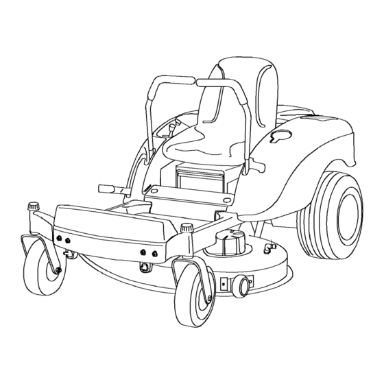
- Page 11 Product Overview G000557 Figure 3 Seat Height of cut lever Front caster wheel Anti-scalp roller Control levers Mower deck Rear drive wheel Control panel Footrest Cup holder Controls Become familiar with all of the controls Figure 5 and Figure 4 before you start the engine and operate the machine.
- Page 12 G000511 Figure Ignition switch Blade control switch (power take-off) Throttle/Choke Parking Brake The paring brake is automatically set when motion control levers are in the brake position. Always position the motion control levers into the brake position when you stop the machine or leave it unattended.
-
Page 13: Operation
Recommended Gasoline Operation Use UNLEADED Regular Gasoline suitable Note: Determine the left and right sides of the for automotive use (87 pump octane minimum). machine from the normal operating position. Leaded regular gasoline may be used if unleaded regular is not available. Think Safety First Important:... -
Page 14: Chec_Ng The Engine Oil Level
• Cleans the engine while it runs • Eliminates gum-like varnish buildup in the fuel In certain conditions during fueling, static system, which causes hard starting electricity can be released causing a spark Important: Do not use fuel additives which can ignite the gasoline vapors. -
Page 15: Operating The Blades
Stopping Engine 1. Move the throttle lever to Fast (Figure Disengage the blades by moving the blade control switch to Off (Figure Turn the iguition key to Off (Figure Figure 7 Pull the wire off of the spark plug(s) to prevent Blade control switch--On Blade control... -
Page 16: The Safety Interlock System
The Safety Interlock System control switch, and rise slightly from the seat; the engine should stop. While sitting on the seat, move the blade control switch to Off, and lock the motion If safety interlock switches are disconnected control levers in neutral. Start the engine. -
Page 17: Stopping The Machine
Children or bystanders be injured i /4 they move or attempt to operate the mower while it is unattended. Always remove the ignition key and move motion control levers to the brake position when leaving the machine unattended, even if just for a few minutes. Adjusting the Height of Cut... -
Page 18: Adjusting The Motion Control Levers
Important: Make sure that the spacers stay in place when loosening the knobs to move the seat. Loss of the spacers result in damage to the seat. Move the seat to the desired position tighten the _obs. G000520 Figure Control lever Control arm shaft Bolt... -
Page 19: Adjusting The Footrest
Side Discharge The mower has a hinged grass deflector that disperses clippings to the side and down toward the turf. Without the grass deflector, discharge cover, or complete grass catcher assembly mounted in place, others exposed to blade contact and thrown debris. - Page 20 If a blade is at Correct Intervals damaged or worn, replace it immediately with a genuine Toro replacement blade. Normal13; mow every four days. But remember, grass grows at different rates at different times.
-
Page 21: Maintenance
Maintenance Note: Determine the left and right sides of the machine from the normal operating position. Recommended Maintenance Schedule(s) Maintenance Service Maintenance Procedure Interval After the first 5 operating • Change the engine oil. hours • Check the safety interlock system. -
Page 22: Premaintenance Procedures
Premaintenance Grease the front caster pivots and wheels (Figure 19). Procedures 1. Park the machine on a level surface and disengage the blade control switch. Removing Installing Move the motion control levers to the brake Engine Hood position, stop the engine, remove the ke3, and wait for all moving parts to stop before leaving 1. -
Page 23: Engine Maintenance
Engine Maintenance Servicing the Air Cleaner Foam Element: Clean after every 25 operating hours, or yearl?, whichever occurs first. Paper Element: Replace after every 100 operating hours or yearly whichever occurs first. Note: Service the air cleaner more frequently (every few hours) if operating conditions extremely dusty or sand>... -
Page 24: Servicing The Engine Oil
Servicing the Engine Oil Check the oil level daily or after every 8 hours. Change the oil after the first 5 operating hours every ._( operating hours thereafter. Oil _;pe: Detergent oil (API service SF, SG, SH, SJ, or higher) Crankcase Capacity: G000527 •... -
Page 25: Servicing The Spark Plug
5. Slide the drain hose over the drain valve. 6. Place a pan below the drain hose• Rotate oil drain valve to allow oil to drain (Figure 26)• G000536 Figure 27 Oil filter Adapter Gasket Install the replacement oil filter to the filter Figure 26 adapter•... -
Page 26: Fuel System Maintenance
2. Tighten the spark plug to 30 ft-lb (41 N-m). 3. Push the wire onto the spark plug (Figure 28). Fuel System Maintenance Draining the Fuel Tank G001772 In certain conditions, gasoline is extremely Figure 28 flammable and highly explosive. A fire or explosion from... -
Page 27: Replacing The Fuel Filter
Electrical System Maintenance CALIFORNIA Proposition 65 Warning Battery posts, terminals, related accessories contain lead lead compounds, chemicals known to the State California to cause cancer and reproductive G000534 harm. Wash hands after handling. Figure 30 Filter Hose clamp Charging the Battery Fuel line Removing the Battery... -
Page 28: Servicing The Fuses
Incorrect battery cable routing could damage the machine and cables causing sparks. Sparks cause the battery gasses to explode, resulting in personal injury. Always disconnect the negative (black) battery cable before G000538 disconnecting the positive (red) Figure cable. Positive battery post Red (+) charger lead •... -
Page 29: Drive System Maintenance
Check the cutter blades daily for sharpness, and for aW wear or damage. File down aW nicks and sharpen the blades as necessar> If a blade is damaged or worn, replace it immediately with a genuine Toro replacement blade. For convenient Figure 33 sharpening and replacement, you may want to keep extra blades on hand. - Page 30 To ensure optimum performance level surface to the cutting edge, position A, of continued safer) Tconformance of the machine, use the blades (Figure 36). Note this dimension. genuine Toro replacement blades. Replacement blades made by other manufacturers may result in G000619 non-conformance with safety standards.
-
Page 31: Leveling The Mower From
Check the air pressure of all four tires• If needed, adjust to the recommended inflation; refer to Chec_ng the Tire Pressure in Drive System Maintenance, page 29. G000552 Set the height-of-cut lever to position D Figure 38 [3 inch (76 mm)]. Sharpen at original angle Carefully rotate the blade(s) side to side (Figure 40). -
Page 32: Adjusting The Front-To-Rear Blade Slope
refer to Chec_ng the Tire Pressure in Drive System Maintenance, page 29. Check and adjust the side-to-side blade level &a if you have not checked the setting; refer to Leveling the Mower from Side-to-Side• Measure the length of the rod extending out of the adjusting block on the sides of the chassis (Figure 43). -
Page 33: Removing The Mower
level of the mower; refer to Leveling the G000545 Mower from Side-to-Side• Removing the Mower Note: Before removing the mower, make a note for which holes are used in the leveling brackets (Figure 47)• Park the machine on a level surface and disengage the blade control switch. -
Page 34: Replacing Mower Belt
Q000548 Figure 38 inch leveler bracket shown 1. Leveling bracket 3. Adjusting rod 2. Hairpin cotter and washer Slide the mower rearward to remove mower belt from the engine pulle 7 Slide the mower out from underneath machine. G000B40 Figure 48 Note: Retain all parts for future installation. -
Page 35: Replacing The Grass Deflector
wait for all moving parts to stop before leaving Slide rod through second grass deflector the operating position. bracket and internal lock washer (Figure 49). Slide the mower under the machine. Insert rod at front of grass deflector into short stand-off on deck•... - Page 36 Q000555 Figure 50 Hose Washout fitting Coupling Lower the mower to the lowest height-of-cut. Sit on the seat and start the engine. Engage blade control switch and let the mower run for one to three minutes. Disengage the blade control switch, stop the engine, and remove the ignition ke 7 Wait for all moving parts to stop.
-
Page 37: Storage
Storage Stop the engine, allow it to cool, and drain the fuel tank; refer to Draining the Fuel Tank in Fuel System Maintenance, page 26. Cleaning Storage Restart the engine and run it until it stops. 1. Disengage the blade control switch, set the Choke or prime the engine. - Page 38 Troubleshooting Problem Possible Cause Corrective Action The engine overheats. engine load Reduce ground speed. excessive. oil level in the Add oil to the crankcase. crankcase is low. Remove the obstruction The cooling fins air passages under from the cooling fins and engine blower housing...
- Page 39 Problem Possible Cause Corrective Action Fill the fuel tank• The engine will start, The fuel tank is empty• • • starts hard, or fails to keep The fuel valve turned off. Open the fuel valve• running• The choke is not on. Move the choke lever...
- Page 40 Problem Possible Cause Corrective Action There is abnormal vibration. The engine mounting Tighten engine bolts are loose. mounting bolts. The engine pulley, idler Tighten the appropriate pulley, or blade pulley pulley. loose. Contact an Authorized The engine pulley Service Dealer. damaged.
-
Page 41: Schematics
Schematics (IGNITION) WIRE COLOR CODES i xi I'BK'4 BLACK I'pK4 PINK I'BN'Im BROWN I'R"lm m-BU"_ BLUE I'T'I" I-GN"In GREEN I'VlO_ VIOLET m-Gy'4 GREY _'VW WHITE m'OR4 ORANGE _-y4 YELLOW (PTO) .Ba.i_o I_1_i FUEL SOLENOID MAGNETO SHOWN OFF POSITION (BRAKE) MODELS: SHOWN WITH 74301 (SEAT) - Page 42 Manufacturer's Warranty Coverage: This evaporative emission control system is warranted for two years. If any evaporative emission-related part on your equipment defective, the part will be repaired or replaced by The Toro ®Company. Owner's Warranty Responsibilities: • As the equipment...
-
Page 43: Lyndale Avenue South Bloomington, Mn
Covered If for any reason you are dissatisfied with the Service Dealer's analysis or with the assistance provided, contact us at: The Toro Company and its affiliate, Toro Warranty Company, pursuant to an agreement between them, jointly promise to Customer Care Department,...
Need help?
Do you have a question about the TimeCutter Z380 and is the answer not in the manual?
Questions and answers