EverFocus ECOR Series Instruction Manual
Hide thumbs
Also See for ECOR Series:
- Instruction manual (105 pages) ,
- Instruction manual (104 pages) ,
- Instruction manual (23 pages)
Table of Contents
Advertisement
Advertisement
Table of Contents

Related Manuals for EverFocus ECOR Series


Summary of Contents for EverFocus ECOR Series
- Page 1 Instruction Manual...
- Page 2 All rights reserved. No part of the contents of this manual may be reproduced or transmitted in any form or by any means without written permission of the Everfocus Electronics Corporation. Release Date: May 2009 Windows is a registered trademark of the Microsoft Corporation.
- Page 3 Safety Precautions • To avoid any damage, please consider the following safety warnings: • Never place the recorder near to heaters, furnaces, other heat sources or under direct solar irradiation. • Operate the device only in locations providing the tolerable operating temperature range 0°C~40°C/32°F ~ +104°F.
- Page 4 WEEE This Product is RoHS compliant. The information in this manual was current upon publication. The manufacturer reserves the right to revise and improve his products. Therefore, all specifications are subject to change without prior notice. Misprints reserved. Please read this manual carefully before installing and using this unit. Be sure to keep it handy for later reference.
-
Page 5: Table Of Contents
TABLE OF CONTENTS PRODUCT OVERVIEW ..................... 1 ........................... 1 EATURES ......................2 ACKAGE ONTENTS ........................3 PECIFICATIONS ........................5 RONT ANEL ........................7 ANEL INSTALLATION........................9 ......................9 IDEO ONNECTIONS .................. 9 UDIO ONNECTION NSTALLATION ................10 LARM NPUT UTPUT NSTALLATION .................... - Page 6 4.5.1 Layout Change ............................. 23 4.5.2 Bring to Full Screen Mode ........................23 ........................24 UICK 4.6.1 Triplex Operation ..........................24 4.6.2 Change Camera Order ......................... 24 ..........................25 4.7.1 Standard Copy ............................25 4.7.2 Quick Copy ............................26 ..........................26 EARCH 4.8.1 Time Search ............................
- Page 7 EMOTE PTZ C ....................83 EMOTE ONTROL ......................84 EMOTE LAYBACK EVERFOCUS DDNS SETUP .................... 85 LINKSYS & D-LINK PORT FORWARDING ............... 86 ................... 86 INKSYS ORWARDING ..................... 88 ORWARDING TROUBLESHOOTING ....................91 APPENDIX A: TIMING OF ALARM MODES..............92...
-
Page 8: Product Overview
Pentaplex Operation (Simultaneously live, recording, playback, archive, and remote viewing) User friendly GUI with graphical icons and visual indicators Multiple Control Inputs: mouse/front panel/remote control/EKB500 Free EverFocus DDNS service Remote configuration support from built-in web interface Smart Motion Search function... -
Page 9: Package Contents
1.2 Package Contents Digital Video Recorder x1 User’s Manual x1 AC Adapter and Power Cord x1 Handheld Remote Control (batteries included) x 1 Hard Drive Rack Mount x1 * SATA Connection Cable x1 * Pack of screws x 1 * * marked accessories not included in some models... -
Page 10: Specifications
1.3 Specifications Video Format NTSC / PAL (auto detected by system) Operating System Embedded Linux ECOR4: 4 x 1 V FBAS, BNC, 75 Ohm Video Input ECOR8: 8 x 1 V FBAS, BNC, 75 Ohm Main monitor: 1 V FBAS, BNC at 75 Ohm Video Output 1 x VGA ( res. - Page 11 Playback Search Function By time / date; by event (alarm / motion); Smart Motion Grid Search Adjustable by channel , 22x15 sensor fields each with 10 levels Motion Detection sensitivity Video Loss Detection Event Log Up to 10000 events Event Alarm Fan failure, hard disk failure, hard disk temperature over, hard disk full Setup Graphical On-Screen-Display...
-
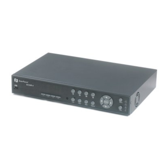
Page 12: Front Panel
1.4 Front Panel Your primary interaction with your new DVR will be through the Front Panel buttons and their corresponding buttons on the included Remote Control. Take a moment to learn where the keys are as the remainder of the manual will refer to them often. 1. - Page 13 6. SEQ Press this key to enter the auto sequential switching mode. The sequence dwell time can be set in “Display Setting” tab of the Menu. For more detail about SEQ, please see “5.8.2 Display Setting- Main M/T SEQ”. 7. Search Press this key to enter Search Menu.
-
Page 14: Back Panel
1.5 Back Panel During initial setup you will be connecting your DVR to multiple input and output devices. This is done through the back panel. 1. Power Plug the DC 12V power source into the power socket. 2. Alarm In Connect up to 4 / 8 alarm inputs, selectable between dry contact or TTL/CMOS signal polarity. - Page 15 7. Video In Connect camera’s video output or other composite video source to the video input connection. 8. Video Out Connect a CCTV monitor to the video output connection. 9. VGA Connect a VGA monitor to the VGA output connection. 10.
-
Page 16: Installation
Chapter 2 Installation 2.1 Video Connections Camera and CCTV monitor must use 75 Ohm video cable (e.g. RG-59, RG-6, RG-11) with BNC connectors. Due to inappropriate absorbability, 50 Ohm coax cable (e.g. RG-58), antenna cable and other types of coaxial cable are not compatible. All connected video sources must provide a 1 Vpp NTSC or PAL standard video signal. -
Page 17: Alarm Input / Output Installation
2.3 Alarm Input / Output Installation ECOR DVR provides 4 / 8 alarm inputs. Inputs have to be switched through dry contacts. The output relays provide a dry N.O. / N.C. contact.. All settings are programmed in the ALARM menu. Pin assignment: Group PIN label... -
Page 18: Network Connection
2.4 Network Connection ECOR DVR provides fast MPEG-4 format image transmission and network remote configuration. ATTENTION: A monitor is required for initial network configuration. For more information about network setup, please refer to Chapter 7. Physically, two basic types of connection are possible: 2.4.1 Direct PC Connection through Crossover Network Cable Figure 2.1 The point-to-point connection of DVR and PC requires a crossover (crossed) network cable. -
Page 19: Network System Requirements
Speed dome or pan/tilt/zoom control is available through web browser if the DVR is connected to a network. Local control is provided by the optional EKB 500 keyboard. Supported protocols: EverFocus, Pelco-D, Pelco-P, Transparent, Samsung. Termination Resistor ON at last dome Figure 2.3... -
Page 20: Final Install Process
2.6 Final Install Process Once you have completed the basic wiring connections, you are ready to turn on the DVR. Simply plug in the power source. The POWER LED will light up if power is normal. Once the system has finished loading, you can begin to set up the menu options for the DVR. -
Page 21: Mouse And Front Panel Operation
Chapter 3 Mouse and Front Panel Operation ECOR series DVR supports multiple sources to control the DVR. It can be controlled with a mouse, the front panel, an EKB500, the handheld remote control, or serial command from RS232 port. This chapter will cover the basic operation using mouse and front panel. 3.1 General USB Mouse Operation 3.1.1 OSD Root Menu 1. -
Page 22: Operation In Configuration Menu
3.1.2 Operation in Configuration Menu The Main menu (shown in Figure 3.2) is divided into 3 main sections. Figure 3.2 (OSD Menu) 1 In section 1, there are twelve setup options available. Move the mouse over an icon to select it. 2 In section 2, the main options for the selected icon will be displayed. - Page 23 Check box: Click on the box to check or uncheck it. Checked will enable the function, unchecked will disable the function. Button: Click the button to execute the function. Selection box: Click Up/Down arrow to increase or decrease the value. Bar: Click and hold on the bar to adjust the cursor Left or Right.
-
Page 24: General Front Panel Operation
3.2 General Front Panel Operation 3.2.1 Front Panel Key Review The basic principle of front panel operation is to use navigation keys (up, down, left and right) to navigate among the menu items. Use “Enter” key to confirm a selection or enter the next level menu. Press “Menu” key to enter the Main Menu or exit from the current level of the menu. -
Page 25: Component Options
3 In section 3, all the details for the selected option will be available here. Use the arrow keys to move between items and press “Enter” to make changes. Note: press “Menu” button to go back to the previous menu section. 3.2.3 Component Options Textbox: Press Enter key and an on-screen keyboard will appear below. -
Page 26: General Dvr Operations
Chapter 4 General DVR Operations This chapter introduces the operations on major functions including playback, layout change, sequence, triplex operations, archive, and search. 4.1 Record By default, the ECOR series DVR will always be in record mode. When the DVR is turned on, it will start to record. - Page 27 3. If an invalid user name or password is used 5 times, the DVR will give an error message and automatically lockdown. No access will be granted for 10 minutes without the backdoor password. To obtain the backdoor password, you will need to contact EverFocus Technical Support and give the provided access code.
-
Page 28: Playback Operation
4.3 Playback Operation 4.3.1 Playback Mouse: Right-click while viewing cameras to bring up menu bar and click to start playback. Front panel: Press button while viewing cameras to directly start playback. 4.3.2 Reverse playback Mouse: Right-click while viewing cameras to bring up menu bar and click to start rewind. -
Page 29: Fast Backward
4.3.5 Fast backward Mouse: While in playback mode, right-click to bring up menu bar and click to start fast rewind. Click the button again to increase speed to higher level (2x, 4x, 8x, 16x, 32x, or max). Front panel: While in playback mode, press key to start fast rewind. -
Page 30: Layout Change
4.5 Layout Change 4.5.1 Layout Change The 4 CH ECOR DVR has a total of three display modes available, and the 8 CH ECOR has four. The different available layouts are shown below: (9 screens) (4 screens) (PIP) (Full) To change layout, follow the steps below: By mouse: Right-click to bring up the menu bar and click to switch between 9, 4, PIP and full displays. -
Page 31: Quick Menu
4.6 Quick Menu In 9/4 displays mode, use arrow keys to move between select different screens. Press the “Enter” key while selecting a screen to bring up a small quick menu (see Figure 4.3). Note: This menu can only be accessed using the front panel. Figure 4.3 4.6.1 Triplex Operation Each camera can be individually set in either live mode or playback mode. -
Page 32: Copy
4.7 Copy To bring up Copy menu: to enter Copy Setup Menu. By mouse: Right-click to bring up the menu bar and click on By front panel: Press key to enter Copy Setup Menu. Figure 4.4 (Copy Menu – Standard Copy) 4.7.1 Standard Copy Camera: Select which cameras will be copied. -
Page 33: Quick Copy
4.7.2 Quick Copy Figure 4.5 (Copy Menu – Quick Copy) Select Auto Copy Logic: Copy Content: Select content to be copied. “Alarm only” will copy only Alarm events within the selected time. “All” will copy all video within the selected time. Copy Time From: Select how far back you wish to copy from the drop-down list. -
Page 34: Time Search
Figure 4.6 (Search Menu – Time Search) 4.8.1 Time Search Play From: Select the time period to be searched by choosing the Date and Time. Click on the “Search” button to start search. The DVR will automatically play the video being searched. 4.8.2 Event Search Figure 4.7 (Search Menu –... -
Page 35: Smart Motion Search
From: Select starting date and time To: Select ending date and time. Camera: Select which cameras to search for. Event: Select which event type(s) to search for. Choose from Alarm, Motion, Video Loss, or System Event. Click on the “Search” button to start searching. The search results will be shown as a list of events, explained in section 4.8.4. -
Page 36: Search Result
Figure 4.9 (Search Menu – Set Grid) Set Grid: Choose which areas of the motion grid will be included in the search. The areas you set in motion search must also be active in the motion settings of the Camera Setting Menu. Press “Edit” button to start editing motion grid. - Page 37 Figure 4.10 (Search Menu – Event List) : Go to the first page of event list. : Go to the previous page of event list. : Go to the next page of event list. : Go to the last page of event list. Click on any event to highlight it.
-
Page 38: Logout
4.9 Logout Figure 4.11 is a screen shot of the LOGOUT SETTING MENU. Figure 4.11 (Logout Menu) Press “Logout” button when you are ready to logout from the system. You will need to login again before accessing any other options. -
Page 39: Dvr Configuration
Chapter 5 DVR Configuration This chapter will walk you through the DVR Menu Settings step by step and show you how to set the DVR for your specific application. 5.1 OSD Setting Menu To bring up the Main Menu, right-click with the mouse to bring up the menu bar and click the button. -
Page 40: Play
Record Audio: Check the box to record audio. Resolution: Select recording resolution based on video format NTSC: 704x480 / 704x240 / 352x240 PAL: 704x576 / 704x288 / 352x288 Time Stamp: Select if the time and date will display while recording. Choose from Top, Bottom, or Off. Record Overwrite: Check the box and disk will begin overwriting when full. -
Page 41: Camera Setting
5.3 Camera Setting Figure 5.3 is a screen shot of the CAMERA SETTING MENU. This menu is used to configure individual camera settings. Figure 5.3 (Camera Menu-Basic Setting) 5.3.1 Basic Setting Camera: Select the camera number. Title: The title setting allows you to assign a title to each camera input. Each channel supports a title with up to 16 characters. - Page 42 Normal Speed: Record speed for continuous recording. The speed is limited to the maximum recording rate of the DVR (displayed in the bottom left corner) divided by the number of installed cameras. Event Speed: Record speed for event recording. Event record speed can be set from 1 to 30 (25 for PAL). PTZ ID: Set PTZ ID from 001~127 or OFF (OFF is the same as 000).
-
Page 43: Video Adjust
5.3.2 Video Adjust Figure 5.5 (Camera Menu – Video Adjust) Camera: Select the camera you wish to adjust. “Title” will change to the name of the selected camera. Brightness: Adjusts how bright/dark the picture appears. If details appear to be lost in the shadows or darker regions, try increasing the Brightness. -
Page 44: Motion
5.3.3 Motion Figure 5.6 (Camera Menu – Motion) Camera: Select the camera you wish to adjust. “Title” will change to the title name of the selected camera. Enable: Check box to enable motion detection. Other motion options will not be available unless this feature is selected. - Page 45 Set Grid: Press “Edit” button to start editing motion grid. Click and drag the mouse to select specific areas. Press “Set All” button to select the entire area. Press “Clear All” to clear all the grids selected. Press “Save & Back”...
-
Page 46: Video Loss
5.3.4 Video Loss Figure 5.8 (Camera Menu – Video Loss) Camera: Select the camera you wish to adjust, “Title” will change to the title name of the selected camera. Enable: Check box to enable Video Loss. Log: Check box to record video loss events in the log. Alarm Output: This will transmit a signal to another device. -
Page 47: Schedule Setting
5.4 Schedule Setting Figure 5.9 is a screen shot of the SCHEDULE SETTING MENU. In this menu you can set a unique timer to start recording during a specified time period. Figure 5.9 (Schedule Menu) First select one of the 10 available schedules from the left. Enable: Check the box to enable the scheduled time period. - Page 48 Figure 5.10 (Time Setup Menu) Normal: Constant IPS recording rate for the selected schedule. The maximum image rate is limited to the maximum recording rate (displayed in the bottom-left corner) divided by the number of active cameras. Event: IPS recording rate for events. Event record speed can be set from 1 to 30 IPS (25 for PAL). Record Mode: Choose whether the selected camera records Continuously or only during Events on the current schedule.
-
Page 49: Alarm & Event Setting
5.5 Alarm & Event Setting Figure 5.12 is a screen shot of the ALARM & EVENT SETTING MENU. This menu will walk you through alarm and event setup. Figure 5.12 (Alarm & Event Menu - Alarm) 5.5.1 Alarm Alarm: Select the alarm number. Enable: Check box to enable alarm. -
Page 50: Event
Output Type: Output action when alarm is triggered. Timeout: Alarm output lasts for the set time duration. Permanent: Alarm will continuously work until user presses Live key. Transparent: Alarm output keeps working according to the signal of alarm input. Trans+Timeout: Alarm output continues until event ends, then lasts for the set time duration. Timeout Dur: Timeout duration selectable from 1 to 150 seconds. - Page 51 Fan Failure: Figure 5.13 (Alarm & Event Menu – Event-Fan Failure) Log: Check box to record events in the log. Buzzer: Check box to enable buzzer when a fan fails to work. Alarm Output: This will transmit a signal to another device. It can be set to either “NONE” (not activated) or “1”...
- Page 52 HD Temperature: Figure 5.14 (Alarm & Event Menu – Event - HD Temperature) Log: Check box to record events in the log. Buzzer: Check box to enable buzzer when hard drive’s temperature is over the “Temp. Warning Limit”. Temp. Warning Limit: Sets the trigger temperature for all other active settings in HD Temperature. Choose from 55 C /131 F, 60 C /140 F, or 65 C /149 F.
- Page 53 HD Failure: Figure 5.15 (Alarm & Event Menu – Event - HD Failure) Log: Check box to record events in the log. Buzzer: Check box to enable buzzer when no hard drive is detected. Alarm Output: This will transmit a signal to another device. It can be set to either “NONE” (not activated) or “1”...
- Page 54 HD Full: Figure 5.16 (Alarm & Event Menu – Event - HD Full) Log: Check box to record events in the log. Buzzer: Check box to enable buzzer when hard drive is full. Alarm Output: This will transmit a signal to another device. It can be set to either “NONE” (not activated) or “1”...
-
Page 55: Network Setting
5.6 Network Setting Figure 5.17 is a screen shot of the NETWORK SETTING MENU. This menu is for setting up the configurations for networking to the DVR. There are 3 subentries in the NETWORK SETTING MENU: LAN, EMAIL and DDNS. Note: Since every Network Configuration is different, please check with your Network Administrator or ISP to see if your DVR requires specific IP addresses and/or port numbers. -
Page 56: Email
Gateway: This field shows the gateway for your network so the DVR will be recognized within the network. If DHCP or PPPoE is selected, this value will be assigned automatically. DNS Server 1: This field shows the primary DNS server for your network. When DHCP is selected and an internet connection is available, this value will be assigned automatically. -
Page 57: Ddns
DVR Name: Name you wish to use for the DVR (EverfocusDDNS only). Click on “Submit/Update” to update the chosen name on the server (EverfocusDDNS only). Note: For more details on DDNS setup, please see “Chapter 7 - Everfocus DDNS Setup”. -
Page 58: Disk Setting
5.7 Disk Setting Figure 5.20 is a screen shot of the DISK SETTING MENU. This menu will walk you through disk settings. Figure 5.20 (Disk Menu) Disk: Select the disk number. Disk Temperature: Indicates current disk temperature. Health Status: Indicates current health status of the disk. Disk Size/Total: Shows total disk size available. -
Page 59: Display Setting
5.8 Display Setting Figure 5.21 is a screen shot of the DISPLAY SETTING MENU. This menu will walk you through Monitor On-Screen Display (OSD) and Main Monitor Sequential setup. Figure 5.21 (Display Menu – Monitor OSD) 5.8.1 Monitor OSD These are the display options for the Main Monitor. Camera Title: Check the box to display camera titles. -
Page 60: Main M/T Seq
5.8.2 Main M/T SEQ This menu is used to setup the sequence order and dwell time on the main monitor. Figure 5.22 (Display Menu – Main M/T SEQ) Step: Sequence order. Cannot be changed. Camera: Select camera number that appears on the current step. Dwell (sec): Set the dwell time for each step. -
Page 61: System Setting
5.9 System Setting Figure 5.23 is a screen shot of the SYSTEM SETTING MENU. This menu is for setting up the system configurations of the DVR. There are 6 subentries in the SYSTEM SETTING MENU: Date/Time, Daylight Saving, User, Security, I/O Control and Firmware & Misc. Figure 5.23 (System Menu –... -
Page 62: Daylight Saving
5.9.2 Daylight Saving Figure 5.24 (System Menu – Daylight Saving) Daylight Saving: Check the box to enable daylight saving time. Start Date: Set the start date of daylight saving time. Start Time (hh:mm): Set the time when daylight saving time begins. Set To (hh:mm): This is what the time will change to when daylight saving begins. -
Page 63: User
End Date: Set the end date of daylight saving time. End Time (hh:mm): Set the time when daylight saving time ends. 5.9.3 User Figure 5.25 (System Menu – User) User List: Click on the drop-down to select a user from the list. The default choices are admin, user2, and user3. -
Page 64: Security
5.9.4 Security Figure 5.26 (System Menu – Security) Login Protect: Check the box to require user name and password when you enter configuration menu. Auto Logoff: Check the box to force the system to automatically log off if left unused for 2 minutes. This will also force the remote web viewer to automatically log off after 10 minutes. -
Page 65: I/O Control
Parity: This selects the level at which you will be connected. There are three options: None, Odd, or Even. RS485 PTZ Protocol: Select PTZ protocol from Transparent, Pelco D, Pelco P, Everfocus, or Samsung. 485 ID: If more than one DVR is used through the RS485 connection, this can be used to assign different ID numbers. -
Page 66: Firmware & Misc
5.9.6 Firmware & Misc. Figure 5.28 (System Menu – Firmware & Misc.) Firmware Current Firmware Version: Displays the current version. Firmware Upgrade: Press “Upgrade” button to upgrade the firmware. NOTE: To perform a Firmware Upgrade, you will need to connect a USB flash device with the latest version of the firmware Configurations Load Factory Default: Click this “Load”... -
Page 67: Information Setting
5.10 Information Setting Figure 5.29 is a screen shot of the INFORMATION SETTING MENU. This menu will walk you through the System and log setup. Figure 5.29 (Information Menu – System) 5.10.1 System System Version: Displays firmware version number. Model: Displays DVR model number. NTSC/PAL: Displays current video format. -
Page 68: Log
5.10.2 Log Figure 5.30 (Information Menu – Log) Log Type: Event: to see log sorted by event. User: to see log sorted by user. Operation: to see log sorted by operation. View Log: Press “View Log” button to view the log. See Figure 5.31 for more detail. Clear Log: Press “Clear Log”... - Page 69 Figure 5.31 (Log List) : Go to the first page of log. : Go to the previous page of log. : Go to the next page of log. : Go to the last page of log. Date/Time: Check the box to show log date/time. ID: Check the box to show detailed log information.
-
Page 70: Networking Overview
Chapter 6 Networking Overview This chapter will give you a basic instruction on how to set up the DVR for network connection. It is highly recommended that you have a working knowledge of what a network is and how it works. This will be helpful in completing the networking process. -
Page 71: Virtual Ports
There are many types of high speed Internet available. The most common ones are T1, Cable, and DSL (in order of speed). The DVR is not compatible with a dial-up connection. Note: EverFocus suggests having a minimum upload speed of 256KBps. This can be addressed by your Internet Service Provider. -
Page 72: What Is Your Network Setup
This makes it much simpler to host a website, email server, or other type of server connection. Everfocus suggests using a static IP address. If this is not available, you will need to use a dynamic IP address. This is explained below. -
Page 73: Simple One To One Connection
Once you have a cross-over cable plug one end into the LAN port on the back of the DVR and the other into the network card on the back of the computer. Log into the EverFocus DVR menu and go to the Network Setting Menu. You must use the Static IP option for this type of connection. - Page 74 Assign an IP of 192.168.001.003, a Subnet Mask of 255.255.255.000, and a Gateway of 192.168.001.001. You can ignore DNS Server. The next step is to set the computer’s network settings to match those of the DVR. You will need Administrator privileges on your Windows machine to do this. To assign a fixed IP address in Windows 2000/XP.
- Page 77 Click on the option that says “Use the following IP address” Assign an IP address of 192.168.1.2, a Subnet Mask of 255.255.255.0, and a Default Gateway of 192.168.1.1, then click OK. Restart both the computer and the DVR. To access the DVR from the computer, simply open Internet Explorer and in the address bar type: http://192.168.1.3...
-
Page 78: Direct High Speed Modem Connection
6.8 Direct High Speed Modem Connection Hi-speed modem Cat 5 Internet Straight Through Cable Straight Through Ethernet Cable Pin outs: The Figure below shows the pin configurations for a straight cable. Connection Procedure: The first step is to purchase or make a straight through cable. We recommend purchasing one if you have never made a straight through cable. - Page 79 Log into the EverFocus DVR menu and go to the Network Setting Menu. Input the Static IP address, the Subnet Mask, and the Gateway that you obtained from the internet service provider. Note: If you have a dynamic IP address, you can set the DVR to DHCP to automatically detect the network settings settings.
-
Page 80: Router Or Lan Connection
6.9 Router or LAN Connection Hi-speed modem Internet Cat 5 Straight Through Cable Router Straight Through Ethernet Cable Pin outs: The Figure below shows the pin configurations for a straight cable. Connection Procedure: The First step is to purchase or make a straight through cable. We recommend purchasing one if you have never made a straight through cable. - Page 81 Log into the EverFocus DVR menu and go to the Network Setting Menu. To let the router automatically assign an address: Set the Network Type to DHCP. Make sure to write down the IP address and the Gateway. Exit from the Menu to save settings.
- Page 82 To access the DVR from a computer simply open Internet Explorer and in the address bar type: http:// (IP address of the DVR) Note: The DVR’s IP address will only work at the location of the DVR. To connect from a different location over the Internet, see below.
-
Page 83: Remote Operation From Browser
Chapter 7 Remote Operation from Browser 7.1 Connecting to ECOR To access the DVR from a computer, open an Internet Explorer window and in the address bar type: Local connection: http:// (IP address from the DVR’s Network Menu) Internet connection: http:// (IP address given by your Internet Service Provider) The login page will appear on the screen similar to the one shown above. -
Page 84: Ie Browser Setting &Active Xc Ontrol Installation
7.2 IE Browser Setting & Active X Control Installation 7.2.1 Installing ActiveX controls When you first connect to the DVR’s IP address, you should see a screen like the one below. If you do not see a yellow bar like the one the arrow is pointing at, your security settings may be too high. If so, go to the section labeled “Enabling ActiveX Controls.”... - Page 85 Install the eDVR.cab file when prompted to do so. Once the file finishes installing, you will return to the same login page as before. Type in the username and password and click Login to view the cameras. Default username: admin Default password: 11111111...
-
Page 86: Enabling Activex Controls
7.2.2 Enabling ActiveX Controls Note: This section is only necessary if you DO NOT see the yellow ActiveX bar at the top of your browser screen when you first connect to the DVR. At the top of the Internet Explorer Window, click on Tools, then select Internet Options. Click the Security tab at the top of the window, then choose Custom Level near the bottom. - Page 87 In the Security Settings window, scroll to “ActiveX controls and plug-ins” Set the controls as follows: “Enable”: Allow previously unused ActiveX controls to run without prompt (Internet Explorer 7 only) Allow scriptlets (IE7 only) Automatic prompting for ActiveX controls Binary and script behaviors Display video and animation on a webpage that does not use external media player (IE7 only) Run ActiveX controls and plug-ins Script ActiveX controls marked safe for scripting...
- Page 88 Close the window so you are back at the login screen. Click the Refresh button to reload the page. Install the eDVR.cab file when prompted to do so. Once the file finishes installing, you will return to the same login page as before. Type in the user name and password and click Login to view the cameras.
-
Page 89: Remote Live View
7.3 Remote Live View 1. In the main page, you will see live images in a 4-screen display (or 9 screens, depending on the model). 2. The status of all cameras as represented by different colors in the top left corner. Green means normal; yellow means a motion/Vloss event is happening;... -
Page 90: Remote Ptz Control
7.4 Remote PTZ Control 1. Select the PTZ camera from drop-down menu. 2. Use Direction Arrows (up, down, left, right) to move the camera to the desired direction and angle. 3. In the Iris option, you can decrease by clicking C the amount of light or increase it by clicking O. 4. -
Page 91: Remote Playback
7.5 Remote Playback To playback the video, press “Search” button. Select from “Time Search”, “Event Search”, or “Motion Search”. For more details about Search setting, please refer to “4.8 Search Setting”. Select Camera Playback Control Play Status Playback Control Keys: Fast Reverse. -
Page 92: Everfocus Ddns Setup
Chapter 8 EverFocus DDNS Setup Setup Steps: Step 1. Set up the Network Menu according to the instructions detailed in the Networking chapter. (Make sure that DNS Server 1 is set correctly or DDNS will not work) Step 2. Go to the website http://everfocusddns.com... -
Page 93: Linksys & D-Link Port Forwarding
Chapter 9 Linksys & D-Link Port Forwarding 9.1 Linksys Port Forwarding This section will cover a few simple configurations for the Linksys router. This chapter is only to offer some help to the installer and end user. Please understand we DO NOT support this product and will not give tech support on it. - Page 94 Applications and Gaming allows you to set up public services on your network, such as web servers, ftp servers, e-mail servers, or other specialized Internet applications. (Some Internet applications may not require any forwarding) To forward a port, enter the information on each line for the criteria required. Descriptions of each criterion are described here.
-
Page 95: D-Link Port Forwarding
9.2 D-Link Port Forwarding This section will cover a few simple configurations for the D-Link router. This chapter is only to offer some help to the installer and end user. Please understand we DO NOT support this product and will not give tech support on it. - Page 96 Click Virtual Servers on the left to bring up the following screen. Virtual Servers allows users who are connecting remotely to access services on the router’s Local Network. The functions of each field are described below. Virtual Server - Select Enabled or Disabled Name - Enter the name referencing the virtual service Private IP - The IP address of the device running the local services.
- Page 97 When you have input all the information for a virtual server, click on Apply to add it to the list at the bottom or Cancel to clear all fields. Here is an example of the information for each service: Name Private IP Protocol Private Port...
-
Page 98: Troubleshooting
Chapter 10 Troubleshooting If you have problems with the system, run through the following checklist to see if you can solve the problem. The DVR will not go into record mode. Bring up the DVR’s Menu and check under the Camera Menu. Verify that all connected cameras are checked as “Installed”... -
Page 99: Appendix A: Timing Of Alarm Modes
Appendix Appendix A: Timing Of Alarm Modes Transparent Mode Input Event Alarm Duration Event = Reaction Duration of alarm input source (motion, contact, system events...) Event Resulting duration for this alarm mode, related to event record, alarm outputs, OSD message, reaction buzzer Timeout + Transparent Mode... - Page 100 Timeout Mode Input Event Alarm Duration Event Duration = Reaction Duration of alarm input source (motion, contact, system events...) Event Alarm duration for timeout, defined in the event setup menus Duration Resulting duration for this alarm mode, related to event record, alarm outputs, OSD message, reaction buzzer Permanent Mode...
- Page 101 Timeout Mode: Retrigger of Alarms Duration of alarm input source (motion, contact, system events...) Event Alarm duration for timeout, defined in the event setup menus Duration Resulting duration for this alarm mode, related to event record, alarm outputs, OSD message, reaction buzzer...
- Page 102 Timeout+Transparent Mode: Retrigger of Alarms Duration of alarm input source (motion, contact, system events...) Event Alarm duration for timeout, defined in the event setup menus Duration Resulting duration for this alarm mode, related to event record, alarm outputs, OSD message, reaction buzzer...
-
Page 103: Appendix B: Control Protocol
Appendix Appendix B: Control Protocol 1-1. PC to DVR Connection This Digital Video Recorder may be controlled by a computer using a 232-to-485 converter. Refer to the following picture to make the proper connections from your PC to the DVR. - Page 104 2-1. Packet Format: Commands should be sent in packets using the following command string: Length Byte Receiver ID high byte Receiver ID low byte Opcode Byte Data Byte Checksum Byte 2-2. Length Byte This Length Byte is a prefix. EX: 0x85 ==> this packet contains 5 bytes. (not including Length byte) 2-3.
- Page 105 2-4. Opcode Byte & Data bytes 2-4-1. OPcode 0x4B : A remote key pressed 2-4-2. Code functions for “Remote key pressed” 0x00 0x1c >>> 0x01 0x1d >>> 0x02 0x1e (reserve) 0x03 0x1f (reserve) 0x04 VIEW 0x20 0x05 ZOOM 0x21 0x06 0x22 0x07 MENU...
- Page 106 Checksum is found by taking the sum of all previous bytes (including the length byte) and using mask of 0x7f. For help with computing the Checksum Byte, use the EverFocus Checksum Calculator or Serial Comm programs, found at the following link: ftp://208.50.31.200/Checksum%20Calculator/...
- Page 107 Tel: +1-626-844-8888 Sales: +1-631-436-5070 Fax: +1-626-844-8838 Fax: +1-631-436-5027 Ihr EverFocus Produkt wurde Your EverFocus product is designed entwickelt und hergestellt mit qualitativ and manufactured with high quality hochwertigen Materialien und materials and components which can Komponenten, die recycelt und wieder be recycled and reused.
Need help?
Do you have a question about the ECOR Series and is the answer not in the manual?
Questions and answers