Table of Contents
Advertisement
Quick Links
Download this manual
See also:
Operator's Manual
Bimplicilq
MANUFACTURING,
INC.
0
Bimpliuilq
intermediate
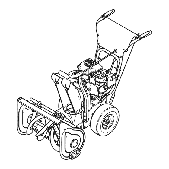
nowthrowers
This Dealer Setup Instruction covers the following products:
intermediate
Frame
Snowthrowers
Mfg. No.
1695302
1695311
1695410
1695313
1695314
1695411
Description
SM111924E, 9GT, B&S 24
SM111924EX, 9GT, B&S 24 (CE)
SM111924EX, 9GT, B&S 24 (CE)
SNP 11924E, 9GT, B&S 24
SNP 11924EX, 9GT, B&S 24 (CE)
SNP 11924EX, 9GT, B&S 24 (CE)
Briggs & Stratton Yard Power Products Group
Copyright © 2007 Briggs & Stratton Corporation
Milwaukee, WI USA. All Rights Reserved
Form No. 1735249
09/2007
TP 300-4681-01-IW-SN
Advertisement
Table of Contents

Summary of Contents for Simplicity 1695311
- Page 1 Bimplicilq MANUFACTURING, INC. Bimpliuilq intermediate nowthrowers This Dealer Setup Instruction covers the following products: intermediate Frame Snowthrowers Mfg. No. Description 1695302 SM111924E, 9GT, B&S 24 1695311 SM111924EX, 9GT, B&S 24 (CE) 1695410 SM111924EX, 9GT, B&S 24 (CE) 1695313 SNP 11924E, 9GT, B&S 24 1695314 SNP 11924EX, 9GT, B&S 24 (CE) 1695411...
- Page 2 intermediate Frame Snowthrowers SAFETY RULES Read these safety rules and follow them closely. Failure to obey these rules could result in loss of control of unit, severe personal injury or death to you, or bystanders, or damage to property or equipment. The triangle ,_ in text signifies important cautions or warnings which must be followed.
-
Page 3: Table Of Contents
intermediate Frame Snowthrowers Table of Contents Unpacking..........1. Uncrate..........2. CheckTire Pressure ........3. install Handles ..........4. Secure Dash ..........5. install Chute ..........6. install Chute Rotator Crank........7. Tube Handle Levers ........8. Auger Shaft Lubrication ........9. -
Page 4: Unpacking
intermediate Frame Snowthrowers Size 15 x 5.0-6 1,38 16 x 4.8-8 TP 300-4681-01 qW-SN 09/2007... -
Page 5: Install Handles
intermediate Frame Snowthrowers @@@@ 5/16-18 5/16-18 5/16-18 x 2-3/4 7 Nm 5 Ib-ft 09/2007 TP 300-4681-01 dW-SN... -
Page 6: Install Chute
intermediate Frame Snowthrowers 5/16-18 × 1-1/2 TP 300-4681-01 dW-SN 09/2007... -
Page 7: Tube Handle Levers
intermediate Frame Snowthrowers 09/2007 TP 300-4681-01-IW-SN... -
Page 8: Auger Shaft Shear Pins
intermediate Frame Snowthrowers TP 300-4681-01-IW-SN 09/2007... -
Page 9: Spout Rotator Lubrication
intermediate Frame Snowthrowers 09/2007 TP 300-4681-01 dW-SN... -
Page 10: Perform Safety Checks
intermediate Frame Snowthrowers Perform Safety Checks Check Engine Controls 1. Make sure all safety guards are in place and all nuts, bolts, clips, cotter pins and wires are secure. 2. Check to make sure spark plug wire is attached. 3. Check all controls for proper operation: a. -
Page 11: Checksnowthrower Controls
intermediate Frame Snowthrowers Perform Safety Checks Check Snowthrower Controls 1. Check the skid shoes to make sure they are set at the desired height. Adjust if necessary. 2. Check the traction drive control (B, Figure 2). Snowthrower motion should stop when the control is released. -
Page 12: Adjustments
intermediate Frame Snowthrowers ,WARNING Do not over-tighten, as this may lift the lever and cause auger drive to be engaged without depressing the Auger Control. 1 .With the drive lever released, the hook (B, Figure 3) should barely touch the lever (C) without raising it. There can be a maximum 1/32"... -
Page 13: Traction Drive Adjustment
intermediate Frame Snowthrowers WARNING Run-In Adjustment ALL MODELS Do not over-tighten, as this may cause traction 1. After 5 hours of use, check for proper adjustment. drive to engage without depressing the traction Readjust clutch cable if necessary by increasing ten- drive control (arm must remain in down position). -
Page 14: Scraper Bar & Skid Shoe Adjustment
intermediate Frame Snowthrowers 7. Loosen shift lever nuts (B, Figure 6), and position the shift speed lever (A) in the lowest forward speed. Scraper Bar & Skid Shoe Adjustment On smooth surfaces such as concrete or asphalt, the scraper bar should scrape the surface. On surfaces such as gravel, the scraper bar should be high enough so that it will not pick up gravel or debris. -
Page 15: Belt Adjustment
intermediate Frame Snowthrowers Belt Adjustment Auger Drive Belt If your snowthrower will not discharge snow, check the control cable adjustment. If it is correct, then check the condition of the auger drive belt. If it is damaged or loose,replace it (see Belt Replacement in this section of the manual). -
Page 16: Belt Replacement
intermediate Frame Snowthrowers Belt Replacement Auger Drive Belt The drive belts are of special construction and must be replaced with original factory replacement belts available from your nearest authorized service center. Some steps require the assistance of a second person. If the auger drive belt is damaged, the snow thrower will not discharge snow. - Page 17 intermediate Frame Snowthrowers Figure 14. Rotator Shaft Removal A. Pin, Hair B. Shaft Figure 16. Chute and Rotator Removal A. Chute and Rotator Figure 15. Offset Tube (Lower) Removal A. Nuts, KEPS, hex, 5/16-18 B. Bolts, Carriage, 5/16 x 1-1/2 C.
-
Page 18: Traction Drive Belt
intermediate Frame Snowthrowers Traction Drive Belt If the snow thrower will not move forward, check the trac- tion drive belt for wear or damage. If the traction drive belt is worn or damaged, replace the belt as follows. 1. Disconnect the spark plug wire. 2.


Need help?
Do you have a question about the 1695311 and is the answer not in the manual?
Questions and answers