Table of Contents
Advertisement
Safety Instructions
& Operator's Manual for
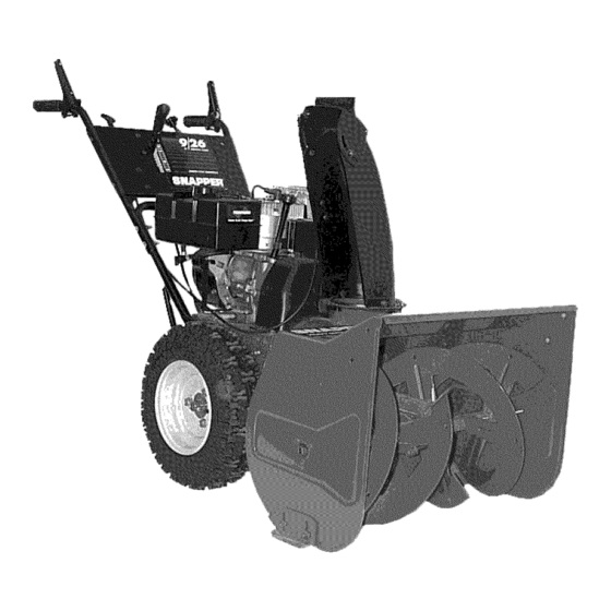
TWO STAGE
LARGE FRAME
SNOW THROWER
SERIES 6
MODELS
8246
9266
9266E
11306
I
MODEL
NUMBER
EXPLANATION
9
1261
6
I
E
I
ENGINE HP
AUGER WIDTH
ELECTRIC START
SERIES DESIGNATION
8 - 8.0 Engine HP (Engine Horse Power
9 - 9.0 Engine HP (Engine Horse Power)
11 - 11.0 Engine HP (Engine Horse Power)
24 - 24" Auger Width
26 - 26" Auger Width
30 - 30" Auger Width
6 - Series Designation
E - Electric Start
Thank you for buying a SNAPPER Product! Before operating your Snow Thrower, read this manual carefully and pay
particular attention to the "IMPORTANT
SAFETY INSTRUCTIONS"
on Pages 2 & 3. Remember that all power
equipment can be dangerous if used improperly. Also keep in mind that SAFETY requires careful use in accordance
with the operating instructions and common sense.
SNAPPERMcDonough,
GA., 30253
U.S.A.
COPYRIGHT
© 2003
SNAPPER
PRODUCTS
INC.
ALL RIGHTS RESERVED
MANUAL No. 7-5394 (I.R. 3/3/03)
Advertisement
Chapters
Table of Contents
Troubleshooting

Related Manuals for Snapper 9266


Summary of Contents for Snapper 9266
- Page 1 26 - 26" Auger Width 11 - 11.0 Engine HP (Engine Horse Power) 30 - 30" Auger Width Thank you for buying a SNAPPER Product! Before operating your Snow Thrower, read this manual carefully and pay particular attention to the "IMPORTANT SAFETY INSTRUCTIONS"...
- Page 2 If you have any questions pertaining to your snow thrower which your dealer cannot answer to your satisfaction, call or write the Customer Service Department at SNAPPER, McDonough, Georgia 30253. Phone: 800/935-2967. PROTECTION FOR CHILDREN...
- Page 3 Extinguish all cigarettes, cigars, pipes and other any new safety devices. sources of ignition. 10. Use only genuine SNAPPER replacement parts to Use only an approved fuel container. assure that original standards are maintained.
-
Page 4: Table Of Contents
Rubber Drive Tire Replacement ................TROUBLESHOOTING ................SERVICE SCHEDULE ................WARRANTY AND PRODUCT REGISTRATION ........ 20-21 IMPORTANT The figures and illustrations in this manual are provided for reference only and may differ from your specific model. Contact your Snapper dealer if you have questions. -
Page 5: Introduction
Section 2 - OPERATING INSTRUCTIONS INTRODUCTION Before starting machine, visually check location of all operational controls and identify major parts discussed in Operator's Manual. REMOTE DEFLECTOR CONTROL (26" & 30" MODELS) DISCHARGE CHUTE HIGH SPEED IMPELLER _CONTROL SPEED CONTROL LEVER --TRACTION CLUTCH BLOWERCLUTCH_... -
Page 6: Pre-Start Checklist
PRESS BOTH LEVERS --'1 Replace damaged cord immediately. Contact your RELEASE BLOWER Snapper service dealer for assistance. To reduce the CLUTCH LEVER; CONTINUE HOLDING risk of electric shock, use only with an extension WHEEL DRIVE cord intended for outdoor use having a cord type: SW-A, SOW-A, STW-A, STOW-A, SJW-A, SJTW-A SJTOW-A. - Page 7 Section 2 - OPERATING INSTRUCTIONS PRE-START CHECK LIST 2.1.9. Check the AC electrical outlet that will be used and make sure it is a polarized outlet. The machine has a polarized plug (one blade of plug is wider than the other) that will accept a polarized extension cord.
- Page 8 Section 2 - OPERATING INSTRUCTIONS STARTING, OPERATION & STOPPING AUGE_IMPELLER (RECOIL START MODELS) CONTROL (Continued From Previous Page) 2.2.2. PROPELLING SNOW THROWER oDL RIVE IMPORTANT: This snow thrower has six forward speeds and one reverse speed. 1. Move ground speed control to the desired speed position.
- Page 9 Replace damaged cord immediately. SPEED CONTROL TO"FAST" Contact your Snapper service dealer for assistance. To reduce the risk of electric shock, use only with MOVE INSERT KEY an extension cord intended for outdoor use having CHOKE TO a cord type: SW-A, SOW-A, STW-A, STOW-A, SJW- THE"ON"...
-
Page 10: Free Wheel Machine
Section 2 - OPERATING INSTRUCTIONS 2.2.12. FREE WHEEL MACHINE STARTING, OPERATION & STOPPING (ELECTRIC START MODELS) Snow Thrower can be transported without engine running and transmission drag. 1. Remove hair pins and clevis pins from both (Continue From Previous Page) wheel axles. - Page 11 SERVICE - AFTER FIRST 5 HOURS shots of grease from a grease gun into gear case. Snapper suggests using Benalene 900. The grease 3.2.1 CHECK AUGER DRIVE BELT plug for the gear case is located in front of the gear 1.
-
Page 12: Annually (End Of Season)
Section 3 - MAINTENANCE ANNUALLY (END OF EACH SEASON) Perform maintenance described maintenance schedule. 3.4.1. Engine owner's manual service Refer engine instructions. 3.4.2. Spark Plug owner's manual service Refer engine instructions. STORAGE PROCEDURE Refer to the Engine Owner's Manual directions regarding engine storage preparations. - Page 13 Section 4 - REPAIR & ADJUSTMENTS 4.1.2. AUGER BELT IDLER PULLEY WARNING ADJUSTMENT DO NOT attempt adjustments, maintenance, NOTE: To adjust the idler pulley and properly tension service, or repairs, with engine running. Stop auger. the auger belt, the auger control cable adjustment Stop engine.
- Page 14 Section 4 - REPAIR & ADJUSTMENTS 6. Tilt machine forward to gain access to drive system area. Secure machine in the tilted position DO NOT attempt adjustments, maintenance, to prevent tipping over. Remove drive system cover service, or repairs, with engine running. Stop auger. plate.
- Page 15 Section 4 - REPAIR & ADJUSTMENTS 6. Tilt machine forward to gain access to drive WARNING system area. Secure machine in the tilted position DO NOT attempt adjustments, maintenance, to prevent tipping over. Remove drive system cover service, or repairs, with engine running. Stop auger. plate.
-
Page 16: Skid Shoe Adjustment
Section 4 - REPAIR & ADJUSTMENTS 4.1.5. SKID SHOE ADJUSTMENT NOTE: It is recommended to raise the auger/impeller housing when clearing rough or graveled surfaces. To raise auger/impeller the skid shoes should be lowered. 1. Tilt machine up and place a wooden block under auger/impeller housing. -
Page 17: Single Handle Control Adjustment
Section 4 - REPAIR & ADJUSTMENTS 4.1.6. SINGLE HANDLE CONTROL ADJUSTMENT 2. Check position of the cam lock. It must align with the adjusting line located on the cam lock bracket. IMPORTANT: Standing in the operator's position, the left 3. To adjust, loosen the nuts on the cable guide handle bar lever is for wheel drive engagement support bracket and move the bracket in or out until... -
Page 18: Auger Shear Bolt Replacement
1. Remove shear bolt and nut from auger. Discard old shear bolt and nut. DO NOT reuse bolt or nut under any circumstances. Always replace existing hardware with genuine Snapper new replacement shear bolts and nuts. DO NOT substitute these CHUTE... -
Page 19: Troubleshooting
TROUBLESHOOTING PROBLEM PROBABLE CAUSE CORRECTIVE ACTION Engine Will Not Start 1. Fuel tank empty. 1. Fill fuel tank with fresh fuel/oil mix. Using Recoil Starter 2. Engine needs choking and priming. 2. Move choke control to "CHOKE" position. Push primer bulb three times. 3. - Page 20 For two (2) years from purchase date for the original purchaser's residential, non-commercial use, SNAPPER, through any authorized SNAPPER dealer will replace, free of charge (except for taxes where applicable), any part or parts found upon examination by the factory at McDonough, Georgia, to be defective in material or workmanship or both.
- Page 21 Call us at the Snapper Customer Relations Center. faster service please have your Serial Number and Model Number available. Call the Snapper Customer Relations Center at 1-800-935-2967. Eastern Standard Time Monday through Friday from 8am to 6pm. Saturday from 9am to lpm.
- Page 22 NOTES...
- Page 23 NOTES...
- Page 24 NOTES...
-
Page 25: Safety Instructions
If you have any questions about your Snapper product, contact your local authorized Snapper dealer or contact Snapper Customer Service at Snapper, McDonough, GA. 30253. Phone: (1-800-935-2967). WARNING BATTERY POSTS, TERMINALS AND RELATED ACCESSORIES... -
Page 26: Safety Instructions
26 - 26" Auger Width 11 - 11.0 Engine HP (Engine Horse Power) 30 - 30" Auger Width Thank you for buying a SNAPPER Product! Before operating your Snow Thrower, read this manual carefully and pay particular attention to the "IMPORTANT SAFETY INSTRUCTIONS"... - Page 27 If you have any questions pertaining to your snow thrower which your dealer cannot answer to your satisfaction, call or write the Customer Service Department at SNAPPER, McDonough, Georgia 30253. Phone: 800/935-2967. PROTECTION FOR CHILDREN...
-
Page 28: Instructions
Extinguish all cigarettes, cigars, pipes and other any new safety devices. sources of ignition. 10. Use only genuine SNAPPER replacement parts to Use only an approved fuel container. assure that original standards are maintained. - Page 29 Rubber Drive Tire Replacement ................TROUBLESHOOTING ................SERVICE SCHEDULE ................WARRANTY AND PRODUCT REGISTRATION ........ 20-21 IMPORTANT The figures and illustrations in this manual are provided for reference only and may differ from your specific model. Contact your Snapper dealer if you have questions.
-
Page 30: Introduction
Section 2 - OPERATING INSTRUCTIONS INTRODUCTION Before starting machine, visually check location of all operational controls and identify major parts discussed in Operator's Manual. REMOTE DEFLECTOR CONTROL (26" & 30" MODELS) DISCHARGE CHUTE HIGH SPEED IMPELLER _CONTROL SPEED CONTROL LEVER --TRACTION CLUTCH BLOWERCLUTCH_... -
Page 31: Pre-Start Checklist
PRESS BOTH LEVERS --'1 Replace damaged cord immediately. Contact your RELEASE BLOWER Snapper service dealer for assistance. To reduce the CLUTCH LEVER; CONTINUE HOLDING risk of electric shock, use only with an extension WHEEL DRIVE cord intended for outdoor use having a cord type: SW-A, SOW-A, STW-A, STOW-A, SJW-A, SJTW-A SJTOW-A. - Page 32 Section 2 - OPERATING INSTRUCTIONS PRE-START CHECK LIST 2.1.9. Check the AC electrical outlet that will be used and make sure it is a polarized outlet. The machine has a polarized plug (one blade of plug is wider than the other) that will accept a polarized extension cord.
-
Page 33: Instructions
Section 2 - OPERATING INSTRUCTIONS STARTING, OPERATION & STOPPING AUGE_IMPELLER (RECOIL START MODELS) CONTROL (Continued From Previous Page) 2.2.2. PROPELLING SNOW THROWER oDL RIVE IMPORTANT: This snow thrower has six forward speeds and one reverse speed. 1. Move ground speed control to the desired speed position. -
Page 34: Instructions
Replace damaged cord immediately. SPEED CONTROL TO"FAST" Contact your Snapper service dealer for assistance. To reduce the risk of electric shock, use only with MOVE INSERT KEY an extension cord intended for outdoor use having CHOKE TO a cord type: SW-A, SOW-A, STW-A, STOW-A, SJW- THE"ON"... -
Page 35: Free Wheel Machine
Section 2 - OPERATING INSTRUCTIONS 2.2.12. FREE WHEEL MACHINE STARTING, OPERATION & STOPPING (ELECTRIC START MODELS) Snow Thrower can be transported without engine running and transmission drag. 1. Remove hair pins and clevis pins from both (Continue From Previous Page) wheel axles. -
Page 36: General Lubrication
SERVICE - AFTER FIRST 5 HOURS shots of grease from a grease gun into gear case. Snapper suggests using Benalene 900. The grease 3.2.1 CHECK AUGER DRIVE BELT plug for the gear case is located in front of the gear 1. -
Page 37: Annually (End Of Season)
Section 3 - MAINTENANCE ANNUALLY (END OF EACH SEASON) Perform maintenance described maintenance schedule. 3.4.1. Engine owner's manual service Refer engine instructions. 3.4.2. Spark Plug owner's manual service Refer engine instructions. STORAGE PROCEDURE Refer to the Engine Owner's Manual directions regarding engine storage preparations. - Page 38 Section 4 - REPAIR & ADJUSTMENTS 4.1.2. AUGER BELT IDLER PULLEY WARNING ADJUSTMENT DO NOT attempt adjustments, maintenance, NOTE: To adjust the idler pulley and properly tension service, or repairs, with engine running. Stop auger. the auger belt, the auger control cable adjustment Stop engine.
- Page 39 Section 4 - REPAIR & ADJUSTMENTS 6. Tilt machine forward to gain access to drive system area. Secure machine in the tilted position DO NOT attempt adjustments, maintenance, to prevent tipping over. Remove drive system cover service, or repairs, with engine running. Stop auger. plate.
- Page 40 Section 4 - REPAIR & ADJUSTMENTS 6. Tilt machine forward to gain access to drive WARNING system area. Secure machine in the tilted position DO NOT attempt adjustments, maintenance, to prevent tipping over. Remove drive system cover service, or repairs, with engine running. Stop auger. plate.
-
Page 41: Skid Shoe Adjustment
Section 4 - REPAIR & ADJUSTMENTS 4.1.5. SKID SHOE ADJUSTMENT NOTE: It is recommended to raise the auger/impeller housing when clearing rough or graveled surfaces. To raise auger/impeller the skid shoes should be lowered. 1. Tilt machine up and place a wooden block under auger/impeller housing. -
Page 42: Single Handle Control Adjustment
Section 4 - REPAIR & ADJUSTMENTS 4.1.6. SINGLE HANDLE CONTROL ADJUSTMENT 2. Check position of the cam lock. It must align with the adjusting line located on the cam lock bracket. IMPORTANT: Standing in the operator's position, the left 3. To adjust, loosen the nuts on the cable guide handle bar lever is for wheel drive engagement support bracket and move the bracket in or out until... -
Page 43: Auger Shear Bolt Replacement
1. Remove shear bolt and nut from auger. Discard old shear bolt and nut. DO NOT reuse bolt or nut under any circumstances. Always replace existing hardware with genuine Snapper new replacement shear bolts and nuts. DO NOT substitute these CHUTE... -
Page 44: Troubleshooting
TROUBLESHOOTING PROBLEM PROBABLE CAUSE CORRECTIVE ACTION Engine Will Not Start 1. Fuel tank empty. 1. Fill fuel tank with fresh fuel/oil mix. Using Recoil Starter 2. Engine needs choking and priming. 2. Move choke control to "CHOKE" position. Push primer bulb three times. 3. - Page 45 For two (2) years from purchase date for the original purchaser's residential, non-commercial use, SNAPPER, through any authorized SNAPPER dealer will replace, free of charge (except for taxes where applicable), any part or parts found upon examination by the factory at McDonough, Georgia, to be defective in material or workmanship or both.
- Page 46 Call us at the Snapper Customer Relations Center. faster service please have your Serial Number and Model Number available. Call the Snapper Customer Relations Center at 1-800-935-2967. Eastern Standard Time Monday through Friday from 8am to 6pm. Saturday from 9am to lpm.
- Page 47 NOTES...
- Page 48 NOTES...
- Page 49 NOTES...
- Page 50 If you have any questions about your Snapper product, contact your local authorized Snapper dealer or contact Snapper Customer Service at Snapper, McDonough, GA. 30253. Phone: (1-800-935-2967). WARNING BATTERY POSTS, TERMINALS AND RELATED ACCESSORIES...
Need help?
Do you have a question about the 9266 and is the answer not in the manual?
Questions and answers