
Subscribe to Our Youtube Channel
Related Manuals for Snapper 1428


Summary of Contents for Snapper 1428
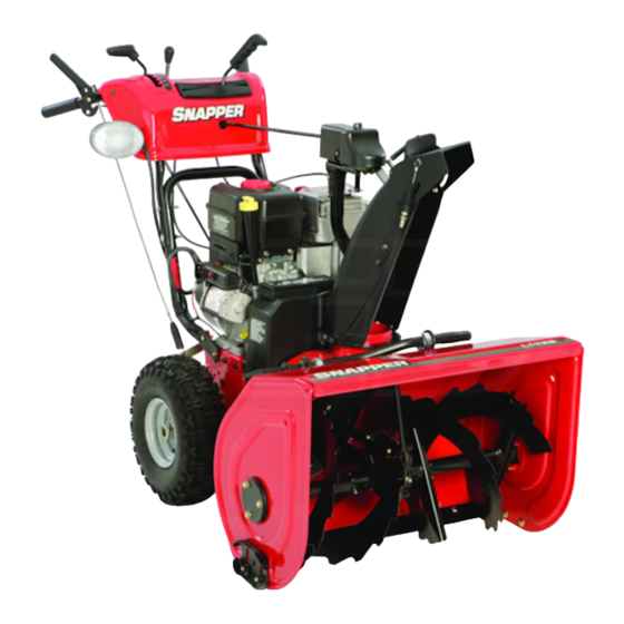
- Page 1 ® Large Frame Snowthrower 1428 Model Mfg. No. Description 1695572 L1428E, Snowthrower, 130.887280 1736682 Revision 00 Rev. Date 07/2008 TP 191-4968-00-LW-SN...
-
Page 2: Table Of Contents
Table ofContents CONTENTS: Starting the Engine ........Stopping the Engine ........Safety Rules & information Operating the Snowthrower ......General ............Clearing a Clogged Discharge Chute ... 21 Training ............Ground Speed Selector ........ Preparation ............. Engine Speed ..........Operation ............ - Page 3 Congratulations on purchasing a superior-quality piece of lawn and garden equipment. Our products are designed and manu- factured to meet or exceed all industry standards for safety. Power equipment is only as safe as the operator. If it is misused, or not properly maintained, it can be dangerous! Remember, you are responsible for your safety and that of those around you.
- Page 4 SafetyRules & Infomati(m M0vJflg This equipment has many moving parts that can injure you or someone else. However, if you are standing in the operator's position, and follow all the rules in this book, the unit is safe to operate. The auger and impeller have spinning parts that can amputate hands and feet.
- Page 5 SafetyRules & Informtm This machine is capable of amputating hands and feet and throwing objects. Read these safety rules and follow them closely. Failure to obey these rules could result in loss of control of unit, severe personal injury or death to you, or bystanders, or damage to property or equipment. The triangle in text signifies important cautions or warnings which must be followed.
-
Page 6: Clearinga Clogged Discharge
Safety Rules & information 21. Keep in mind the operator is responsible for acci- 8. Always follow the engine manual instructions for stor- dents occurring to other people or property. age preparations before storing the unit for both short 22. Data indicates that operators, age 60 years and and long term periods. -
Page 7: Decals
Decals DECALS The safety decals below are on your unit. This unit has been designed and manufactured to provide you with the safety and reliability you would expect from an If any of these decals are lost or damaged, replace them at industry leader in outdoor power equipment. -
Page 8: Safety Icons
Safety icons SAFETY iCONS WARNING: READ OPERATOR'S MANUAL. WARNING: DISMEMBERMENT. Read and understand the Operator's This machine can amputate limbs. Manual before using this machine. Keep bystanders and children away when engine is running. DANGER: THROWN OBJECTS. DANGER:DISMEMBERMENT. This machine is capable of throwing objects and debris. - Page 9 AssemhJy YOU WILL NEED: Traction Auger • Utility knife Engage • Unleaded fuel Control Chute • Tire pressure gauge Rotator Control • 1/2" deep socket wrench or combination • 9/16" deep socket wrench or combination Split Rod • 7/16" wrench ITEMS INCLUDED: Fuel Ca Chute...
-
Page 10: Raise Handles And Check
AssemhJy REMOVE PACKAGING MATERIALS Note: Follow setup instructions in the order pre= sented. 1. Remove banding from crate. Open carton completely by cutting each corner from top to bottom as shown in Figure 3. Open small cardboard box behind snowthrower. Remove parts bag from inside chute. - Page 11 AssemhJy CONNECT SHIFT ROD Connect shift rod (A, Figure 7) to shift lever (B) and secure with lock washer (C) and 5/16 lock nut (D). Tighten lock nut with a 1/2" wrench while preventing stud (E) from turning with a 7/16" wrench. ASSEMBLE CHUTE AND ROTATOR 1.
-
Page 12: Brake Cable
AssembJy CONNECT SPOUT ROTATOR BRAKE CABLE 1. Slide spout rotator brake cable (A, Figure 11) between dash and the handle cross bar as shown. 2. Slide rubber dust cover (B) off of plastic fitting as shown. 3. Place "Z" bend of cable (C) into hole of brake lever assembly (D). -
Page 13: Engine
AssembJy SECURE CABLE AND FINAL CHECKS To prevent chute deflector cable from contacting tire, rotate chute all the way to the left and secure with zip ties (A, Figure 14). Secure cable to left handle (B) and to support tube (C), and secure speed selector cable to split rod (D). - Page 14 Features, C ontrols, & Operation CONTROL LOCATIONS IMPORTANT NOTE Please take a moment and familiarize yourself with the The information below briefly describes the function name, location, and function of these controls so that you of individual controls. Starting, stopping, and driving will better understand the safety and operating instruc- require the combined use of several controls applied tions provided in this manual,...
- Page 15 Features & Controls (_) Starter 1,2.. Speed Selector Selects forward speeds 1-6 and reverse speeds 1-2. No Electric Start: Depressing the starter button activates neutral position or gate is required, since the traction the electric starter. The electric start button operates drive design automatically provides "neutral"...
- Page 16 OperstJon GENERAL OPERATION WARNING This unit is a "two=stage" snowthrower. CHECKS BEFORE EACH START=UP The first stage is the auger, which feeds the snow 1. Make sure all safety guards are in place and all nuts, back into the impeller housing.
- Page 17 OperstJon STARTING CONTROLS See Figure 17 for the following instructions. Electric Start Electric Start Button - The Electric Start Button (A) activates an electric starter mounted to the engine, eliminating the need to pull the starter handle. The Electric Start Button operates on 120 Volts AC, which is provided by connection to the extension cord pro- vided with units equipped with this feature.
- Page 18 Operation STARTING THE ENGINE A CAUTION WARNING This engine was shipped from Briggs & Stratton with oil. Before you start the engine, make sure Rapid retraction of starter cord (kickback) will you check oil according to the instructions in the pull hand and arm toward engine faster than you Engine Owner's Manual.
- Page 19 (Jperstion NOTE: If the engine does not start after three attempts, see the "Troubleshooting" section in the Engine Owner's Manual. 11. Allow the engine to warm up for several minutes. Then, slowly move the choke control knob to the run position.
-
Page 20: Chute
OperstJon OPERATING THE SNOWTHROWER A WARNING 1. Rotate the discharge chute to the desired direction. When BOTH levers are depressed, the Free= 2. Set the speed selector to the desired forward speed. Hand Control is activated. This allows Auger Engage Control to be released m YET AUGER 3. - Page 21 OperstJon GROUND SPEED SELECTOR Use the speed selector (A, Figure 21) to control the drive speed of the snowthrower. There are six forward speeds and two reverse speeds. Use the lower speeds to blow deep or wet snow. Use the higher speeds to blow light snow or to drive the snow- thrower without blowing snow.
- Page 22 Operation FULL TRACTION EASY TURN TRACTION Easy Turn TM Lever Turn Released Lever Engaged Both Wheels Drive Left Wheel Freewheels, Figure 24. Easy Turn Control Right Wheel Drives EASY TURN FREEWHEELING TRACTION DRIVE LOCK While Clearing Snow: For easy turning when using the snowthrower, squeeze the Easy Turn lever (Figure 24).
- Page 23 OperstJon AFTER EACH USE STORAGE Normal use of the snowthrower may result in a build-up of packed snow in and around the starter cord housing WARNING and around engine controls. Heat from the engine will usually prevent the snow from freezing solid while the Never store the unit (with fuel) in an enclosed, unit is running, but after the engine is shut down, some poorly ventilated...
- Page 24 Regular M aintenance MAINTENANCE SCHEDULE Maintenance Required Frequency Notes Check/Lubricate Free-Hand Linkage. 10 Hours 10W Oil Lubricate snowthrower. 10 Hours 10W Oil and Grease Check tire pressure. Monthly 20 psi (1,38 bar) Change engine oil.*+ 50 Hours See Engine Manual Yearly See Engine Manual Clean or replace...
- Page 25 ReguJap Maintenance LUBRICATION iMPORTANT NOTE it is very important that grease fittings on the auger shaft are lubricated regularly, if auger rusts to shaft, damage to worm gear may occur if shear pins do not break. To prevent wheels rusting to axles, it is also nec= essary to remove the wheeJs and grease the axles regularly.
-
Page 26: Linkage
ReguJap Maintenance CHECK / LUBRICATE FREE-HAND LINKAGE Check the function of the Free=Hand controls. The con- trois should function as described in the CONTROLS section. It is critical for the safe operation of the unit that the controls disengage when released. Lubricate as shown in Figure 32. - Page 27 Troubleshooting, , & Service TROUBLESHOOTING WARNING This section provides troubleshooting and service instruc- Before performing any adjustment or service to tions. Locate the problem and check the possible cause/ snowthrower, stop the engine and wait for mov= remedy in the order listed. ing parts to stop.
- Page 28 Problem Possible Cause Remedy Chute deflector too low. Auger rotates, but snow is not= Adjust deflector as necessary, thrown far enough. Engine speed too slow. Set speed to full throttle. Ground speed too fast. Use slower speed selector setting. Snowthrower discharge chute STOP engine and REMOVE the key.
- Page 29 Adjustments AUGER DRIVE ADJUSTMENT WARNING Do not over=tighten, as this may lift the lever and cause auger drive to be engaged without depress= ing the Auger Control. 1. Check that the auger cable (A, Figure 34) is on top of cable button (B) as show in Figure 34.
- Page 30 Adjustments 4-5/16" (10.95cm) Figure 36. Traction Drive Cable Adjustment Figure 37. Friction Disc Measurement Run=in Adjustment 1. After 5 hours of use, check for proper adjustment. Readjust clutch cable if necessary by increasing ten- sion on cable. A small amount of arm movement is permissible if unit passes operating checks described in the Warning above.
- Page 31 Adjustments EASY TURN CABLE ADJUSTMENT If the Easy Turn cable has stretched, the gears will not disengage when the control lever is activated. Adjust the cable using the following procedure. 1. Turn the engine off and disconnect the spark plug wire.
- Page 32 Adjustments & Service SHEAR PIN REPLACEMENT WARNING Do not go near the discharge chute or auger when the engine is running. Do not run the engine with any cover or guard removed. Under most circumstances, if the auger strikes an object which could cause damage to the unit, the shear pin will break.
- Page 33 SGPvic6 BELT REPLACEMENT Auger Drive Belt The drive belts are of special construction and must be replaced with original factory replacement belts avail- able from your nearest authorized service center. Some steps require the assistance of a second person. If the auger drive belt is damaged, the snow thrower will not discharge snow.
- Page 34 Adjustments & Service NOTE: To assemble the auger housing to the frame, have someone hold the auger clutch lever in the ENGAGED position. This will move the idler arm and pul- ley enough to allow the auger drive pulley to move back into position.
- Page 35 SGPvic6 Traction Drive Belt If the snow thrower will not move forward, check the trac= tion drive belt for wear or damage. If the traction drive belt is worn or damaged, replace the belt as follows. 1. Disconnect the spark plug wire. 2.
- Page 36 NOTE: Specifications are correct at time of printing and are subject to change without notice. * The gross power rating for individual gas engine models is labeled in accordance with SAE (Society of Automotive Engineers) code J1940 (Small Engine Power & Torque Rating Procedure), and rating performance has been obtained and corrected in accordance with SAE J1995 (Revision 2002-05).
- Page 37 TECHNICAL MANUALS Additional copies of this manual are available, as well as Replacement parts are available from your authorized fully illustrated parts lists, dealer. Always use genuine Snapper Service Parts. Technical manuals can be downloaded from www.snap- per.corn MAINTENANCE ITEMS...
- Page 38 Notes:...
- Page 39 PRODUCTS 535 Macon Street McDonough, GA 30253 www.Snapper.com © Copyright 2008, BRIGGS & STRATTON. All Rights Reserved. Printed in USA.
- Page 40 ® USUAR|O Lanza or de nieve maEo grande Modelo 1428 Mfg. N°: Descripcion 1695572 L1428E, Lanzad0r de nieve 130.887280 1736682 RevisiOn 00 Fecha de rev. 07/2008 TP 191-4968-00-LW-SN...
- Page 41 decoflteflidos CONTENIDOS: Comprobaciones previas a cada arranque .. 17 Mandos de inicio .......... Normas de seguridad e informacion Encender el motor ........General ............Apagar el motor ..........Practica ............Manejar el lanzador de nieve ....... Preparacion ............ Limpiar el conducto de descarga Funcionamiento ..........
- Page 42 NI)PmSS Msnejsr equipo conseg Felicidades pot haber adquirido un equipo dejardfn y campo de alta calidad. Nuestros productos estan disenados y fabricados para cumplir o exceder todas las normas de seguridad del sector. El equipo electronico solamente es seguro en la medida en Io que Io utiliza el operador.
- Page 43 Norms de seuuridsde iflformcidfl Piezss m6viles Este equipo tiene piezas moviles que le pueden causar danos a usted o a otras personas. Sin embargo, si usted se mantiene en la posicion del operario, y sigue las instrucciones proporcionadas en esta manual, esta unidad es segura. El tornillo sinfin y el impulsor tienen partes giratorias que pueden amputar manos y pies.
- Page 44 REGLAS PARA OPERACION SEGURA Esmaquina escapaz deamputar manos y piesy arrojarobjetos.Leaestasnormas de seguridad y respetelas e strictamente. El no respetar estasnormas podr[aresultar en perdida de controlde la unidad,lesiones personales g raves o muerte paraustedo transe0ntes, o da_osa la propiedad o equipo.Eltriangulo_ enel textosignificaprecauciones o advertencias i mportantes q uedebenrespetarse.
- Page 45 REGLAS PARA OPERACION SEGURA N NOS 8. Siempre sigalasinstrucciones demanual delmotorparapreparaciones paraalmacenaje, antes dealmacenar la unidad, tantopara periodos Pueden ocurriraccidentes %gicossi eloperador no esta atento a la cortoscomolargos. presencia d eninos.Losninossuelen sentirse atra[dos a la unidad ya la 9. Siempre sigalasinstrucciones delmanual d emotorpara actividad deoperaciOn.
- Page 46 EtJquetas ETIQUETAS Esta unJdad ha sido disehada y fabricada para La informacion es para su seguridad yes importante. proporcionarle la seguridad y fiabilidad que espera de un En su unidad se encuentran las siguientes etiquetas de lider en la industria en equipos electricos de exterJores. seguridad.
- Page 47 Iconos de seguridad ICONOS DE SEGURIDAD ADVERTENCIA: LEA EL MANUAL DEL ADVERTENCIA: DESMEMBRAMIENTO. USUARIO. Esta maquina puede amputar Lea y comprenda el manual del usuario miembros. No permita a personas ni a ninos estar cerca con el motor en antes de utilizar esta maquina, funcionamiento.
- Page 48 AssembJy ELEMENTOS NECESARIOS: Control de Controlde • Navaja embrague de la barrena • Combustible sin plomo Control de rotaci6n de • IVlan6metropara neum_ticos la rampa • Llavede cubo combinada o alargada de 1/2 pulg • Llavede cubo combinada o alargada de 9/16 de pulg Varilla de •...
- Page 49 AssembJy REMOCION DE LOS MATERIALES 2. Alinee el asa del control de rotacion de la tampa de modo que quede de ffente y utilice una Ilave de 9/16 EWIBALAJ de pulg. para apretar la tuerca autoblocante (A) en el Nota: Siga las instrucciones de monta]e en el orden asa del control de rotacion de la tampa (B).
- Page 50 AssemhJy CONEXION DE LA VARILLA DESLIZAMIENTO Conecte la varilla de deslizamiento (A, Figura 7) a la palanca de cambios (B); asegurela con la aran- dela de retencion (C) y la contratuerca de 5/16 (D). Apdete la tuerca con una Ilave de 1/2 pulg. y evite que el extremo (E) gire con ayuda de una Ilave de 7/16 de pulg.
- Page 51 AssembJy CONEXJON DEL CABLE DEL FRENO DEL DiSPOSITIVO DE ROTACION VERTEDERO Deslice el cable del freno del dispositivo de rotacion del vertedero (A, Figura 11) entre el tablero de instrumentos y la barra transversal del asa, como se muestra. Desconecte la proteccion de goma (B) del elemento de fijacion de plastico como se muestra.
- Page 52 AssembJy FUACION DEL CABLE Y COMPROBA- CIONES FINALES Para evitar que el cable de deflexion de la tampa entre en contacto con el neumatico, gire la tampa completamente hacia la izquierda y fije con cinchos (A, Figura 14). Fije el cable al asa izquierda (B) y al tubo de apoyo (C), y fije el cable del selector de velocidad a la varilla de division (D).
- Page 53 Csrscteris|icss, rondos, y UBICACION DE LOS MANDOS AVISO IMPORTANTE Por favor, tomese un momento para familiarizarse con La siguiente informacion le describe brevemente la el nombre, ubicacion y funcion de estos mandos para funcion de los mandos individuales. Arrancar, parar y que puede comprender mejor las instrucciones de conducir requieren la utilizacion combinada de varios funcionamiento y seguridad que contiene este manual.
- Page 54 Caracteristicas y mandos 1,2.. Selector de velocidad Motor de arranque Selecciona marchas hacia adelante de la 1 a la 6, y Arranque electrico: AI pulsar el boron de arranque marchas atras de la 1 a la 2. No se necesita punto se activa el arranque electrico.
- Page 55 Funcionamiento FUNCIONAMIENTO ADVERTENCIA GENERAL Esta unidad es un lanzador de nieve en "dos rases". COMPROBACIONES PREVIAS La primera fase es el tornillo sinfin, que introduce la nieve en la carcasa del impulsor. La segunda CADA ARRANQUE fasees el impulsor, que lanza la nieve por la boquilla de descarga.
- Page 56 Funcionamiento MANDOS DE INICIO Vea la Figura 17 para las siguientes instrucciones. Arranque electrico A. Boton de Arranque Electrico - El Boton del arranque electrico (A) activa un arranque electrico instalado en el motor, eliminando la necesidad de pulsar el arranque. El boton de arranque electrico funciona con CA de 120 V, que se proporciona mediante la conexion al cable electrico proporcionado.
- Page 57 Funcionamiento ENCENDER EL MOTOR A PRECAUCION ADVERTENCIA Este motor ha sido enviado desde Briggs & Stratton con aceite. Antes de arrancar el motor, La retraccion rapida o el cable de arranque asegurese de que comprueba el nivel de aceite (Kickback) empujara la mano y el brazo hacia segun las instrucciones...
- Page 58 Funcionamiento NOTA: Si el motor no arranca despues de tres intentos, vea la seccion de "Resolucion de problemas" en el Manual de instrucciones del motor. 11. Deje que el motor caliente durante varios minutos. Despues, mueva lentamente la perilla del estrangulador a la posicion de encendido.
- Page 59 Funcionamiento MANE JAR EL LANZADOR DE NIEVE ADVERTENCIA 1. Gire la boquilla de descarga a la direccion deseada. Cuando AMBAS palancas se presionan, se activa 2. Coloque el selector de velocidad en la marcha hacia el control Free-Hand Esto permite que se adelante deseada.
- Page 60 Funcionamiento paralelas a la superficie. SELECTOR DE VELOCIDAD 5. Para bajar la altura de la barra, levante las zapatas. TIERRA O a]uste la barra afiojando los pernos y deslizando la Utilice elselector d e velocidad (A,Figura21)para barra hacia abajo. velocidad de conducciondel controlar la lanzador 6.
- Page 61 Funcionamiento TOTAL TRACCION TRACCION EASY TURN Palanca Palanca Easy Turn Easy Turn liberada liberada Avarice sin traccion rueda izquierda, Traccion a ambas ruedas traccion rueda derecha Figura 24. Control Easy Turn MOVIMIENTO SIN TRACCION EASY TURN TMY BLOQUEO DE TRACCION Mientras aparta la nieve:...
- Page 62 Funcionamiento DESPUES DE CADA UTILIZACION ADVERTENCIA la utilizaci0n normal del lanzador de nieve puede Nunca guarde la unidad con gasolina en el provocar una acumulacion de nieve empaquetada motor o combustible en el deposito, en un lugar alrededor de la carcasa del cable de arranque y templado o cerrado, ni en lugares cerrados alrededor de los mandos del motor.
- Page 63 MantenJmiento regular PROGRAMA DE MANTENIMIENTO Mantenimiento requerido Frecuencia Notas Verificar / Lubricar union Free-Hand 10 Horas Aceite 10W Lubricar el lanzador de nieve. 10 Horas Aceite y Grasa 10W Verificar la presion de los neumaticos. Mensualmente 1,38 bar (20 psi) Cambiar el aceite del motor.*+ 50 Horas Ver Manual del motor...
- Page 64 MantenJmJento regular LUBRICACION AVlSO IMPORTANTE Es muy importante que las adecuaciones para grasa en el e]e del tomillo sinf|n se lubriquen regularmente. Si el tornillo sinf|n se oxida hasta el eje, puede ocurrir un daho al engranaje de tornillo si los pemos de seguridad no se rompen.
- Page 65 Maflteflimiefltu regular COMPROBACION ! LUBRICAR ENLACE FREE-HAND Verificar lafunci0n de loscontroles d e Free-Hand Los controles deben funcionar como se describe en la seccion de CONTROLES. Es cr|tico para la operaciOn segura de la unidad el que los controles se suelten cuando se liberen.
- Page 66 reparaciones prOblBfllBS, RESOLUCION DE PROBLEIVIAS ADVERTENCIA Esta seccion proporciona resolucion problemas e Antes de Ilevar a cabo algun ajuste o instrucciones de mantenimiento. Situe el problema y mantenimiento en el lanzador de nieve, detenga compruebe la causa posible/solucion en la lista. el motor y espere que se detengas las piezas moviles.
- Page 67 Resoluci6n de problemas Problema Posible causa Solucion El tornillo gira, pero la nieve no El deflector de la boquilla esta Ajuste el deflector Io necesario. se tira a la distancia suficiente. demasiado bajo. La velocidad del motor es demasiado Configure la velocidad al estrangulador lenta, total.
- Page 68 Ajustes AJUSTE DE LATRANSMISION TORNILLO SINFJN ADVERTENCIA No Io apriete en exceso, ya que podria levantar la palanca y accionar la transmision del tornillo sinf|n sin presionar el control del tornillo sinf|n. Compruebe que el cable de transmision del tornillo sinfin (A, Figura 34) esta en la cima del boton del cable (B) como se muestra en la Figura 34.
- Page 69 Ajustes 10.95 cm (4-5/16 pulg.) Figura 36. Ajuste del cable de transmisi6n de tracci6n Figura 37. Medicion del disco de friccion Ajustes TODOS LOS MODELOS 1. Despues de 5 horas de utilizacion, compruebe los ajustes. Reajuste el cable del embrague si es necesario aumentando la tension sobre el cable.
- Page 70 Ajustes AJUSTE DEL CABLE EASY-TURN Si el cable Easy Turn esta estirado, las marchas no se desacoplaran con la palanca de control activada. Ajuste el cable utilizando el siguiente procedimiento. 1. Apague el motor y desconecte el cable de la bujfa. 2.
- Page 71 Ajustes y mantenJmJento REEIVIPLAZO DE PERNO SEGURIDAD ADVERTENCJA No se acerque al conducto de descarga o tornillo sinf|n cuando el motor este funcionando. No haga funcionar el motor sin la cubierta o proteccion, Bajo la mayoria de circunstancias, si el tornillo sinfin golpea un objeto que pudiese causar un dano a la unidad, el perno de seguridad se rompera.
- Page 72 Mantenimiento CAMBIO DE LA CORREA Correa de transmision del tornillo sinfin Las correas de transmision son de construccion especial y deben reemplazarse con las correas de reemplazo originales de fabrica disponibles en el centro de servicios autorizado mas cercano. Algunos pasos necesitan de la ayuda de una segunda persona.
- Page 73 Ajustes y mantenJmJento NOTA: Para montar la carcasa del tornillo sinffn a la estructura, alguien debe sujetar la palanca de embrague del tornfllo sinffn en la posicidn de ENGANCHADO. Esto movera la polea y brazo flotantes Io suficiente para permitir que la polea de la transmision del tornillo sinffn vuelva a su posicion.
- Page 74 Mantenimiento Correa de transmision de traccion Si el lanzador de nieve no avanza hacia adelante, verifique si la correa de transmision de traccion esta desgastada o danada. Si la correa de transmision de traccion esta gastada o danada, reemplace la correa como se indica a continuacion.
- Page 75 EspecJficaciofles NOTA: Las especificaciones son correctas en el momento de la impresidn y esta sujetas a cambio sin previo aviso. La clasificacion de potencia bruta para modelo de motor de gasolina individual esta etiquetada de acuerdo con el codigo J1940 (Smafl Engine Power & Torque Rating Procedure) de la SAE (Society of Automotive Engineers), y la clasificacion de rendimiento ha sido obtenida y corregida de conformada con SAE J1995 (Revision 2002-05) Los valores de fuerzas de torsion han sido derivados a 3060 rpm;...
- Page 76 Las piezas de recambio estan disponibles en su Tenemos a su disposicion copias adicionales de este distribuidor local. Utilice siempre piezas autenticas manual, as{ como listas de piezas totalmente ilustradas. Simplicity/Snapper. Puede descargar los manuales tecnicos desde www, snapper.corn ELEMENTOS...
- Page 77 Notas:...
- Page 78 S P£R PRODUCTOS 535 Macon Street McDonough, GA 30253 www.snapper.com ® Copyright 2008, BRIGGS & STRATTON. Reservados todos los derechos Impreso en EEUU.
Need help?
Do you have a question about the 1428 and is the answer not in the manual?
Questions and answers