Table of Contents
Advertisement
Owner's
Manual
6 6 4200 Series 5 asoline 6 enera#ors
Using a generator
indoors CAN KILL YOU IN MINUTES.
Generator exhaust
contains carbon monoxide.
This is
a poison you cannot see or smell.
NEVER use Inside a home
or garage, EVEN IF doors
and windows
are open.
Only use OUTSIDE and
far away from windows,
doors, and vents.
Utilizar un generador
dentro LE MATARA EN MINUTOS.
El escape contiene mon6xido de carbono, un gas
tbxico usted no Io puede ver nioler.
NUNCA utilice en el hogar ni
en _reas en parte encerradas
tales como garajes.
SOLAMENTE uselo fuera y
lejos de ventanas abiertas,
puertas, y respiraderos.
Do Not Return
To Store
One year or 60 Hours
Limited
Warranty
(see page 19)
For customer
service
or warranty
information
call toll free
866 797 2738
Read carefully
before attempting
to assemble,
install, operate
or maintain
the product
described.
Protect
yourself
and others by observing
all safety information.
Failure to comply with the user' s manual
could
result
in personal
injury
and/or
property
damage!
retain
the user's
manual
for future
reference.call
toll free number
866 79 7 2738 for parts
and service.
DISCLAIMER:
All pictures
may not be identical
to product
inside
box.
Distributed
by _Fullerton,
CA 92833
Advertisement
Table of Contents

Related Manuals for UST GG4200 series


Summary of Contents for UST GG4200 series
- Page 1 Owner's Manual 6 6 4200 Series 5 asoline 6 enera#ors Using a generator indoors CAN KILL YOU IN MINUTES. Generator exhaust contains carbon monoxide. This is a poison you cannot see or smell. NEVER use Inside a home Only use OUTSIDE and far away from windows, or garage, EVEN IF doors and windows...
- Page 2 SAFETY ALERT SYMBOL: Indicates danger, warning, or caution.Attention required in order to avoidserious personal injury. The signal word (DANGER, WARNING, or CAUTION) is used with the alert symbol to alert you to special instruction about a particular operation that may be hazardous if pe rformed incorrectly or carelessly.
- Page 3 CONTENTS 1 .SAFETY ..............2.COMPONENT IDENTIFICATION ......... 3.PRE-OPERATION CHECK ..........4.STARTING THE ENGINE ..........5.GENERATOR USE ............6.STOPPING THE ENGINE ..........7.MAINTENANCE ............8.STORAGE ..............9.TROUBLE SHOOTING ............ 10.WIRING DIAGRAM ............11.SPECIFICATIONS ............12.PARTS LISTAND DIAGRAM .......... 12.1 CRANKCASE ASSEMBLY ..........
-
Page 4: Parts
1. SAFETY 1.1 SAFETY LABELS Using a generator indoors KILL IN MINUTES. Util]zar un generador dentro LE MATARA EN MINUTOE. This generator produces high voltage Generator exhaust contains carbon monoxide. This El escape contlene mondxldo de carbono, un gas RISK OF ELECTRICAL SHOCK ALWAYS... -
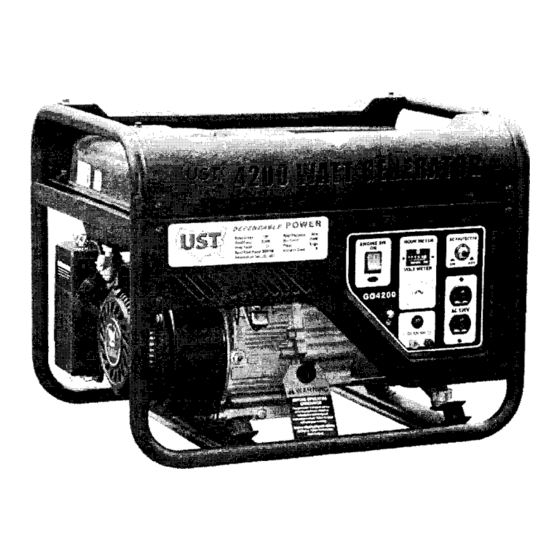
Page 5: Component
1.2 GENERATOR SAFETY !jji ilii DO NOT USE INSIDE HOUSE. DO NOT CONNECT DO NOT USE IN WET SURROUNDING. HOUSEHOLD CIRCUIT. © KEEP FLAMMABLE MATERIAL NO SMOKING. DO NOT SPILL. STOP ENGINE. AT LEAST 1m(3FT)AWAY. BEFORE REFUELING 2.COMPONENT IDENTIFICATION 1. FUEL TANK CAP 2. -
Page 6: Pre-Operation
3.PRE-OPERATION CHECK 1.OIL LEVEL CAUTION: Be sure to check the generator engine fluid levels with the generator on a level surface Recommended oil:4-stroke motor oil service classification SJ,SL, SG or SAE 10W-30 for general temperature. 1.Remove the oil filler cap/dipstick wipe off any oil. - Page 7 3.AIR CLEANER 1.Unsnap the air cleaner cover springs,and remove the air cleaner cover 2.Checkthe air cleaner element to be sure it is clean and in good condition. (1)Wash in solvent 3.If it is dirty, remove and clean (2)Squeeze the element. (3)Soak oil (4)Squeeze dry 4.Reinstall...
- Page 8 _-----:::;J i i .2 i! z'._&} 5.Pullthe starter grip lightly until resistance is felt then pull briskly. 6.Move choke lever to the right "OPEN" position Warning:Do not allow the starter grip to snap back against the engine. as the engine warms Return it gently.
- Page 9 3.When two or more pieces of apparatus are connected your generator,turn them on beginning with the one drawing higher current when starting. AC APPLICATION 1.Start the engine 2.Make sure that the needle of the voltmeter indicates the voltage. 3.Plug in the appliance Note: a:Over current will automatically turn off the AC breaker.
-
Page 10: Stopping
DC APPLICATION The DC terminals may be used for charging 12V automotive-type batteries only 1.Connect the charging cables to the battery terminal. 2.Start the engine and charge the battery NOTE: An overloaded DC circuit will trip the DC circuit breaker ©... -
Page 11: Maintenance
7.MAINTENANCE Check-Readjust Check Clean (_Change SEE page Evet_rYear Firstmonth Every 3months Engine Air cleaner Fuel strainer Battery fluid level Spark plug Valve Clearance Combustion Chamber Fuel line _(1)(2) (1):These items shoule be serviced by a dealer. (2):Every 3 years 1.OIL CHANGE 1.Remove the oil filler cap. -
Page 12: Storage
2.AIR CLEANER(See 3 page) 3.SPARK PLUG SPARK PLUG TYPE: F7RTC 1.Remove the spark plug cap. 2.Remove the spark plug. .8m_.031in) 5.Reinstall the spark 4.Measure the gap. plug and plug cap. 3.Clean the deposit. 4.FUEL STRAINER 1.Turn the fuel valve 2.Clean the sediment to the OFF position cup and fuel filter... -
Page 13: Trouble
9.TROUBLE SHOOTING ENGINE DOES NOT START: 2. Check fuel lever and 3.Check oil. 1.Turn on the engine switch. fuel ON/OFF valve. Engine will not start unless oil level is correct. 5.Check spark. 4.Remove spark plug. Hold spark plug against metal, pull the recoil starter to see spark. -
Page 14: Wiring
10.WIRING DIAGRAM GF_OU N _ l L_r,'l'q .',L "r DCPROTECTER 11.SPECIFICATIONS Package(LXWX H)(in) 23.62X 17.12X 18.5(600x435X470) Net weight(Ibs) 88(40kg) Model GG4200 Type Single phase Rated voltage(V) Rated frequency(Hz) 26.7 Rated current(A) Rated power(kW) Surge power(kW) Power factor (cos ( do )) DC rated voltage DC rated current(A) N.F.B... - Page 15 12.PARTSLISTAND DIAGRAM. 12.1 CRANKCASE ASSEMBLY PARTS NO. DESCRIPTION GB/T5787 BOLT QJ168QDJ.01-01B COVER, crankcase QJ168QDJ .01-05 WASHER, seal QJ168QDJ .01-04 GUAGE, engine oil QJ168QDJ .01-03 COVER, supply oilmouth 157.3-8 GUIDE, dowel QJ168QDJ .01-02 SPACER, crankcase GB/T5787 BOLT QJ168FJH-3.01.02 SENSOR ASSY, fuel level QJ168QDJ.01.01 OILSEAL...
- Page 16 12.3 INTAKE & EXHAUST MECHANISM ASSY. PARTS NO. DESCRIPTION ADJUSTING NUT, valve QJ166QDK.03-11 clearance QJ182QDR03-07 BUTTONHEAD, arm QJ168QDJ.03-09 CAP, exhaust door QJ168QDJ.03-02 UPPER RETAINER, QJ168QDJ.03-10 exhaust door spring QJ 168QDJ.03-07 SPRING, valve QJ168QDJ.03-05 Valve, exhaust GUIDE PLATE, QJ168QDJ.03-03 onnecting stud QJ168QDJ.03.02 ROD, connecting UPPER...
- Page 17 12.5 CENTRIFUGAL ADJUSTMENT ASSY. PARTS NO. DESCRIPTION QJ168QDJ.05-01 QJWB.06.01-10 ROD, tension QJ168QDJ.05-06 SPRING 2, tension GB/T6177 QJ182QDR06-03 BOLT, square QJ168QDJ.05-09 SPACER QJ182QDP.06-02 ClRCLIP QJ168QDJ.05-03 FORK QJ166QDK.06-03 SPACER QJ168QDJ.05-04 QJ166QDK.01-02 CIRCLIP ADJUSTMENT, QJ168QDJ.05.02431 centrifugal QJ168QDJ.05.02-03 BLOCK, centrifugal QJ 168QDJ.05.02432 P IN QJ168QDJ.05-08 SPACER QJ168QDJ.05-02...
- Page 18 12.7 STARTING SETASSY. PARTS NO. DESCRIPTION QJ168QDJ.06-05 SCREW QJ168QDJ.06-06 CIRCLIP QJ168QDJ.06-04 PLATE, guide QJ168QDJ.06-01 BLOCK, clutch QJ168QDJ.06-02 SPRING, pressure QJ168QDJ.06-03 TABLE, rotary "2 QJ168QDJ.06-07 SPRING, turbination GB/T5789-1986 BOLT M6X8 QJ168QDJ.06.01 COVER, starting QJ168QDJ.06-08 ROPE, starting QJ168QDJ.06-09 HANDLE QJ 168QDJ.06.02.02 COWLING GB/T5789 BOLT M6xl0...
- Page 19 12.9 CARBURETORASSY. PARTS NO. DESCRIPTION QJ168FLH-4.04.01 CARBURETORASSY 153FM-0000041 CIRCLIP QJ168QDJ.10.03-02 JACKET QJ168FJH-3.07-02 JOIN PLANK HOSE, oil QJ168QDJ .10.03-01 12.10 GENERATOR PART NO DESCRIPTION GB/T5787-86 Bolt M5"8 ,_ _._ : QJ2500.03-02 Right Side Cover GB/T5789-86 Screw QJ2500.02.05 Rectifier " i QJ2300.03.03 Carbon Brush _ '------_-_ GB/T5787-86...
- Page 20 12.11 GAS TANKASSEMBLY PART NO DESCRIPTION KE3500D.01.01 Fuel Tank QJ6000.01.04 Fuel Tank QJ950.01-02 Filtering QJ6000.01.03 Sender Unit GB/T819.1-2000 Screw M5"10 GB/T5789-86 Bolt M6"20 GB/T96.2-2002 Washer QJ2600.01-02 Fuel Tank Rubber H0se QJ2600.01-01 Fuel Tank Rubber QJ2600.01.02 Fuel Valve 12.12 PANEL PART NO DESCRIPTION KE3500D.02.01B Panel...
- Page 21 MUFFLER 12.13 PART NO DESCRIPTION QJ3200.02.01, _ Muffler QJ2900F.04-01 Muffler Cover 12.14 FRAME PART NO DESCRIPTION KE3500D.06.01B Frame KE3500D.06-01 Frame Cover GB/T5789-86 FlangeFace Bolt M6"10 Left andRightShockproof QJ2600.08.02 MountingFeet GB/T6177.1-2000 Flange Face NutM8 Right Shockproof QJ2500.04.02 Mounting Feet Warranty and Service Questions Missing or Damaged...
-
Page 22: Product
If the problem is not corrected as a result of the phone or email contact, IMS-UST at its option will evaluate the issue and will authorize a repair or replacement of the defective part of the unit. - Page 23 PRODUCT REGISTRATION CARD For more efficient customer service, please fill out the infolnlation below and mail to International Merchandis- ing Service,lnc Model No. Engine Serial No. Purchase Date Purchased from: [ ]Retail location [ ] Private Consmner []Other Name" Location Address: Purchase Price: Telephone w/area code: Purchased:[ ] NEW or [ ]USED...
Need help?
Do you have a question about the GG4200 series and is the answer not in the manual?
Questions and answers