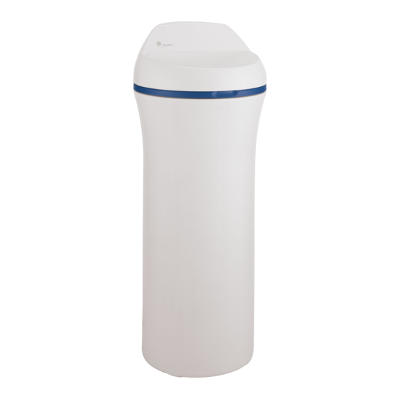
GE GXSF27E Owner's Manual & Installation Instructions
Water softening system
Hide thumbs
Also See for GXSF27E:
- Owner's manual & installation instructions (60 pages) ,
- Owner's manual & installation instructions (60 pages)
Table of Contents
Advertisement
Available languages
Available languages
Quick Links
www.GEAppliances.com
©
Safety Information
...........
2
Installation
Instructions
...3-1 o
Step-by-step instructions
.... 6-10
Operating
Instructions
Breaking
a salt bridg_
........
19
Cleaning
the nozzle
and
venturi
assembly
............
19
Features
...................
13
Service
..............
11, 14-16
V(ater softener
system
.....
11-16
Care and Cleaning
.........
17
Troubleshooting
Tips .....
18-20
Consumer
Support
Consumer
Support
. . .Back Cover
Parts list/catalog
.........
92-25
V_'arranty (U.S.)
.............
96
_'arrantv
(Canada)
..........
97
Water Softening
System
Sistema
Model GXSF27£
Suavizante
de Agua
Modelo GXSF27E
La secci6n
en espa#ol empieza en la pagioa 29
System
tested
and certified
by NSF International
against
NSF!ANSI
Standard
44 fl)r the
chemical
reduction
(laims
specitied
on the
per/brmance
data sheet.
Sistema
probado
y certiticado
pot
NSF International
contra
norma
44 de NSF/ANSI
para
las afirmaciones
de reduccidn
de los productos
qufmi(os
especi/icadas
en la hoja
de datos
de flmcionamiento.
Write themodel and serial
numbers here:
Model #
Serial #
To find these numbers, lift
the cover and look on the
rim below the control panel.
7247182
215Cl173P009
49-50150
02-05 Jfl
Advertisement
Table of Contents

Related Manuals for GE GXSF27E


Summary of Contents for GE GXSF27E
- Page 1 www.GEAppliances.com Water Softening Safety Information ... Installation Instructions ...3-1 o System Step-by-step instructions ..6-10 Operating Instructions Breaking a salt bridg_ ..Cleaning the nozzle venturi assembly .... Model GXSF27£ Features ....Service ....11, 14-16 Sistema Suavizante V(ater softener system ..
-
Page 2: Important Safety Information
IMPORTANTSAFETYINFORMATION. READALL INSTRUCTIONSBEFORE USING. WARNING! For your safety, the information in this manual must be followed to minimize the risk of electric shock, property damage or personal injury. SAFETY P RECAUtiONS _: Check cmnl)ly with vour state and local _: Use clean water softening salts only, at least codes. -
Page 3: Installation Instructions
Installation instructions. A_ CAUTION: Certain plumbing skills are needed for installation. If you are unsure about any part of the installation of this product, consult a professional plumber. Unpacking and Inspection Be sure to check the entire softener for any Small parts needed to install... -
Page 4: Where To Install The Softener
3/4" (nominal) Col)per sweat tubes. GE Parts at 800.626.2002. You should maintain the same, or larger, pipe size as the water supply pipe, up to the ::Ji:: If a rigid wdve drain... -
Page 5: Typical Installation Illustration
Typical Installation Illustration Fig. 1 CROSSOVER /V47_R P /PE Softwater Useif water supplyflows from the left. Includesingle or 3-valvebypass. -_ "_'--- H ardwater Hard water "_-__.._L Hardwater to outsidefaucets Softwater 120-voltoutlet Union (not supplied) (2) 24V transf( Fromsoftener, (_-_ Installation nut (2) )utlet ,_ To softener inlet... - Page 6 Fig. 3% VIEW • Snap the 2 lm'ge plasdc clips in place, fi'om the top, down as sho_m in Figures 3A ml(t 3B, Be sure they snap into place. Pull on the bypass valve to make sure it is held securely in place.
- Page 7 #,4.CONNECTING A RIGIDVALVE DRAINTUBE Fig4A 1/4" NPTthreads To adapt a copper drain tube to the soiteneL use a hack_m to cut the barbed end fl'om the 1/2" O.D. drain fitting as shown in Fig. 4A. Rotale file drain fitting st) file cutting blade clears file xahe housing u) pre\ent damage to valve.
- Page 8 Step-by-step installation instructions. SET WATERHARDNESS NUMBER Programming the Control I. Pressthe MODEbutton until HARDNESSappeax_ i n the display. 2. Press • or DO_VN • button to set your water hardness nmnber in tile display. DOWN decreases tile hardness xdue. UP increases tile hardness xdue.
- Page 9 ERRORSIGNALS Optional Control Settings ]f there is an error code detected, the displa_ I-.7. I- I- U The controller display has several options and teatures. will flash Err to signal that the sottener L..........SYSTEM/ELECTRONIC DIAGNOSTICS requires se_Ti('e. See page 14 ti)r inflmnation m assist in troubleshooting This display contains s?'stem diagnostics...
-
Page 10: Sanitizing Procedures
Step-by-step installation instructions. Sanitizing Procedures 4. If, after sanitization, water fl'om the house To complete the installation, do the following fimcet tastes salty or has a slight col(n; this is sanitizing procedures. a preservative ti'om the resin tank. Tm'n on Care is taken at the factory to kee I) your... -
Page 11: About The Water Softener System
About the water softener system. GEAppliances. Service _Mter a period of time, tile resin beads become When tile water softening s):stem is providing coated with hard minerals and they have to be sott water, it is called "Service." During service, cleaned. -
Page 12: Breaking A Salt Bridge
About the water softener system. Breaking a Salt Bridge Pushtool into salt Sometimes, a hard crest or salt bridge forn_s in bridgeto break the salt storage area. It is usually caused by high humidity or the wrong kind of salt. When salt bridges, an empty space torms... - Page 13 GEAppliances.com Normal Operation, Control Displays During normal operation, tile present time dav and AM or PM show in the control display area. When tile demand comlmter determines a recharge RECHARGE TONIGHT is needed, begins to flash in tile display ahmg with tile RECHARGE TONIGHTflashes present...
- Page 14 About the water softener system. Service: Electronic Demand Time Features and Service ERROR CODE DISPLAYED ERR01 ERR 02 ERR 03 ERR04 ERR 05 POSSIBLE DEFECT • Motor • Motor • Control •Position •Position switch switch or inoperative inoperative or wiring wiring harness harness...
- Page 15 GEAppliances.com Service: Manually Initiated Electronics Diagnostics l':neSitches I. To enter diagnostics, press hold _._lfile in this diagnostic screen, the following infi)m_ation is available and may be benefidal for wuious reasons. MODE button until (000 --) shows in the fl'om the display.
- Page 16 About the water softener system. Service: Manually Advance Recharge Check NOTE: NOTE:The control display must show a steady If water system pressure is low, an time (not flashing). elevated drain hose may cause back pressure, stopping brine draw. I. Press the RECHARGE @ button hold in RECHARGE @ Again,...
- Page 17 To take water iron of water; tile over IllaxiIlltlIll clear watei" ii'on, an iron filter or other equipment is needed. GE recommends using only Diamond Crystal Red*Out e_brand salts with h'on Fighter additive to hel I) kee I) the resin clean clear iron.
-
Page 18: Troubleshooting Tips
Before you call for service... Troubleshooting -tips Save time and money! Review the charts on the following pages first and you may not need to carl for service. NO SOFF WATER--Most Common Problems: Check the following before calling for service: •... - Page 19 GEAppliances.com Problem Possible Causes What To Do Water hard sometimes Using hot water while the water • Avoid using hot water during water s()ftening system softeathag system is regenerating recharge, because tile water heater will refill with hard water: See Automatic Hard Water Bypass During Recharge section, page 11.
- Page 20 Before you call for service... Troubleshooting -tips Problem Possible Causes What To Do Salty tasting or Unit not sanitized • Conq)lete the Sanitization Procedures on page 10. brown/yellow colored • At ('(nnl)lefion of recharge, cycle, (approx, _2 hLO,_run water waterafter installation from timcets to purge the salty water: Low water pressure Check...
- Page 21 Notes. GEAppliances com...
- Page 22 Parts lisL "--"--- ,,.-30...
- Page 23 GEAppliances.com 146 147...
-
Page 24: Parts Catalog
Parts catalog. GENERAL ELECTRIC PARTS CATALOG REE NO. GE PART NO. PART DESCRIPTION (01) 0003 WS35X10001 O-RING SEAI, KIT 0004 WS34X10014 DECAl,, FACEPLATE 0005 WS07X10004 HOSE, DRAIN, 20 FT. 0007 WS14X10002 DISTRIBUTOR, 0008 WS14X10001 DISTRIBUTOR, BOTTOM 0009 WS01X10002 RESIN, 1 CU. FT. - Page 25 GEAppliances.com GENERAL ELECTRIC PARTS CATALOG REE NO. GE PART NO. PART DESCRIPTION (01) 0111 WS19X10005 SUPPORT SCREEN 0112 WS03X10013 SCREEN 0113 WS22X10020 FI,OW PI,UG, .10 GPM 0114 WS08X10005 GASKET & ASPIRATOR 0115 WS03X10015 (;ONE SCREEN 0116 WS22X10021 PLUG, FILL FLOW, .30 GPM...
- Page 26 Staple your receipt here. Servicer Network. To schedule service, on-line, 24 hours a day, vis# Proof of the original purchase us at GEAppfiances.com, or call 800.GE.CARES (800.432.2737) (U.S), date is needed to obtain service or 866.777.7627 (Cana da). under the warrantg For The Period Of."...
- Page 27 GE Water Softening System Warranty. (For C ustomers inCanada) All warranty service provided by our Factory Service Centers or an authorized technician. For service, call toll free 1.866.777.7627. For The Period Of." We Will Replace: One Year Any part of the _,_ater Softening S,_;stem whi(h...
- Page 28 Notes.
- Page 29 Informaci6n de seguridad ..Instrucciones para instalaci6n ....31-39 Instrucciones paso pot paso ...34-39 Instrucciones para la operaci6n C6mo limpiar la ensambladura de la boquilla y el Venturi ..C6mo romper un puente de sal . . .41 Funciones ....Servicio ....
- Page 30 INFORMACIONIMPORTANTEDE SEGURIDAD. LEATODASLAS INSTRUCCIONES ANTES DELUSO. ADVERTENCIA Per su seguridad, se debe seguir la informaciSn en este manual con el fin de reducir el riesgo de una descarga el#ctrica, dafios a la propiedad o dafios personales. PRECAUCIONES DESEGURIDAD _: Revise y cumpla con to(los los c6digos estatales _: Utilice finicamente...
- Page 31 Instrucciones de instalacion. --_PRECAUCION: sonocosita cierta habiliUaU lomerra lainstalaci6n Si usted no est4 seguro acerca de la instalaci6n de alguna de/as partes de este producto, consulte a un plomero profesional. Desempacado e inspeccion I,as partes pequeflas necesarias para instalar Cercidrese inspeccionar completan/ente descalcificador...
-
Page 32: Instrucciones De Instalacion
Accesorios GE llmnando 800.626.2002. ::Ji:: U se la vfilvula de b)pass incluida para instalar descalcificadoi: i,a xfilvula de b)])ass le pemfite !;_:... - Page 33 Ilustracion de instalacion normal Fig. 1 ViADE ENLACE Aguadescalcificada Uselasi el flujo de suministrofluye '/4 _4GU4 PRINClP4 L desdela izquierda.Incluyaunaderivaci6n ..___ . sencillao de 3 v_lvulas. dura -_'_ Agua dura hacia Tomacorriente -"'b. los grifos extemos Agua de 120 voltios descalcificada 0_-_ UniOn (noincluida)(2)
- Page 34 Instrucciones de instalacion paso por paso. !_ Suspenda el suministro de gas o de energfa ek}ctrica que alimenta el calentador _--- Clip de agua, en la posibilidad de que el calentador pueda drenarse mientras usted drena las tuberfas. ilYDesconecte el suministro de agua hacia los tubos que han de ser cormdos ) ._-_ Salida drene las tnberfas de agua de la casa.
- Page 35 CUnlplir con los codigos locales, IMPORTANTE: Si necesita m_is manguera de drem!je, ord_nela llanmndo Dei)artmnento de Partes de GE al 800.626.2002.1_3 descaJcificador de agua //Ate 0 amarre la manguera no ftmciona si el agua no escapa por esta mmlguera durmlte '_:l_alli'_ad';::l'_ra"_ial...
- Page 36 Instrucciones de instalacion paso por paso. 6. INSTALE LAABRAZADERA D E TIERRA Haciala entradade la vMvula PELIGRO: N.+he+ + +p+a,nen+ tierm podrfa resultar en una descarg'a el&trica. Si las tuberfas son de metal, pare mmltener eonfimtidad de lierra eli_ctrica en la tuberfa de ag-ua fl'fa, instale Ins abrazaderas de fierm incluidas como se muestra en la Fig.
- Page 37 Programacion del control AJUSTE EL MVEL DE DUREZA DEL AGUA l 25 1110 I. Optima el bot6n MODE(modo)hasta que HARDNESS HARDNESS (dureza) se visualice. 2. Optima los botones UP • o DOWN • para ajustar dureza del agua en la pantalla, DOX,VN disminme el nixel de dureza,...
- Page 38 Instrucciones de instalacion paso por paso. SE_IALES DE ERROR Ajustes opcionales de control Si se detectn un c6digo de en'oi, [-- !- !- IJ I,a pantalla del controlador ofl'ece \m_ias opciones caracterfsticas. la pantalla muestra Err para seflalar que el descalcificador necesita mantenimiento.
- Page 39 Procedimientos de desinfeccion Para completarla instalaciSn,siga los procedimientos intemfitente en la pantalla. E1 cloro de desinfecciSnsiguientes. es llevado hacia y a travOs del descalcificador de agua. Este proceso dm'a aproximadamente En la filbrica se siguen los cuidados para 2 horas. mantener el descaldficador de agua...
- Page 40 Sobre el sistema de descalcificacion de agua. Servicio Despu_s de un perfodo de tienlpo, la capa ()lando el sistenla descalcificador de agua estfi resina obstYtlVe o se satura coil ininerales propordonando agua descalcificada, a esto se le duros v debe liinpiai_e.
- Page 41 GEAppliances.com Como romper un puente de sal Empujeel instrumentohacia A veces, capa dura de sal o puente de sal se fl)_na el firea de almacenanfiento de la sal. el interior del dep6sitode sal romperel puente Esto generahnente se debe a la humedad alta ] H--2tY al uso de...
- Page 42 Sobre el sistema de descalcificacion de agua. Como limpiar la ensambladura de la boquilla y el Venturi Es necesario que la boquilla y el Venturi esten limpios para que el sistema de descalcificaci6n Tapa de agua funcione apropiadamente. Esm pequefla unidad ejecum la succidn...
- Page 43 GEAppliances.com Operaci6n normal, Pantalla de control Durante la operaci6n nomml, la hera actual el momento de inicio de la pr6xilna recarga, del dfa v AM o PM se nmestra en el firea de la cuando cambiarfi a RECHARGE (recargo), el cual pantalla de control.
- Page 44 Sobre el sistema de descalcificacion de agua. Servicio: Funciones y servicio del tiempo de demanda electronico CODIGO DEERROR VISUALIZADO ERR01 ERR02 ERR03 ERR04 ERR05 POSIBLE DEFECTO • El motor no • Motor no • Control • Interruptor • Interruptor funciona funciona o de posiciSn de posici6n o...
- Page 45 GEAppliances.com Servicio: Diagnostico electronico iniciado manualmente C Mientras est6 en la pantalla de diagn6stico, la siguiente opfimido el bot6n MODE (modo) hasm que turbinas infimnacidn estfi disponible y podrfa ser benefidosa \m'Jas razones. se muestre (000--) en la pantalla, n n n Esta infoi_nacidn es retenida por la...
- Page 46 Sobre el sistema de descalcificacion de agua. Servicio: Inspeccion manual del avance de la racarga NOTA: i,a pantalla de control debe mostrar ::Ji:: Q ue el empaque la 1)oquilla o el Venmri no est_n defectuosos. hora de manera estable (no intermitente). _: Que la boquilla el Venturi...
- Page 47 GE solamente recomienda el uso de marca de sal Diamond Crystal ') Red"Out C6mo limpiar el hierro de su sistema de descalcificaci6n de agua Su sistema descalcificacidn agua...
- Page 48 Verifique la dureza del suministro de agua--llamando a su compafi/a de agua local, haciendo pruebas al agua o llamando al Centro de Respuestas de GE. • Puente de sal--la sal se solidifica por encima del nivel del agua de ff)rma tal que la romper sahnuera no estfi en contacto con la sal.
- Page 49 GEAppliances.com Problema Posible causa Quehacer A veces el agua Usar agua caliente nfientras • Eviw usar agua (alicntc micnm_s ('l d('s(ahifi(ador dc a%ua cstfi esta dora descalcificador de agua esff, en en ('1 proceso de r('carg_ porque el cal('ntador (it agua st' el woceso de regeneraci6n r(,llenanl...
- Page 50 Antes de Ilamar para solicitar servicio... Problema Posible causa Quehacer Nivel alto/excesivo La mmMo'uera de drenaje de la vfilvu!a estS_ • ',/l_tlq/li('F l'{*s[l_i((i()]l (*]1 lil_ln_[l(']_{ (]l'{'n_!i(' pO(|Ff[i ('Vit_{F de agna ell el tanqne doblada y eso la es_ obstruyendo, o es_ Ol)cra(i6n al)rol)iada (le la boquilla...
- Page 51 Notas. GEAppliances.com...
- Page 52 Notas.
- Page 53 Notas. GEAppliances.com...
-
Page 54: Lista De Partes
Lista de partes. J"_-----_ 3 --.._..__ 3----_) - Page 55 GEAppliances.com 124--...
- Page 56 Catalogo de partes. CAT_A_OGO DE PARTES DE GENERAL ELECTRIC NO. REFER. NO. DE PARTE DESCRIPCION DE LA PARTE (01) 0003 WS35X10001 KIT DEL SELIf) DEL ARO T()RICO 0004 WS34X10014 ETIQUETA, PLACA FRONTAL 0005 WS07X10004 MANGUERA DE DRENAJE, 20 PIES 0007 WS14X10002 DISTRIBUIDOR, SUPERIOR...
- Page 57 GEAppliances.com CATA_OGO DE PARTES DE GENERAL ELECTRIC NO. REFER. NO. DE PARTE DESCRIPCION DE LA PARTE (01) 0104 WS03X10009 E_SADOR, EXE_NSI6N 0105 WSO2X1 O014 TORNII,I,O CUBIERTA DE I,A V_d,VUI,A 0106 WS31 XlO006 0107 WSO3X10010 RESORTE DE ONDA 0108 WS26XlO002 ENSAMBIADURA DE ROTOR DISCO O] 09...
- Page 58 GE. • Da6o hlcidentaJ o consecuenciaJ a la propiedad causada • Responsabilidad civil pot parte de GE bajo 6sta o defectos posibles de este electrodom6stico, su hlstaJaci6n cualquier o_ca gaJcmltla por cualquier dMlo h_dJrecto o repaxaci6n.
- Page 59 Soliciteunareparaci6n GEAppliances.com E1 servMo de expertos GE est_i a tan s6lo tm paso de su puerta, iEntre en lfnea ) solMte su reparaci6n cuando le xenga bien 24 horas al dfa cualquier dfa del afio! O llame al 800.GE.(_ARES (800.432.2737)
- Page 60 Caution must be exercised, since improper servicing may cause unsafe operation. ContactUs GEAppliances.com If you are not satisfied with the service you receive ti'om GE, contact its on our Website with all the details including yore"...
Need help?
Do you have a question about the GXSF27E and is the answer not in the manual?
Questions and answers