
Related Manuals for Hoover F5835-900


Summary of Contents for Hoover F5835-900
- Page 1 SERVICE INSTRUCTIONS CARPET CLEANING MACHINE STEAM VAC Maytag Services 16025867...
- Page 2 RECOVERYTANK HANDLE ASSEMBLY-'_ CORD ASSEMBLY RESERVOIR ASSEMBLY LOWER HANDLE ASSEMBLY HANDLE RELEASE LEVER '_ CARPET GROOMER BRUSH L.H. TRUNION PUMP DUC ./_j,_T,_'_ ON/OFF SWITCH MOTOR COVER ASSEMBLY WHEEL "E" CLIP WASHER WHEEL SHAFT STANDPIPE GASKET MAIN BODY...
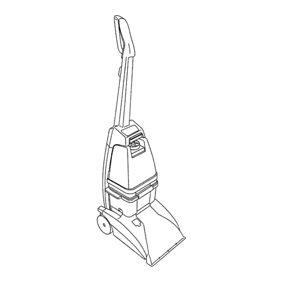
- Page 3 1. General Suction is directed to the floor through the clear nozzle and up into the recovery tank where the air The steam vac is a self contained domestic extractor and water are separated. A float prevents recovery tank from being overfitled. designed for deep cleaning of carpet and rugs.
- Page 4 Replaceable components of the tank assembly include the cap assembly, cap gasket and poppet valve. SPRING-._/_ WASHERT_ B Cap assembly VALVE SEAL'_t_ Fig. 3A VALVE STEM "'_ 1. Twist off to remove. (Fig. 2) The cupped end of the valve seal faces downward upon reassembly.
- Page 5 LATCH Fig. 8 Fig. 6 3. Remove lid assembly. (Fig. 9) The. handle i.q r_.nlaep.d a._ an a._._.mhlv The handle is replaced as an assembly. If the upper handle rod becomes dislodged during disassembly, reposition it with the large fin towards the front of the handle.
- Page 6 2. Carefully pry inward on rear panels of hood to release snaps. (Fig. 12) Fig. 15 Fig. 12 To reassemble hood. 1. Position two locating tabs in front corners into 1. Lift hood until it clears latches and push forward to mating boss on base and pivot hood down into remove.
- Page 7 Pumpis replacedas an assembly which includesthe M. Motor cover assembly quickconnectandtubing.(Fig. 18) MOTOR DISTRIBUTOR HOSE COVER ASSEMBLY ® Fig. 18 The quick connect is also available as a separate service item. L. Pump duct Fig. 20 The pump duct is held by the pump mounting screw.
- Page 8 The motorcoverassemblyconsistsof the recovery Handle release lever tank latchesanddistributor. The RH trunnion traps the handle release lever. Slide lever inward then up to remove. (Fig. 24) To remove distributor. Fig. 24 1. Push outward on distributor stem while pulling out and down on 'T' boss.
- Page 9 1. Disconnect l eadsat switch,insulatedterminaland 0. Handle cover groundscrew. 1. Release four snaps and lift cover off. (Fig. 2. Disconnect c ordfromcordclip in backof handle. 28 A & B) 3. Snapstrainreliefout of housing. Note: Uponreassembly,routecordas shownin Fig. 26. Also it is very important to reconnectground lead.
- Page 10 S. Reservoir assembly 1. Release two clips and remove from cradle in lower handle. (Fig. 30) The reservoir is replaced as an assembly which does not include tubing. Fig. 32 T. Motor The reservoir assembly can be inspected by removing the diaphragm valve and checking...
- Page 11 Note: Thefoam sealon the motorbaseis critical andmustbe replacedif damagedor missing. Positionthe foam per Fig. 33. Fig. 33 SEAL TANDPIPE Fig. 35 SEAL LOCATION 1. Remove 'E' clip and slide wheel shaft out Fig. 33 of housing. (Fig. 36) U. Motor seals MAIN BODY Two seals are positioned...
- Page 12 Hose assembly CONVERTER HOSE WAND VALVE UPHOLSTERY Serviceable components of the hose assembly B. Upholstery nozzle shown in the above diagram. Insert a screwdriver at the nozzle lock and pry upward A. Hose on the flange on the upholstery nozzle. Pull the nozzle off the wand.
- Page 13 IV. Troubleshooting check list - Steam Vac The following is a guide to aid in determining the origin of a problem for which these models could conceivably be brought in for service. PROBLEM POSSIBLE CAUSE POSSIBLE SOLUTION A. Motor 1. Unit not firmly plugged in.
- Page 14 IV.Troubleshooting checklist - SteamVac(cont'd) PROBLEM POSSIBLE CAUSE POSSIBLE SOLUTION D. Unit 1. Solution tank empty. Refill and check operation. won't 2. Poppet valve malfunctioning. Check and replace - located in bottom of solution tank. pump. (where 3. Solution tank opening clogged. Clean and check operation.
Need help?
Do you have a question about the F5835-900 and is the answer not in the manual?
Questions and answers