
Subscribe to Our Youtube Channel
Related Manuals for Agri-Fab 45-0491


Summary of Contents for Agri-Fab 45-0491
- Page 1 odel No. 45-0491 50" SNOW THROWER CAUTION'. ,, Safety Read Rules for ,, Assembly Safe Operation ,, Operation and Instructions ,, Maintenance Carefully ,, Parts PRINTED IN U.S.A. FORM NO. 42432 (08/21/12)
- Page 2 ACCESSORIES ............... SERVICE ANDADJUSTMENTS ........SAFETY RULES .............. STORAGE ..............TROUBLESHOOTING ........... FULLSIZEHARDWARE CHART ......... CARTON CONTENTS ............. REPAIR PARTS ILLUSTRATION ......22,24,26 ASSEMBLY ..............REPAIR PARTS LIST ........... 23,25,26 OPERATION ..............SLOPE GUIDE .............. MAINTENANCE ............PARTS ORDERING/SERVICE ....
- Page 3 Read and understand the operating instructions before using. Keep the area of operation clear of all persons, especially small children and pets. Thoroughly inspect the area to be cleared and remove all door mats, sleds, boards, wires and other foreign objects. Use extreme caution when operating on or crossing gravel surfaces.
- Page 4 ATTENTION:Thehardware bagsmaycontain someboltsandnutswhichdonotappear o nthispageorthefollowing page. T hoseboltsandnutswillnotbeneeded fortheassembly o fyoursnowthrower. SHOWN ACTUAL SIZE 43182 47630 48106 43661 43063 710-0890A j_-_-q _ ....43080 49933 43350 44326 46938 43682 44215 R19171616 43088 43081 43070 R19172410 43003 43082 47810 47572 47598 44695...
- Page 5 NOT SHOWN ACTUAL SIZE 731-0851A 46959 47134 43055 43343 25780 711-0332 1643-60 23727 43038 J JJ 47788 726-0178 HA23761 46963 IMPORTANT: Not all items supplied in the hardware bags will be needed for your particular tractor. Unneeded items may be discarded after you have completed assembly and checked operation of unit. DO NOT DISCARD the two spare shear bolts (F) and 5/16"...
- Page 6 Housing Assembly 11. ClutchIdlerAssembly 12. CableBracket ChuteCrankRodAssembly Support T ube, C rankRod 13. L.H.Hanger B racket WinchAssembly 14. R.H.Hanger B racket Anti-rotation B racket. 15. Pulley FrontPulley Frame Bracket ( 2) 16. Chute andControl C able Assembly RearPulley Frame Bracket (2) 17.
- Page 7 TOOLS REQUIRED FOR ASSEMBLY ATTACHING PARTS TO TRACTOR FRAME (2) 7/16" Wrenches STEP 1: (SEE FIGURE 1) (2) 1/2" Wrenches • Align the Winch and Bracket Assembly with the front (2) 9/16" Wrenches of the tractor frame and install two 3/8" x 1" carriage (2) 3/4"...
- Page 8 STEP3: (SEEFIGURE 3) STEP 5: (SEE FIGURE 5) • Install a hexheadshoulder b olt,a 3/8"washer a nda Remove the two screws in the right side of the plastic 3/8"flanged locknutintheR.H.andL.H.SidePlates. dash housing. install the cable clip onto the rocker switch wiring. Attach the switch mounting assembly and clip to the side of the plastic dash housing, using the two screws.
- Page 9 STEP 7: INSTALL HANGER BRACKETS AND SHOULDER BOLTSTO OUTSIDE OF FRAME REAR MOUNTED BATTERY ONLY • Mount the wire harness relay box in front of the STEP 9: (SEE FIGURE 7) solenoid on the right hand side of the gas tank, •...
- Page 10 THIS SECTION IS FOR TRACTORS WITH A STEP 13: (SEE FIGURE 11) MAN UAL ATTACHM ENT CLUTCH • Attach each rear pulley frame bracket to the inside of the clutch/idler assembly using two 5/16" x 3/4" hex if your tractor has an electric attachment clutch go to bolts, 5/16"...
- Page 11 STEP15: (SEEFIGURE 13) PIVOT LOCK PiN 1/8" HAiRPiN NYLON TiE Find the cable clip that is attached to the left side (use this hole) COTTER of the tractor frame underneath the footrest. Open the clip and remove the mower clutch cable. Do not L.H.
- Page 12 THIS SECTION IS FOR TRACTORS WITH AN STEP 20: (SEE FIGURE 18) ELECTRIC ATTACHMENT CLUTCH Attach each rear pulley frame bracket to the inside of the clutch/idler assembly using two 5/16" x 3/4" hex STEP 18: (SEE FIGURE 16) bolts, 5/16" washers and 5/16" nylock nuts. •...
- Page 13 STEP22: (SEEFIGURE 20) STEP 23: (SEE FIGURE 21) • Attach the clutch/idler assembly to the tractor frame. • Assemble the drive belt onto the engine pulley.You Hook the notched rear pulley frame brackets onto the may need to remove the belt from the large pulley on two shoulder bolts assembled to the outside of the the clutch/idler assembly in order to assemble it onto tractor frame.
- Page 14 STEP24: (SEEFIGURE 22) STEP 26: (SEE FIGURE 24) • Remove t henylon tie which fastens thechutecrank Attach the chute crank rod assembly brackets to rodtothecrankrodsupport t ube. the plastic bracket on the left side of the discharge Assemble t hecrankrodsupport t ubetothebracket housing.
- Page 15 STEP 27: (SEEFIGURE 25) ATTACHING SNOW THROWER TO TRACTOR • Coatthetopof theringaround thedischarge o pening withgeneral purpose grease. STEP 28: (SEE FIGURE 26) Place thedischarge c hute(facing forward) o ntothe Place the snow thrower on a flat, level surface. ring.Place theanti-rotation bracket o ntopofthechute Extend the auger belt out behind the snow thrower, flange, a ligning it withthe holes ontherighthandside leaving the belt assembled to the snow thrower pulleys.
- Page 16 STEP30: (SEEFIGURE 28) iNSTALLiNG THE AUGER BELT • Place theendofthewinch cableontotheliftlink. Place a 1/2"washer ontothelinkandinstall a 5/64" STEP 32: (SEE FIGURE 30) hairpin cotter. Start with the snow thrower lowered to the ground. Swing the idler arm over to the L.H. side of the tractor. HINT:Pushontheliftstopplateto rotate theliftlinkinto Place the auger belt around the rear V-pulley and betterposition to install t hewinch cable.
- Page 17 SETTING THE AUGER BELT TENSION ATTACH REFLECTORS TO REAR FENDER STEP 33: (SEE FIGURE 31) STEP 34: (SEE FIGURE 32) • Pull the right side tensioning chain until the end of the If your tractor is not equipped with rear reflectors, spring is pulled into the hole in the side of the Clutch/ assemble the supplied rear reflectors to the rear fender.
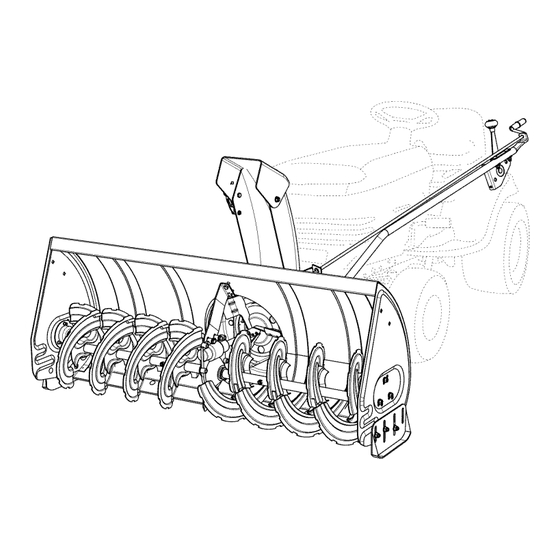
- Page 18 KNOW YOU R SNOW TH ROWER Read this owner's manual and safety rules before operating your snow thrower. Compare the illustration below with your snow thrower to familiarize yourself with the various controls and their locations. CHUTE TiLT HANDLE TOGGLE SWITCH UPPER CHUTE LOWER CHUTE SKiD SHOE...
- Page 19 RAISING AND LOWERING In extremely deep snow, raise the snow thrower up to the transport position to remove the top layer of • Use the toggle switch attached to the side of the tractor's dash to raise or lower the snow thrower. The snow.
- Page 20 CAUTION: Before servicing oradjusting SHEAR BOLT AND thesnow thrower, shut o fftheengine, r emove HEX LOCK NUT thespark plug wire(s), settheparking b rake andremove t hekey from thetractor i gnition. REPLACING AUGER BELT • Disengage the tractor's attachment clutch. Lower the snow thrower to the ground. Release the spring tension from the auger belt idler arm on the bottom of the clutch/idler assembly.
- Page 21 STORAGE RECOMMENDATIONS PARTS TO REMOVE AT END OF SEASON • Lower the snow thrower to the ground. Remove the snow thrower from the tractor. Remove the clutch/idler assembly. (The two hanger Clean the snow thrower thoroughly. Wash off any salt brackets and the two shoulder bolts may be left deposit which may have dried on the thrower and attached to the tractor frame.)
- Page 22 REPAIR PARTS FOR MODEL 45-0491 50" SNOW THROWER 18 j...
- Page 23 REPAIR PARTS FOR MODEL 45-0491 50" SNOW THROWER PART NO DESCRIPTION PART NO DESCRIPTION 731-0921 Chute, Upper 44950 Carriage Bolt, 1/4-20 x 3/4" 731-1300C Chute, Lower 47630 Bolt, Self-Tap 5/16"x 3/4" 731-1379A Hex Bolt, 5/16-18 x 3/4" Chute Adapter 43182 731-0851A Hex Bolt, 5/16-18 x 1-1/4"...
- Page 24 REPAIR PARTS FOR MODEL 45-0491 50" SNOW THROWER 41 40 39 43 • 65" -j J 49 53/_ ® 9 56 3637 12 29 6,// 62 /...
- Page 25 REPAIR PARTS FOR MODEL 45=0491 50" SNOW THROWER PART NO DESCRIPTION PART NO DESCRIPTION 67620 Bracket, Chute Crank Lift Shaft Assembly 24393 710-0865 Hex Bolt, 1/2-13 x 1" 741-0475 Bushing, 3/8" Plastic 710-0367 Hex Bolt, 5/8-11 x 1-1/2" 703-2735A Bracket, Chute Crank 711-0332 Pin, Bracket Lift 720-0201A...
- Page 26 REPAIR PARTS FOR MODEL 45-0491 50" SNOW THROWER PART NO DESCRIPTION 63762 Idler Bracket Assembly 43015 Hex Nut, 3/8-16 46981 Pulley, V Type 9" 43082 Nut, Hex Lock, 3/8-16 46982 Pulley, VType 5-1/2" 738-0680 Shaft 750-0456 Spacer 750-0660 Spacer 43003 Lock Washer, 3/8"...
- Page 27 SIGHT AND HOLD THiS LEVEL WiTH A VERTICAL TREE "O ¢1 _'5 E _" • "_ • "o o CAUTION: NOT OPERATE YOUR TRACTOR SNOW THROWER ON A SLOPE IN EXCESS OF 10 DEGREES. BE SURE OF YOUR TRACTOR'S TOWING BRAKING CAPABILITIES BEFORE OPERATING ON A SLOPE.
- Page 28 REPAIR PARTS Agri-Fab, Inc. 809 South Hamilton Sullivan, IL. 61951 217-728-8388 www.agri-fab.com © 2012 Agri-Fab, Inc.
Need help?
Do you have a question about the 45-0491 and is the answer not in the manual?
Questions and answers