Table of Contents

Subscribe to Our Youtube Channel
Related Manuals for Agri-Fab LST42E


Summary of Contents for Agri-Fab LST42E
- Page 1 ™ OWNERS MANUAL Model No. LST42E 42" SNOW THROWER • Safety • Assembly • Operation CAUTION: • Maintenance Read Rules for Safe • Parts Operation and Instructions Carefully the fastest way to purchase parts www.speedepart.com PRINTED IN U.S.A. FORM NO. 41650 (9/11/14)
-
Page 2: Table Of Contents
TABLE OF CONTENTS SAFETY RULES ................................... 3 FULL SIZE HARDWARE CHART ............................4 CARTON CONTENTS ................................6 ASSEMBLY ................................... 7 OPERATION ..................................25 MAINTENANCE ................................. 26 SERVICE AND ADJUSTMENTS ............................27 STORAGE ..................................28 TROUBLESHOOTING ................................ 28 REPAIR PARTS ILLUSTRATION ..........................30,32,34 REPAIR PARTS LIST.............................. -
Page 3: Safety Rules
SAFETY Read and understand the operating instructions before using. Keep the area of operation clear of all persons, especially small children and pets. Thoroughly inspect the area to be cleared and remove all door mats, sleds, boards, wires and other foreign objects. Use extreme caution when operating on or crossing gravel surfaces. Never direct discharge at bystanders or allow anyone in front of the snow thrower. 184045 199682 199683 Do not place hands near rotating parts. Keep clear of the Do not place feet near rotating parts. discharge opening at all times. • Never allow children to operate the equipment. • Take all possible precautions when leaving the unit • Never allow adults to operate the equipment without unattended. Disengage the attachment clutch lever or proper instruction. switch, lower the snow thrower, shift into neutral, set • Disengage all clutches and shift into neutral before the parking brake, stop the engine and remove the key. -
Page 4: Full Size Hardware Chart
HARDWARE PACKAGE CONTENTS SHOWN ACTUAL SIZE 43182 47630 43661 43063 47631 43084 43080 48106 44326 43682 47598 46938 43350 44215 46584 43003 43088 43081 47572 47810 49933 44695 47605, 43070 43082 42849 R19172410 NOT SHOWN ACTUAL SIZE 46959 27809 27810 42848 HA3090 43343... - Page 5 REF. QTY. DESCRIPTION REF. QTY. DESCRIPTION Hex Bolt, 3/8" x 3-1/4" Washer, 3/8" Hex Bolt, 5/16" x 1-3/4" Bowed Washer Hex Bolt, 5/16" x 1" Flanged Nut, 1/4" Hex Bolt, 5/16" x 3/4" Flanged Nut, 5/16" Hex Bolt, 1/4" x 1" Flanged Nut, 3/8"...
-
Page 6: Carton Contents
CARTON CONTENTS Housing Assembly V-Belt, Drive 56" (#48138) Lift Handle and Cable V-Belt, Drive 55" (#46989) Chute Crank Rod Assembly 15. V-Belt, Auger (Attached to Housing Assembly) Support Tube, Crank Rod 16. L.H. Hanger Bracket (Outside Mounting) Engagement Rod (Not used on some models) 17. R.H. Hanger Bracket (Outside Mounting) Cable Bracket 18. L.H. Hanger Bracket (Inside Mounting) Engine Pulley Keeper (Not used on some models) 19. R.H. Hanger Bracket (Inside Mounting) Chute and Control Cable Assembly Left Hand Side Plate Clutch Idler Assembly Right Hand Side Plate 10. Rear Pulley Frame Bracket (2) Pulley 11. Anti-rotation Bracket. -
Page 7: Assembly
ASSEMBLY TOOLS REQUIRED FOR ASSEMBLY IDENTIFY YOU TRACTOR (2) 7/16" Wrenches STEP 1: (SEE FIGURE 1) (2) 1/2" Wrenches • Look under the front of your tractor. If there is a single (2) 9/16" Wrenches mower deck suspension bracket located underneath (2) 3/4" Wrenches the middle of the front axle, continue on to step (1) Screw Driver 2. If your tractor does not have a mower deck (1) Knife suspension bracket underneath the middle of the front axle, skip to step 21 on page 13 for tractors... - Page 8 INSTALL SIDE PLATES INSTALL HANGER BRACKETS AND SHOULDER BOLTS TO OUTSIDE OF FRAME STEP 3: (SEE FIGURE 3) • Fasten the R.H. Side Plate (bend facing out) to the STEP 5: (SEE FIGURE 5) front three holes in the tractor frame using three 3/8" • Remove the bolt, if present, in the hole directly behind x 1" carriage bolts, three 1/2" washers (see note) and the brake rod on the left side of the tractor frame. three 3/8" flange nuts. For the rear hole, use a 5/16" x • Attach the L.H. Hanger Bracket (tube facing out) to the 1" carriage bolt, a 1/2" washer and a 5/16" nylock nut.
- Page 9 THIS SECTION IS FOR TRACTORS WITH A STEP 9: (SEE FIGURE 9) • Attach each rear pulley frame bracket to the inside MANUAL ATTACHMENT CLUTCH of the clutch frame using two 5/16" x 3/4" hex bolts, If your tractor has an electric attachment clutch go to 5/16" washers and 5/16" nylock nuts. step 14 on page 11. • Attach each front pulley frame bracket to the inside of the clutch frame using two 5/16" x 1" hex bolts, four STEP 7: (SEE FIGURE 7) 5/16" washers and two 5/16" nylock nuts.
- Page 10 STEP 11: (SEE FIGURE 11) 1/8" HAIRPIN PIVOT LOCK PIN NYLON TIE • Find the cable clip that is attached to the left side COTTER (use this hole) of the tractor frame underneath the footrest. Open the clip and remove the mower clutch cable. Do not L.H. HANGER SHOULDER remove the clip from the tractor frame. The cable BRACKET BOLT reattaches to the clip when using the mower deck. • Move the attachment clutch lever on the dash panel to the disengaged position. • Place the clutch/idler assembly on the floor on the left side of the tractor. • Attach the tractor's mower clutch cable to the cable MOWER bracket on the clutch/idler assembly. Secure the cable CLUTCH...
- Page 11 THIS SECTION IS FOR TRACTORS WITH AN STEP 16: (SEE FIGURE 16) • Attach each rear pulley frame bracket to the inside of ELECTRIC ATTACHMENT CLUTCH the clutch/idler assembly using two 5/16" x 3/4" hex bolts, 5/16" washers and 5/16" nylock nuts. STEP 14: (SEE FIGURE 14) • Attach each front pulley frame bracket to the inside • Turn the clutch idler assembly upside down. of the clutch/idler assembly using two 5/16" x 1" hex • Hook the spring onto the end of the bolt that extends bolts, four 5/16" washers and two 5/16" nylock nuts. through the nut on the bottom of the upper idler arm. Install a 3/8" hex lock nut onto the bolt, leaving enough space for the spring to pivot. 5/16"...
- Page 12 STEP 18: (SEE FIGURE 17) STEP 20: (SEE FIGURE 19) • Turn the clutch/idler assembly right side up. • Assemble the drive belt onto the engine pulley. You • Slightly loosen the hex bolt next to the flat idler pulley. may need to remove the belt from the large pulley on Install the drive belt down between the hex bolt and the the clutch/idler assembly in order to assemble it onto flat idler pulley with the flat side of the belt against the the engine pulley. When re-assembling the belt onto pulley. Retighten the hex bolt. the large pulley, be sure the belt is between the large • Loop the belt around the large v-pulley, placing it pulley and the hex bolt next to it. between the v-pulley and the hex bolt next to the pulley. • Place tension on the belt by pulling the left side tensioning chain out as far as the 3/32" hairpin cotter that was installed in the chain in step 15 will allow. HEX BOLTS FLAT IDLER Secure the chain in this position by inserting a 1/8"...
- Page 13 INSTRUCTIONS FOR TRACTORS WITH DUAL STEP 23: (SEE FIGURE 22) FRONT DECK SUSPENSION BRACKETS • Remove any bolts found in the holes shown. REMOVE BOLTS FASTEN SIDE PLATES TO TRACTOR IF PRESENT f your tractor resembles figure 20, start with step 21. If your tractor resembles figure 22, start with step 23. STEP 21: (SEE FIGURE 20) • Remove bolts from front three holes shown. • If a bolt is present in the fourth hole, replace it with a 5/16" x 1" carriage bolt without a nut. The bracket FRONT SUSPENSION fastened to inside of frame must remain in place. BRACKET REPLACE BOLT FIGURE 22...
- Page 14 INSTALLING HANGER BRACKETS INSTALLING SHOULDER BOLTS For better clearance, lower the tractor's suspension arms using the attachment lift lever. STEP 27: (SEE FIGURE 27) • Remove the bolt, washer and nut which fasten the sway bar bracket to the L.H. side of the tractor frame. STEP 26: (SEE FIGURE 25 or 26) Replace with a shoulder bolt and a 3/8" flanged nut. On Tractors With Foot Rest Brackets Bolt goes on inside of frame. • Remove the bolt and nut that fasten the L.H. and R.H. foot rest brackets to the frame. • Attach the L.H. Hanger Bracket (marked "L") to the inside of the tractor frame using two 3/8" x 1" carriage bolts and 3/8" flanged nuts. Bolt heads go on inside of tractor frame. Repeat for the R.H. side. BOLT REMOVED FROM THIS HOLE 3/8"...
- Page 15 INSTALLING CLUTCH/IDLER ASSEMBLY • Insert a tensioning chain through the hole shown and attach the end link to the spring on the lower idler arm. This section covers the installation of the Clutch/Idler assembly to tractors with attachment clutches that are either rod operated (p. 15), cable operated (p. 17) or 5/16" x 3/4" HEX BOLT electric (p. 19). Use the appropriate instructions for your 5/16" tractor. WASHER ROD OPERATED MANUAL ATTACHMENT CLUTCH STEP 29: (SEE FIGURE 29) • Move the attachment clutch lever on the dash panel to the disengaged (down) position.
- Page 16 STEP 32: (SEE FIGURE 32) NEW ENGINE PULLEY KEEPER WITH • Be sure to lift up the front end of the engagement rod ORIGINAL BOLT, NUT AND WASHER as shown when performing the next operation. You can temporarily support the rod using a rubber band tied to the engine pulley keeper. • Attach the clutch/idler assembly to the tractor frame TRUNNION as follows. Hook the assembly's notched rear pulley frame brackets onto the two shoulder bolts you STOP BOLT assembled to the inside of the tractor frame. Lift the front of the assembly and attach it to the R.H. and L.H. hanger brackets using two pivot lock pins and 1/8" hairpin cotters. IDLER ARM 3/8" THIN PIVOT LOCK PIN (MM) WASHER (use second hole) 5/64"...
- Page 17 CABLE OPERATED MANUAL ATTACHMENT CLUTCH STEP 37: (SEE FIGURE 37) • Two different length drive belts are included with STEP 35: (SEE FIGURE 35) your snow thrower. Tractors with manual attachment • Assemble the cable bracket to inner part of the double clutches and dual front deck suspension brackets use holes in the clutch/idler assembly using two 5/16" the 55" drive belt with #46989 printed on the outside x 3/4" carriage bolts and 5/16" nylock nuts. If your of the belt. DO NOT USE the other belt. tractor has a 42" mower deck, use the two front holes • Slightly loosen the hex bolt next to the flat idler pulley. in the cable bracket. If your tractor has a 46" mower Install the drive belt down between the hex bolt and the deck, use the two rear holes. flat idler pulley with the flat side of the belt against the pulley. Retighten the hex bolt. 5/16" x 3/4" • Loop the belt around the large v-pulley, placing it CARRIAGE BOLT between the v-pulley and the hex bolt next to the pulley.
- Page 18 STEP 38: (SEE FIGURE 38) NEW ENGINE PULLEY KEEPER WITH • Move the attachment clutch lever on the dash panel to ORIGINAL BOLT, NUT AND WASHER the disengaged (down) position. • Place the clutch/idler assembly on the floor on the right PIVOT LOCK PIN side of the tractor. (use second hole) • Attach the tractor's clutch cable to the cable bracket. Secure the cable housing guide (groove down) to the 1/8" HAIRPIN COTTER cable bracket using the original collar and a 5/64" hair cotter pin.
- Page 19 ELECTRIC ATTACHMENT CLUTCHES STEP 43: (SEE FIGURE 43) • Attach the two rear pulley frame brackets to the inside of the clutch/idler assembly using two 5/16" x 1" hex STEP 41: (SEE FIGURE 41) bolts, eight 5/16" washers and two 5/16" nylock nuts • Turn the clutch idler assembly upside down. for each bracket. • Hook the spring (onto the end of the bolt that extends • Attach the two front pulley frame brackets to the inside through the nut on the bottom of the upper idler arm. of the clutch/idler assembly using two 5/16" x 3/4" hex Install a 3/8" hex lock nut onto the bolt, leaving enough bolts, 5/16" washers and 5/16" nylock nuts for each space for the spring to pivot. bracket. SPRING 5/16" x 3/4" HEX BOLT 5/16"...
- Page 20 STEP 45: (SEE FIGURE 44) STEP 47: (SEE FIGURE 46) • Turn the clutch/idler assembly right side up. • Assemble the drive belt onto the engine pulley and • Slightly loosen the hex bolt next to the flat idler pulley. then onto the large pulley on top of the clutch/idler Install the drive belt down between the hex bolt and the assembly. The belt must be placed to the inside of flat idler pulley with the flat side of the belt against the the idler pulley and the keeper bolt located beside the pulley. Retighten the hex bolt. large pulley. • Loop the belt around the large v-pulley, placing it • Place tension on the belt by pulling the left side between the v-pulley and the hex bolt next to the pulley. tensioning chain out as far as the 3/32" hairpin cotter will allow. Secure the chain in this position by inserting a 1/8"...
- Page 21 ASSEMBLY OF THE SNOW THROWER STEP 50: (SEE FIGURE 49) • Tilt the snow thrower back down to the ground. STEP 48: (SEE FIGURE 47) • Remove the nylon tie which fastens the auger • Place the lift handle into the lift bracket on the right side drive belt to the discharge housing, leaving the belt of the snow thrower. Fasten the handle to the bracket assembled around the pulleys. using two 5/16" x 1-3/4" hex bolts and 5/16" Nylock • Remove the nylon tie which fastens the chute crank nuts. rod to the crank rod support tube. • Assemble the crank rod support tube to the bracket on the left side of the discharge housing using two 5/16" x 1-1/4" carriage bolts, and 5/16" Nylock nuts.
- Page 22 STEP 52: (SEE FIGURE 51) STEP 53: (SEE FIGURE 52) • Attach the chute crank rod assembly brackets to • Coat the top of the ring around the discharge opening the plastic bracket on the left side of the discharge with general purpose grease. housing. Align the chute crank bracket beneath the • Place the discharge chute (facing forward) onto the rod support bracket and assemble both to the plastic ring. Place the anti-rotation bracket on top of the chute bracket using two 5/16" x 1" carriage bolts, 5/16" flange, aligning it with the holes on the right hand washers and 5/16" Nylock nuts. Do not tighten yet. side of the flange. Attach the three chute spacers and chute keepers to the bottom of the flange using six 1/4" x 1" hex bolts, 1/4" flat washers and 1/4" flanged lock nuts. Tighten carefully so that the nuts are snug 5/16"...
- Page 23 ATTACHING SNOW THROWER TO TRACTOR STEP 57: (SEE FIGURE 56) • Push the lift handle down to increase slack in the belt. STEP 55: (SEE FIGURE 54) • Swing the lower idler arm over to the left side. • Place the snow thrower on a flat, level surface. • Place the auger belt around the rear pulley and • Extend the auger belt out behind the snow thrower, between the two pulleys on the idler arm. The "V" keeping the belt assembled to the snow thrower pulleys. side of the belt must be seated in the grooves of the • Roll the tractor up behind the snow thrower, centering V-pulleys. it between the snow thrower's mounting plates. • Raise the rear of the snow thrower by lifting up on the lift handle until the notches in the mounting plates LEFT SIDE align with the shoulder bolts in the tractor's side OF TRACTOR plates. Guide the bolts into the notches.
- Page 24 INSTALLING THE CLEVIS PINS ATTACH REFLECTORS TO REAR FENDER STEP 59: (SEE FIGURE 58) STEP 58: (REFER BACK TO FIGURE 54 ON PAGE 23) • If your tractor is not equipped with rear reflectors, • Lift the front of the snow blower to align the holes in assemble the supplied rear reflectors to the rear the mounting plates and the side plates. Insert two fender. Place the reflectors as close to the bottom of 1/2" x 7/8" clevis pins through the holes and secure the fender and as far apart as the shape of the fender them with the 1/8" hairpin cotters.
-
Page 25: Operation
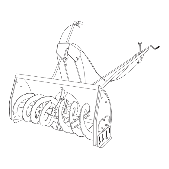
OPERATION KNOW YOUR SNOW THROWER Read this owner's manual and safety rules before operating your snow thrower. Compare the illustration below with your snow thrower to familiarize yourself with the various controls and their locations. LIFT RELEASE TRIGGER CHUTE TILT HANDLE LIFT HANDLE CRANK ROD UPPER CHUTE LOWER CHUTE SKID SHOE SCRAPER PLATE SPIRAL AUGERS, R.H. & L.H. UPPER AND LOWER DISCHARGE CHUTE Controls CHUTE TILT HANDLE Pivots the Upper Chute up or down to control the angle and distance of discharge. -
Page 26: Maintenance
RAISING AND LOWERING • In extremely deep snow, raise the snow thrower from the ground to remove the top layer and drive forward • To raise, push down on the lift handle until the snow only until the tractors front tires reach the uncleared thrower locks in the raised transport position. bottom layer of snow. Depress the tractor's clutch- • To lower, push down slightly on the lift handle and pull brake pedal and allow the spiral auger to clear the the trigger. With the trigger pulled, slowly lower the snow. Reverse the tractor and lower the snow thrower snow thrower until it reaches the ground. -
Page 27: Service And Adjustments
SERVICE AND ADJUSTMENTS LIFT RELEASE CABLE ADJUSTMENT CAUTION : Before servicing or adjusting the snow thrower, shut off the engine, remove • If the lift rod does not lock the snow thrower securely the spark plug wire(s), set the parking brake in the transport position, loosen the upper hex nut on and remove the key from the tractor ignition. the lift bracket a few turns and tighten the lower hex nut. Refer to figure 48 on page 21. • If the lift rod fails to unlock completely to lower the REPLACING AUGER BELT snow thrower, loosen the lower hex nut on the lift • Disengage the tractor's attachment clutch. -
Page 28: Storage
STORAGE PARTS TO REMOVE AT END OF SEASON STORAGE RECOMMENDATIONS • Lower the snow thrower to the ground. • Remove the clutch/idler assembly. (The two hanger • Remove the snow thrower from the tractor. brackets and the two shoulder bolts may be left attached to the tractor frame.) • Clean the snow thrower thoroughly. Wash off any salt • Remove the drive belt from the engine pulley. deposit which may have dried on the thrower and • If you replaced the engine pulley keeper on a manual housing. • Any bare metal that has become exposed should be attachment clutch tractor, reinstall the tractor's original painted or coated with a light oil to prevent rust. engine pulley keeper. See figure 33 on page 16 or figure 39 on page 18. - Page 29 NOTES...
- Page 30 REPAIR PARTS FOR MODEL LST42E 42" SNOW THROWER 40,59 40,59...
-
Page 31: Washer
REPAIR PARTS FOR MODEL LST42E 42" SNOW THROWER PART NO DESCRIPTION PART NO DESCRIPTION 42716 Flange, Bearing 27458 Flange, Bearing 67629 Housing Assembly 43064 Hex Lock Nut, 1/4-20 x 20 71464 Gear Assembly 27502 Bracket, Idler 47026 Pulley, V Type 49933 Shoulder Bolt, Round Head 67632 Impeller Assembly 65367 Hanger Bracket Assembly, L.H. - Page 32 REPAIR PARTS FOR MODEL LST42E 42" SNOW THROWER...
-
Page 33: Washer
REPAIR PARTS FOR MODEL LST42E 42" SNOW THROWER PART NO QTY DESCRIPTION PART NO QTY DESCRIPTION 64637 Lift Shaft Assembly 49916 Tube, Lift Handle 41616 Hex Bolt, 1/2-13 x 1" 49912 Trigger and Lift Cable Assembly 41614 Hex Bolt, 5/8-11 x 1-1/2" 43070 Washer, 3/8" 42842 Pin, Clevis 1/2" x 78"... - Page 34 REPAIR PARTS FOR MODEL LST42E 42" SNOW THROWER PART NO QTY DESCRIPTION 24286 Spacer, Pivot 63762 Idler Bracket Assembly 43015 Hex Nut, 3/8-16 46981 Pulley, V Type 9" 43082 Nut, Hex Lock, 3/8-16 46982 Pulley, V Type 5-1/2" 27582 Shaft 42830 Spacer 42831 Spacer 43003 Lock Washer, 3/8"...
-
Page 35: Slope Guide
SLOPE GUIDE (Keep this sheet in a safe place for future reference.) Use this guide to determine if a slope is safe for the operation of your tractor and snow thrower. Refer also to the instructions in your vehicle owners manual. - Page 36 REPAIR PARTS Agri-Fab, Inc. 809 South Hamilton Sullivan, IL. 61951 217-728-8388 www.agri-fab.com This document (or manual) is protected under the U.S. Copyright Laws and the copyright laws of foreign countries, pursuant to the Universal Copyright Convention and the Berne convention. No part of this document may be reproduced or transmitted in any form or by any means, electronic or mechanical, including photocopying or recording, or by any information storage or retrieval system, without the express written permission of Agri-Fab, Inc. Unauthorized uses and/or reproductions of this manual will subject such unauthorized user to civil and criminal penalties as provided by the United States Copyright Laws. © 2003 Agri-Fab, Inc.
Need help?
Do you have a question about the LST42E and is the answer not in the manual?
Questions and answers