
Related Manuals for Agri-Fab LST 42


Summary of Contents for Agri-Fab LST 42
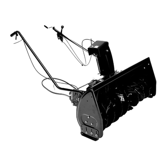
- Page 1 OWNERS MANUAL Model No. LST 42 42" SNOW THROWER • Safety CAUTION: Read Rules for • Assembly Safe Operation • Operation and Instructions • Maintenance Carefully • Parts PRINTED IN U.S.A. FORM NO. 48737 (10/02)
-
Page 2: Table Of Contents
TABLE OF CONTENTS SAFETY RULES ................................... 3 FULL SIZE HARDWARE CHART ............................4 CARTON CONTENTS ................................. 5 ASSEMBLY INSTRUCTIONS .............................. 6 OPERATION ..................................18 MAINTENANCE ................................. 19 SERVICE AND ADJUSTMENTS ............................20 STORAGE ..................................21 TROUBLESHOOTING ............................... 21 REPAIR PARTS ................................22 SLOPE GUIDE ................................... - Page 3 SAFETY Any power equipment can cause injury if operated improperly or if the user does not understand how to operate the equipment. Exercise caution at all times, when using power equipment. • Read this owner's manual carefully and know how •...
- Page 4 HARDWARE PACKAGE CONTENTS SHOWN ACTUAL SIZE SPARE PARTS BAG Store these two bolts and nuts in a safe place until needed. (See page 20.) NOT SHOWN ACTUAL SIZE REF. QTY. DESCRIPTION REF. QTY. DESCRIPTION Hex Lock Nut, 1/4" Hex Bolt, 3/8" x 1" Whizlock Nut, 5/16"...
-
Page 5: Carton Contents
ASSEMBLY CARTON CONTENTS Right Hand Side Plate (Stamped "R") Support Tube, Crank Rod Left Hand Side Plate (Stamped "L") 10. Lift Handle Tube and Cable 11. Clutch Idler Assembly Anti-rotation Bracket Engagement Rod 12. Cable Bracket Housing Assembly Engine Pulley Keeper Left Hand Hanger Bracket (Stamped "L") 14. - Page 6 ASSEMBLY OF SIDE PLATES TO TRACTOR TOOLS REQUIRED FOR ASSEMBLY Right hand (R.H.) and left hand (L.H.) side of the tractor are determined from the operators position while seated 7/16" Wrenches on the tractor. 1/2" Wrenches 9/16" Wrenches TRACTORS WITH FRAME MOUNTED FRONT 3/4"...
- Page 7 2. Attach the R.H. Side Plate (marked "R") to the right 5. Assemble a shoulder bolt, a 3/8" lock washer and a side of the tractor frame. For the front hole use a 3/8" 3/8" hex lock nut to the bottom hole in each side x 1"...
- Page 8 INSTALLING HANGER BRACKETS INSTALLING SHOULDER BOLTS For better clearance, lower the tractor's suspension arms using the attachment lift lever. All Tractors 1. Remove the bolt, washer and nut which fasten the sway bar bracket to the L.H. side of the tractor On Tractors With Foot Rest Brackets (Figure 7) frame.
- Page 9 INSTALLING CLUTCH/IDLER ASSEMBLY 1/8" HAIRPIN COTTER This section covers the installation of the Clutch/Idler PIVOT LOCK PIN assembly to tractors with attachment clutches that are either rod operated (p. 9), cable operated (p. 10) or ENGAGEMENT electric (p. 12). Use the appropriate instructions for your tractor.
- Page 10 CABLE OPERATED ATTACHMENT CLUTCHES 10. Assemble the short "V" belt onto the engine pulley and then onto the large pulley on top of the clutch/ 1. Assemble the cable bracket to the clutch/idler idler assembly. The belt must be placed to the assembly using two 5/16"...
- Page 11 6. Remove the engine pulley keeper from the side of 8. Assemble the short "V" belt onto the engine pulley the tractor frame by removing the washer and nut and then onto the large pulley on top of the clutch/ that secure the keeper.
- Page 12 5. Attach the clutch/idler assembly to the tractor frame ELECTRIC ATTACHMENT CLUTCHES by sliding the notched rear arms of the assembly 1. Turn the clutch/idler assembly upside down and onto the two shoulder bolts placed on the inside of place the extra tensioning chain through the left the tractor frame.
- Page 13 6. Assemble the short "V" belt onto the engine pulley ASSEMBLY OF THE SNOW THROWER and then onto the large pulley on top of the clutch/ idler assembly. The belt must be placed to the 1. Place the lift handle into the lift bracket on the right inside of the engine pulley keeper, the idler pulley side of the snow thrower.
- Page 14 3. Tilt the snow thrower back down to the ground. 5/16" x 1" CHUTE CRANK CARRIAGE BOLT BRACKET 4. Remove the nylon tie which fastens the auger drive belt to the discharge housing, leaving the belt assembled around the pulleys. CHUTE 5.
- Page 15 ATTACHING SNOW THROWER TO TRACTOR INSTALLING THE AUGER BELT 7. The auger belt comes preassembled to the pulleys on the snow thrower housing. Make sure the belt passes over the top of the auger pulley and then twists 1/4 turn to pass underneath each side idler NOTE: An dditional person's help may be required to pulley.
- Page 16 INSTALLING THE ATTACHMENT PIN CHECKLIST 11. Lift the front of the snow blower to align the holes Before you operate your snow thrower, please in the mounting plates and the side plates. From review the following checklist to help ensure that the left side of the tractor install the attachment pin you will obtain the best performance from your through the holes, securing it with the 1/8"...
-
Page 17: Operation
OPERATION KNOW YOUR SNOW THROWER Read this owner's manual and safety rules before operating your snow thrower. Compare the illustration below with your snow thrower to familiarize yourself with the various controls and their locations. LIFT RELEASE TRIGGER CHUTE TILT HANDLE LIFT HANDLE CRANK ROD UPPER CHUTE... -
Page 18: Maintenance
8. In extremely deep snow, raise the snow thrower RAISING AND LOWERING from the ground to remove the top layer and drive 3. To raise, push down on the lift handle until the forward only until the tractors front tires reach the snow thrower locks in the raised transport position. -
Page 19: Service And Adjustments
SERVICE AND ADJUSTMENTS LIFT RELEASE CABLE ADJUSTMENT CAUTION : Before servicing or adjusting 1. If the lift rod does not lock the snow thrower the snow thrower, shut off the engine, securely in the transport position, loosen the upper remove the spark plug wire(s), set the hex nut on the lift bracket a few turns and tighten parking brake and remove the key from the lower hex nut. -
Page 20: Storage
STORAGE PARTS TO REMOVE AT END OF SEASON STORAGE RECOMMENDATIONS 1. Remove the drive belt from the engine pulley. 1. Lower the snow thrower to the ground. 2. Remove the clutch/idler assembly. (The two hanger 2. Remove the snow thrower from the tractor. brackets and the two shoulder bolts may be left 3. - Page 21 NOTES...
-
Page 22: Repair Parts
PARTS REPAIR PARTS FOR MODEL LST 42 - 42" SNOW THROWER... - Page 23 REPAIR PARTS FOR MODEL LST 42 - 42" SNOW THROWER REF. PART QTY. DESCRIPTION REF. PART QTY. DESCRIPTION 05931 Housing, Bearing 741-0919 Bearing, Ball 63562 Housing Assembly 08253B Housing, Bearing 618-0616A Gear Assembly 15296A Housing, Open Bearing 63579 Chute Crank Rod Assembly...
- Page 24 REPAIR PARTS FOR MODEL LST 42 - 42" SNOW THROWER...
- Page 25 REPAIR PARTS FOR MODEL LST 42 - 42" SNOW THROWER REF. PART QTY. DESCRIPTION REF. PART QTY. DESCRIPTION 63764 Lift Shaft Assembly 703-2735A Bracket, Chute Crank 720-0201A Knob, Crank 710-0865 Hex Bolt, 1/2-13 x 1" 710-0367 Hex Bolt, 5/8-11 x 1-1/4"...
-
Page 27: Slope Guide
SLOPE GUIDE (Keep this sheet in a safe place for future reference.) Use this guide to determine if a slope is safe for the operation of your tractor and snow thrower. Refer also to the instructions in your vehicle owners manual. - Page 28 REPAIR PARTS Agri-Fab, Inc. 303 West Raymond Sullivan, IL. 61951 217-728-8388 www.agri-fab.com...
Need help?
Do you have a question about the LST 42 and is the answer not in the manual?
Questions and answers