Table of Contents
Advertisement
Quick Links
Download this manual
See also:
Cli Reference Manual
For Quick
Start Installation
Model 3231
Industrial Ethernet Extender with
LCD Interface
User Manual
Important
This is a Class A device and is intended for use in a light industrial environment. It is not intended nor approved for use in an industrial
or residential environment.
Sales Office:
+1 (301) 975-1000
Technical Support:
+1 (301) 975-1007
E-mail:
support@patton.com
WWW:
www.patton.com
Part Number: 07M3231-GS, Rev. B
Revised: February 16, 2012
Advertisement
Table of Contents

Related Manuals for Patton electronics 3231


Summary of Contents for Patton electronics 3231
-
Page 1: Model 3231
For Quick Start Installation Model 3231 Industrial Ethernet Extender with LCD Interface User Manual Important This is a Class A device and is intended for use in a light industrial environment. It is not intended nor approved for use in an industrial or residential environment. - Page 2 Patton Electronics Company, Inc. 7622 Rickenbacker Drive Gaithersburg, MD 20879 USA Tel: +1 (301) 975-1000 Fax: +1 (301) 869-9293 Support: +1 (301) 975-1007 Web: www.patton.com E-mail: support@patton.com Trademark Statement All other trademarks presented in this document are the property of their respective owners.
-
Page 3: Summary Table Of Contents
Summary Table of Contents General information ............................13 Initial Configuration ............................. 18 G.SHDSL Configuration and Status ......................28 Web Interface Configuration ........................34 System Management............................39 Contacting Patton for assistance ........................43 Compliance information ..........................46 Specifications ..............................49 RJ-11 non-shielded DSL port ........................ -
Page 4: Table Of Contents
Table of Contents Summary Table of Contents ........................... 3 Table of Contents ............................4 List of Figures ..............................7 List of Tables ..............................8 About this guide ............................. 9 Audience................................. 9 Structure................................. 9 Precautions ................................10 Safety when working with electricity .......................11 General observations ............................11... - Page 5 Model 3231 User Manual Table of Contents STP (Spanning Tree Protocol) ........................25 LEDs .................................26 Connecting to the Web GUI..........................26 Factory default IP address ..........................26 Modifying the IP address ..........................26 Connecting to the local IP network .........................27 Logging into the web management interface ....................27...
- Page 6 Model 3231 User Manual Table of Contents Safety ................................47 PSTN Regulatory ............................47 FCC Part 68 (ACTA) Statement ...........................47 Radio and TV Interference (FCC Part 15) ......................47 Industry Canada Notice ............................48 CE Declaration of Conformity ..........................48 Authorized European Representative ........................48 Specifications ..............................
-
Page 7: List Of Figures
List of Figures Model 3231 ................14 Model 3231 front panel . -
Page 8: List Of Tables
List of Tables General conventions ..............12 LCD Menu Keypad - Front Panel . -
Page 9: About This Guide
About this guide This guide describes installing and operating the Patton Electronics Model 3231 Industrial Ethernet Extender with LCD interface. Audience This guide is intended for the following users: • Operators • Installers • Maintenance technicians Structure This guide contains the following chapters and appendices: •... -
Page 10: Precautions
Model 3231 User Manual Precautions Notes, cautions, and warnings, which have the following meanings, are used throughout this guide to help you become aware of potential problems. are intended to prevent safety hazards that could result in per- sonal injury. -
Page 11: Safety When Working With Electricity
Model 3231 User Manual Safety when working with electricity • This device contains no user serviceable parts. The equipment shall be returned to Patton Electronics for repairs, or repaired by qualified service personnel. WARNING • AC Powered Units: The external power adaptor shall be a listed Limited Power Source. -
Page 12: Typographical Conventions Used In This Document
Model 3231 User Manual Typographical conventions used in this document This section describes the typographical conventions and terms used in this guide. General conventions The procedures described in this manual use the following text conventions: Table 1. General conventions Convention... -
Page 13: General Information
Chapter 1 General information Chapter contents Model 3231 Overview............................14 Features .................................14 Front Panel................................15 Menu keypad ..............................15 LEDs ................................16 Rear Panel ................................17 Application................................17... -
Page 14: Model 3231 Overview
Model 3231 User Manual 1 • General information Model 3231 Overview The Patton Electronics Model 3231 Industrial Ethernet Extender with LCD provides high speed 2-wire con- nectivity to ISPs, PTTs, and enterprise environments using Symmetrical High-data-rate Digital Subscriber Line (G.SHDSL) technology. -
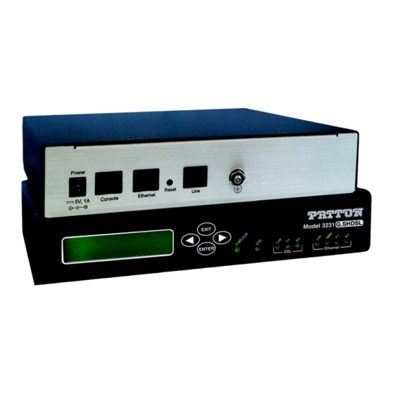
Page 15: Front Panel
Model 3231 User Manual 1 • General information Front Panel EXIT ENTER Ethernet Figure 2. Model 3231 front panel Menu keypad The Model 3231 contains an LCD menu and keypad, located on the front panel, for configuring the unit. The four keys on the menu keypad and their functions are: Table 2. -
Page 16: Leds
Model 3231 User Manual 1 • General information LEDs The Model 3231 contains nine LEDs on the front panel. All LEDs will blink twice when the unit is first pow- ered on. Table 3. Model 3231 LEDs Color Purpose PWR/ALM Green/Red •... -
Page 17: Rear Panel
Model 3231 User Manual 1 • General information Rear Panel o le E th e rn L in Model 3231 Power Reset 5V, 1A Console Ethernet Line Console Reset Ground RS-232 port button Power Ethernet G.SHDSL RJ-45 port RJ-11 port Figure 3. -
Page 18: Initial Configuration
Chapter 2 Initial Configuration Chapter contents Introduction ................................19 Power up the NTU ...............................19 AC power-up ..............................19 Power-up indication ............................19 Connecting the G.SHDSL port..........................19 Using the LCD Menu ............................20 G.SHDSL ...............................21 ................................21 CPE Config ..............................21 STP (Spanning Tree Protocol) ........................22 Syslog ................................22 Setting the unit as CO/CPE ..........................23... -
Page 19: Introduction
Model 3231 User Manual 2 • Initial Configuration Introduction The Model 3231 is configured through the LCD menu on the front panel. More advanced features may be configured through the Web GUI interface. The 3231 is Plug ‘n’ Play with the Model 3096RC G.SHDSL concentrator card or compatible G.SHDSL card. -
Page 20: Using The Lcd Menu
Model 3231 User Manual 2 • Initial Configuration o l e L i n Figure 4. Rear view of 3231 Using the LCD Menu The following sections are options in the top level menu on the LCD interface: • “G.SHDSL”... -
Page 21: G.shdsl
Model 3231 User Manual 2 • Initial Configuration G.SHDSL Table 4. G.SHDSL Menu Options Submenu Options Line Rate 192 kbps – 4608 kbps I-bits 0 – 7 Mode CO or CPE Annex A or B Transmit Gain -1.6 dB – 1.6 dB... -
Page 22: Stp (Spanning Tree Protocol)
Model 3231 User Manual 2 • Initial Configuration STP (Spanning Tree Protocol) Table 7. (STP) Spanning Tree Protocol Menu Options Submenu Options Enabled Enable or Disable STP Fwd Delay 4 – 30 seconds Hello Time 1 – 10 seconds Max Age 6 –... -
Page 23: Setting The Unit As Co/Cpe
Model 3231 User Manual 2 • Initial Configuration Setting the unit as CO/CPE Configuring the unit as CO To set the unit as CO: 1. From the top level menu on the LCD panel, use the Left and Right arrow keys to navigate to G.SHDSL, and press ENTER. -
Page 24: Using The Cli
Model 3231 User Manual 2 • Initial Configuration Using the CLI The Model 3231 may be configured through the CLI, although basic settings should be configured through the LCD menu on the unit. Note Use the LCD panel menu to primarily configure the unit. Refer to “Using... -
Page 25: G.shdsl
Model 3231 User Manual 2 • Initial Configuration G.SHDSL Table 9. G.SHDSL - CLI Commands Command Explanation gshdsl set dslrateTS <#timelots> Set the number of timeslots that each DSL frame will carry. The DSL data rate will be (64 kbps x #timeslots) + #ibits. -
Page 26: Leds
Model 3231 User Manual 2 • Initial Configuration LEDs Table 12. LEDs - CLI Commands Command Explanation console process led message <led> <mes- This command may be used to test the operation of sage> specific LEDs. It should not be used in normal opera- tion. -
Page 27: Connecting To The Local Ip Network
Model 3231 User Manual 2 • Initial Configuration Connecting to the local IP network Now you can connect the 3231 to your local IP network and access advanced configuration features from your PC using a standard web browser. Connect the 3231’s Ethernet port (green) to the same Ethernet segment as your PC (see figure 6). -
Page 28: G.shdsl Configuration And Status
Chapter 3 G.SHDSL Configuration and Status Chapter contents G.SHDSL Configuration ............................29 G.SHDSL Options ............................29 G.SHDSL Error Monitor Configuration.......................29 Viewing G.SHDSL Status .............................30 Run-Time Statistics ............................31 DSL Line Error Counters ..........................32 Local Interface Error Counters ........................32 Clearing Error Counters ..........................33... -
Page 29: G.shdsl Configuration
Model 3231 User Manual 3 • G.SHDSL Configuration and Status G.SHDSL Configuration Use the LCD panel to configure G.SHDSL. From the top level menu on the LCD panel, use the Left and Right arrows to navigate to G.SHDSL, and press ENTER. The following options are available in the G.SHDSL submenu:... -
Page 30: Viewing G.shdsl Status
Model 3231 User Manual 3 • G.SHDSL Configuration and Status The following shows the relationship of the DSL Error Monitor parameters: Interval #Total Startup Delay Interval #1 Interval #2 … Intervals Start Up Delay Interval Time (sec) Interval Time (sec) -
Page 31: Run-Time Statistics
Model 3231 User Manual 3 • G.SHDSL Configuration and Status Run-Time Statistics The Run-Time Statistics provide the state and relative health of the DSL link. The statistical parameters are described. Figure 8. DSL Run-time Statistics • G.SHDSL State: The link may be in one of these states, Deactivated, In Progress, or Normal Operation. -
Page 32: Dsl Line Error Counters
Model 3231 User Manual 3 • G.SHDSL Configuration and Status DSL Line Error Counters Five counters display how many Loss of Sync’s have occurred, CRC Errors, SEGD Errors, SEGA Errors, and Loss of Delineation. Loss of Sync and CRC Errors are the most commonly used statistics in normal performance evaluation. -
Page 33: Clearing Error Counters
Model 3231 User Manual 3 • G.SHDSL Configuration and Status Clearing Error Counters The error counters may be cleared in the Configuration web page or here in the Status web page. Select Clear All Counters and click on the Submit button. -
Page 34: Web Interface Configuration
Chapter 4 Web Interface Configuration Chapter contents Using the Web Interface............................35 SNMP ...................................36 STP (Spanning Tree Protocol) ..........................37 CPE Configuration ...............................38... -
Page 35: Using The Web Interface
Model 3231 User Manual 4 • Web Interface Configuration Using the Web Interface The Model 3231 provides a web interface for advanced configuration of: • “SNMP” on page 36 • “STP (Spanning Tree Protocol)” on page 37 • “CPE Configuration”... -
Page 36: Snmp
Model 3231 User Manual 4 • Web Interface Configuration SNMP You can use the Web GUI to configure SNMP. (See “Connecting to the Web GUI” on page 26). Note It is NOT reccommended that you configure basic options through the Web GUI. -
Page 37: Stp (Spanning Tree Protocol)
Model 3231 User Manual 4 • Web Interface Configuration STP (Spanning Tree Protocol) This section describes how to configure Spanning Tree Protocol through the web interface. To get to the STP configuration page in the Web GUI, click on Services Configuration > STP on the left navigation menu. -
Page 38: Cpe Configuration
Model 3231 User Manual 4 • Web Interface Configuration CPE Configuration This section describes how to configure the CPE unit through the web interface. To get to the CPE Configu- ration page in the Web GUI, click on G.SHDSL > CPE Configuration on the left navigation menu. -
Page 39: System Management
Chapter 5 System Management Chapter contents Reset for Factory Default............................40 Saving the configuration............................40 Backing up and restoring saved configurations ......................40 System Software Upgrade ............................41 Syslog Options in the LCD Menu.........................42... -
Page 40: Reset For Factory Default
Model 3231 User Manual 5 • System Management Reset for Factory Default To recover from a forgotten password, the user may reset the unit to its factory configuration. There is a Reset button located on the rear panel of the unit between the Ethernet and Line ports. -
Page 41: System Software Upgrade
Model 3231 User Manual 5 • System Management Click on the Backup/Restore Configuration hyperlink under the System Management menu. Figure 16. Backing up and reloaded saved configurations To back up the current saved configuration, click on Backup configuration in your computer link. You will have the option of either viewing the configuration file or saving it directly to your PC. -
Page 42: Syslog Options In The Lcd Menu
Model 3231 User Manual 5 • System Management Click on the Options link. This takes you to the Firmware Update Configuration page. Leave this set to Enabled. When enabled, the 3231 will detect if you are trying to do a software upgrade with an incorrect or improper software image. -
Page 43: Contacting Patton For Assistance
Chapter 6 Contacting Patton for assistance Chapter contents Introduction ................................44 Contact information..............................44 Patton support headquarters in the USA ......................44 Alternate Patton support for Europe, Middle East, and Africa (EMEA) ............44 Warranty Service and Returned Merchandise Authorizations (RMAs)..............44 Warranty coverage ............................44 Out-of-warranty service ..........................45 Returns for credit... -
Page 44: Introduction
Model 3231 User Manual 6 • Contacting Patton for assistance Introduction This chapter contains the following information: • “Contact information”—describes how to contact Patton technical support for assistance. • “Warranty Service and Returned Merchandise Authorizations (RMAs)”—contains information about the warranty and obtaining a return merchandise authorization (RMA). -
Page 45: Out-Of-Warranty Service
Model 3231 User Manual 6 • Contacting Patton for assistance Out-of-warranty service Patton services what we sell, no matter how you acquired it, including malfunctioning products that are no longer under warranty. Our products have a flat fee for repairs. Units damaged by lightning or other catastro- phes may require replacement. -
Page 46: A Compliance Information
Appendix A Compliance information Chapter contents Compliance ................................47 ................................47 Safety ................................47 PSTN Regulatory ............................47 FCC Part 68 (ACTA) Statement ...........................47 Radio and TV Interference (FCC Part 15) ......................47 Industry Canada Notice ............................48 CE Declaration of Conformity ..........................48 Authorized European Representative ........................48... -
Page 47: Compliance
Model 3231 User Manual A • Compliance information Compliance • FCC Part 15, Class A • EN55022, Class A • EN55024 Safety • UL 60950-1/CSA C22.2 N0. 60950-1 • IEC/EN60950-1 • AS/NZS 60950-1 PSTN Regulatory • FCC Part 68 •... -
Page 48: Industry Canada Notice
Model 3231 User Manual A • Compliance information able protection from such interference in a commercial installation. However, there is no guarantee that inter- ference will not occur in a particular installation. If the equipment causes interference to radio or television... - Page 49 Appendix B Specifications Chapter contents General characteristics ............................50 G.SHDSL characteristics ............................50 Ethernet ................................50 Protocol support..............................50 Management .................................51 10Base-T/100Base-TX interface ..........................51 Serial connector ..............................51 Diagnostics................................51 Status LEDs................................51 Power/Alarm ..............................51 ................................51 DSL Link ................................51 DSL Tx ................................51 DSL Rx ................................51 Ethernet Link ..............................51 Ethernet 100M ...............................52...
-
Page 50: B Specifications
Model 3231 User Manual B • Specifications General characteristics • Compact low-cost Plug ‘n’ Play NTU • 10/100 Ethernet port • Unlimited host support • Comprehensive hardware diagnostics, independent of operating system, easy maintenance and effortless installation • Built-in web configuration •... -
Page 51: Management
Model 3231 User Manual B • Specifications Management • Web-based configuration via embedded web server • CLI menu for configuration, management, and diagnostics • Local (VT-100 or Telnet) • Console port set at 9600 bps, 8 bits, no parity, 1 stop bit, no flow control 10Base-T/100Base-TX interface The Ethernet port is a shielded RJ-45 jack, autonegotiate, full- or half-duplex . -
Page 52: Ethernet 100M
Model 3231 User Manual B • Specifications Ethernet 100M The Ethernet 100M LED glows green when the Ethernet link negotiates to 100 Mbps. This LED is off when the Ethernet link negotiates to 10 Mbps. Ethernet Tx The Ethernet Tx LED flashes when transmitting an Ethernet packet. -
Page 53: Rj-11 Non-Shielded Dsl Port
Appendix C RJ-11 non-shielded DSL port Chapter contents RJ-11 non-shielded DSL port..........................54... -
Page 54: Non-Shielded Dsl Port
Model 3231 User Manual C • RJ-11 non-shielded DSL port RJ-11 non-shielded DSL port Single twisted-pair (TP) for full-duplex transmission. The signals are polarity insensitive. Pin # Signal Ring RJ-11 non-shielded DSL port... -
Page 55: Shielded 10/100 Ethernet Port
Appendix D RJ-45 shielded 10/100 Ethernet port Chapter contents RJ-45 shielded 10/100 Ethernet port........................56... -
Page 56: Shielded 10/100 Ethernet Port
Model 3231 User Manual D • RJ-45 shielded 10/100 Ethernet port RJ-45 shielded 10/100 Ethernet port Note The following table assumes the MDI-X switch is in the out position. Pin # Signal TX+ (output) TX- (output) RX+ (input) RX- (input) -
Page 57: Rs-232 Console Interface Pin Assignments
Appendix E RS-232 console interface pin assignments Chapter contents RS-232 console interface pin assignments......................58... -
Page 58: Rs-232 Console Interface Pin Assignments
Model 3231 User Manual E • RS-232 console interface pin assignments RS-232 console interface pin assignments RJ-45 non-shielded Connector (EIA-561) Signal DSR (out) CD (out) DTR (in) Signal Ground RD (out) TD (in) CTS (out) RTS (in) RS-232 console interface pin assignments...