Table of Contents
Advertisement
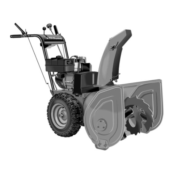
Dealer Setup
& Adjustment Instructions
Intermediate Frame Snowthrowers
Refer to the Dealer Setup & Adjustment binder Index for a
complete listing of products covered by this document.
Mfg. No. Description
7800084
I75246E, 7.5HP OHV, Snowthrower
7800085
I7524E, 7.5HP OHV, Snowthrower
7800086
EI75246E, 7.5HP OHV, Snowthrower (CE)
7800087
I7524EX, 7.5HP OHV, Snowthrower (CE)
7800138
EI75246, 7.5HP OHV Snowthrower (CE)
ATTENTION SETUP PERSONNEL:
The safety warnings provided in this guide and in
the operator's manual included with the unit contain
important information that must be obeyed when
assembling, setting-up, operating, servicing, trans-
porting, or storing the unit.
These warnings are highlighted by the safety alert triangle sym-
bol shown above, which signifies that an important safety mes-
sage is being provided.
You must read, understand, and follow these warnings and
instructions, and use safe shop and work practices at all
times while working on or around this unit and all other
outdoor power equipment.
6/2006
Sections and items denoted by the Setup symbol
provide the information necessary to fully assemble,
test, and prepare the units described above for
delivery to your customers.
Additional information concerning functional tests,
general adjustment procedures, and the location of
normal lubrication points are included in these
instructions.
TABLE OF CONTENTS:
SAFETY RULES........................................................2
Quick Setup List.......................................................3
Uncrating .................................................................4
Reduce and Check Tire Pressures .........................4
Assembly ..................................................................5
Un-Folding Handles ................................................5
Install Drift Cutters ..................................................5
Spout Rotator..........................................................6
Control Levers.........................................................6
Clean-Out Tool........................................................6
Check Fluid Levels & Fill.........................................7
Lubricate the Snowthrower.....................................7
Lubricate the Auger Shaft & Assembly..................8
Perform Safety Checks............................................9
ADJUSTMENT PROCEDURES
Auger Drive Linkage Adjustments .......................10
Traction Drive Linkage Adjustment......................10
Speed Selector Adjustment ..................................11
Discharge Control Adjustment .............................11
Scraper Bar & Skid Shoe Adjustment ..................12
Drive Belt Replacement .........................................13
Traction Drive Belt Replacement ..........................13
Auger Belt Replacement .......................................14
1
Form No. 7100731
Revision 00
TP 300-5196-00-IS-SN
Advertisement
Table of Contents

Related Manuals for Simplicity I75246E


Summary of Contents for Simplicity I75246E
-
Page 1: Table Of Contents
Dealer Setup & Adjustment Instructions Intermediate Frame Snowthrowers Refer to the Dealer Setup & Adjustment binder Index for a complete listing of products covered by this document. Mfg. No. Description 7800084 I75246E, 7.5HP OHV, Snowthrower Sections and items denoted by the Setup symbol 7800085 I7524E, 7.5HP OHV, Snowthrower provide the information necessary to fully assemble,... -
Page 2: Safety Rules
Intermediate Frame Snowthrowers SAFETY RULES Read these safety rules and follow them closely. Failure to obey these rules could result in loss of control of unit, severe personal injury or death to you, or bystanders, or damage to property or equipment. The triangle in text signifies important cautions or warnings which must be followed. -
Page 3: Setup Procedures
Intermediate Frame Snowthrowers Quick Setup List - Page Setup Procedure Steps to Perform Uncrating ❏ Reduce Tire Pressure to 20 psi (137 kPa) & Check Reduce Tire Pressures ❏ Install Drift Cutters Assembly ❏ Un-Folding Handles Assembly ❏ Connecting Shift Rods ❏... -
Page 4: Uncrating
Intermediate Frame Snowthrowers Uncrating 1. Using a reciprocating saw, cut crate sides from bot- tom skid. Lift crate from bottom skid. 2. Remove screws securing skid shoes to bottom skid. Roll snowthrower from bottom skid backwards. 3. Make sure klik-pin is inserted through hole in wheel and axle shaft and secured. -
Page 5: Assembly
Intermediate Frame Snowthrowers Assembly Un-Folding Handles Folding handles (if equipped) are shipped in the down position and need to be rotated up and secured. Cut cable ties (F, Figure 4) that secure control cables to lower handle assembly (C). Be careful not to cut or damage the control cables. -
Page 6: Spout Rotator
Intermediate Frame Snowthrowers Assembly Spout Rotator On models with folding handles the spout rotator is two pieces and needs to be connected. Remove crank han- dle (A, Figure 7) from its packaging. Slide crank handle (A) through dash (B) and slide into crank tube (C) line up holes and secure with hair pin (D). -
Page 7: Check Fluid Levels & Fill
Remove the pipe plug (A, Figure 9). The lubricant should be level with the hole. If not, add Simplicity Winter Weight Worm Gear Oil 2. Fill the engine crankcase with oil as described in the engine Owner's Manual. -
Page 8: Lubricate The Auger Shaft & Assembly
Intermediate Frame Snowthrowers Figure 15. Drive Lubrication Figure 12. Lubricate Points Where chute Contacts A. Hex Shaft Flange (Oil); Lubricate Ring Gear and Pinion Gear While Rotating Spout (Grease) Figure 13. Lubricate Points Where Control Rods Pass Thru Bracket Figure 16. Lubricating the Auger Shaft Assembly A. -
Page 9: Perform Safety Checks
Intermediate Frame Snowthrowers Perform Safety Checks Check Engine Controls 1. Make sure all safety guards are in place and all nuts, bolts, clips, cotter pins and wires are secure. 2. Check to make sure spark plug wire is attached. 3. Check all controls for proper operation: a. -
Page 10: Auger Drive Linkage Adjustments
Intermediate Frame Snowthrowers Adjustments Auger Drive Linkage Adjustment 1. With the drive lever released, the hook (B, Figure 19) should barely touch the lever (C) without raising it. There can be a maximum 1/32” clearance as shown. 2. To adjust, loosen nut (D, Figure 19) by holding the adjusting flats (A)and turning nut (D). -
Page 11: Speed Selector Adjustment
Intermediate Frame Snowthrowers Speed Selector Adjustment 1. Loosen the two nuts (A, Figure 21). 2. Place the shift lever (B, Figure 18) in 5th gear. The lower speed selector rod (B, Figure 21) will properly locate itself due to an integral spring. 3. -
Page 12: Chute Direction Control Rod Gear Adjustment
Intermediate Frame Snowthrowers Chute Direction Control Rod Gear Adjustment If the discharge chute becomes difficult to rotate or begins to operate erratically, the chute direction control rod gears may require adjustment: 1. Loosen the gear bracket mounting nuts (Figure 23). 2. -
Page 13: Drive Belt Replacement
Intermediate Frame Snowthrowers Drive Belt Traction Drive Belt & Pulley Replacement Traction Drive Belt Replacement WARNING Snowthrower must move only when the traction drive control is depressed, and must stop when the lever is released (disengaged). 1. Disconnect the spark plug wire and fasten it away from the spark plug. -
Page 14: Auger Belt Replacement
Intermediate Frame Snowthrowers Auger Drive Belt Replacement Belt Guide Screws WARNING Auger must NOT rotate unless the Auger Control Belt Guide lever has been depressed. Proper Auger Drive & Gap Belt adjustments stop the auger within 5 seconds after the Auger Control is disengaged. 1. - Page 15 Intermediate Frame Snowthrowers NOTES 6/2006 TP 300-5196-00-IS-SN...
- Page 16 NOTES M A N U F A C T U R I N G , I N C . 500 N Spring Street / PO Box 997 Port Washington, WI 53074-0997 USA © 2006 Simplicity Manufacturing, Inc. All Rights Reserved...
Need help?
Do you have a question about the I75246E and is the answer not in the manual?
Questions and answers