Advertisement
Table of Contents
Advertisement
Table of Contents

Related Manuals for Craftsman 351.215680


Summary of Contents for Craftsman 351.215680
- Page 1 8 x 36" DRUM SANDER WITH DUST COLLECTION Model No. 351.21 5680 CAUTION: Read and follow all Safety Rules and Operating Instructions before First Use of this Product. Sears, Roebuck and Co., Hoffman Estates, IL 60179 U.S.A. www.seam.com/craftsman 22118.02 Draft (05/17/04)
- Page 2 • Keep children out of workplace. Make workshop childproof. Use padlocks, master switches or remove switch keys to prevent any unintentionaluse of power tools. FULL ONE YEAR WARRANTY ON CRAFTSMAN TOOL SHOULD BE MAINTAINED DRUM SANDER • Always unplug tool prior to inspection.
- Page 3 MOUNT DRUM SANDERTO STAND Refer to Figure 2. CAUTION: The drum sander is heavy.Two people will be Refer to Figure 1. required to perform this operation. CAUTION: Do not attempt assembly if parts are missing. • Place drum sander onto stand. Make sure that holes on top Use this manual to order replacement parts.
- Page 4 Refer to Figure 5. POWER SOURCE The Craftsman Half Bag Dust Collection Set is designed to The motor is designed for operation on the voltage and fre- provide dust collectionfor woodworkingtools with a 2'/="diam- quency specified.
-
Page 5: Electrical Connections
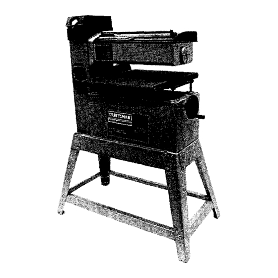
DESCRIPTION the side of the adapter must be securely connected to a The Craftsman 18 x 36" Drum Sander with leg stand is con- permanent electrical ground such as a properly grounded strocted of rugged cast iron and heavy gauge steel providing water pipe, a properly grounded outlet box or a properly stability and vibration-free operation. -
Page 6: Safety Precautions
Switch ....120 Volts, SP, Locking rocker WARNING: Some dust created by power sanding, sawing, grinding,drilling and other constructionactivitiescontains Motor ....3HP (max, developed) 3450 RPM, chemicals known to cause cancer, birth defects or other ........115V, 17 AMPS reproductiveharm. -
Page 7: Raising And Lowering
Feed Belt Speed Control Knob CAUTION: Change speeds only while machine is running, The feed belt speed control knob is located in the center of the front panel of the sander. To increase belt speed, rotate the knob counterclockwise.To decrease belt speed, rotate the knob clockwise. -
Page 8: Drum Sanding
DRUM SANDING BELT REPLACEMENT Tracking • Connect tool to power source. WARNING: Disconnect tool from power source. • Turn belt feed speed control knob to the maximum speed, The drum sanding belt is held on the drum with a spring and run the feed table several minutes to check for proper loaded clamp located on each side of the drum. -
Page 9: Feed Belt Replacement
RETURN ROLLER • Tightly wrap sanding belt around the drum keeping each wrap close to the previous edge (See Figure 17). Refer to Figure 19. iMPORTANT: Do not overlap the edges of the sanding belt. The drum sander has a return roller on the drum cover so that the workplace can be easily moved to the frontof the sander for another pass. -
Page 10: Keep Tool In Repair
• Loosen and remove four socket head bolts and the bearing bracket (See Figure 22). WARNING: Make certain that the unit is disconnectedfrom power soume before attempting to service or remove any component. CLEANING Keep machine and workshop clean. Do not allow sawdust to accumulate on the tool. - Page 11 • Use a pry bar to lift motor bracket to remove and replace • To remove and replace the variable speed belt, the outer the feed ddve belt (See Figure 24). variable speed drive pulley must be removed. Loosen and remove the socket head bolt washer and pulley (See Figure 25).
- Page 12 SYMPTOM POSSIBLE CAUSE(S) CORRECTIVE ACTION Motor will not start 1. Low voltage 1. Check power line for proper voltage 2. Open circuit inmotor or loose 2. Inspect all lead connections on motor for loose or connections open connection 3. Thermal overload protector activated 3.
- Page 13 Service Record Craftsman 18 x 36" Drum Sander with Dust Collection DATE MAINTENANCE PERFORMED REPLACEMENT PARTS REQUIRED...
- Page 14 Model 351.215680 Figure 26 - Replacement Parts Illustration for Drive...
- Page 15 PART NO. DESCRIPTION QTY. PART NO. DESCRIPTION QTY. 18151.00 Knob 22123.00 Side Cover STD863508 5-0.8 x 8mm Pan Head Screw* STD863512 5-0.8 x 12mm Pan Head Screw* STD851005 5ram FlatWasher* STD870620 6-1.0 x 20mm Socket Head Bolt* 22142.00 Cover STD870506 5-0.8 x 6mm Socket Head Bolt* 22143.00 Gear...
- Page 16 Model 351.215680 Figure 27 - Replacement Parts Illustration for Table...
- Page 17 PART NO. DESCRIPTION QTY. PART NO. DESCRIPTION QTY. 22195.00 Screw Guide 22178.00 Chain STD870620 6-1,0 x 20ram Socket Head Bolt* Dust Cover 08541,00 5-0.8 x 60mm Socket Head Bolt STD851006 6ram Flat Washer* 22306.00 Feed Belt 22180,00 idler Sprocket 22181.00 Bushing 22198.00 Spacer...
- Page 18 Model 351.215680 Figure 28 - Replacement Parts Illustration for Drum Assembly and Stand \"...
- Page 19 PART NO. DESCRIPTION QTY. 22159.00 Hood (incl Key Nos. 2-6) STD863516 6-0.8 x 16mm Pan Head Screw* 22160.00 Roller 22161.00 Hinge STD870508 5-0.8 x 8ram Socket Head Bolt" STD870616 6-1.0 x 16ram Socket Head Bolt* 22162.00 Chip Deflector 22163.00 6-1.0 x 1Omm Socket Pan Head Screw 22164.00 5-0.6 x 18ram Set Screw STD840506...
- Page 20 Your Home For repair-in your home-of all major brand appliances, lawn and garden equipment, or heating and cooling systems, no matter who made it, no matter who sold it! For the replacement parts, accessories and owner's manuals that you need to do-it-yourself. For Sears professional installation of home appliances and items like garage door openers and water heaters.
Need help?
Do you have a question about the 351.215680 and is the answer not in the manual?
Questions and answers