Table of Contents
Advertisement
MODEL NO.
917.295450
Caution:
Read and follow
all Safety Rules
and Instructions
Before Operating
This Eqmpment
MDM °
5.0 HP
26
H TiNE WIDTH
FRONTTi
E TILLER
WITH
E
=Assembly
= Operation
= Customer Responsibilities
° Service and Adjustments
° Repair Parts
i
Sears, Roebuck and Co., Hoffman Estates, IL 60179 U.S.A.
Advertisement
Table of Contents

Related Manuals for Craftsman 917.295450


Summary of Contents for Craftsman 917.295450
- Page 1 MODEL NO. 917.295450 MDM ° 5.0 HP Caution: H TiNE WIDTH Read and follow all Safety Rules FRONTTi E TILLER and Instructions WITH Before Operating This Eqmpment =Assembly = Operation = Customer Responsibilities ° Service and Adjustments ° Repair Parts Sears, Roebuck and Co., Hoffman Estates, IL 60179 U.S.A.
- Page 2 SAFETY RULES Safe Operation Practices for Walk-Behind Powered Rotary Tillers TRAINING • If the unit should start to vibrate abnormally, stop the engine (motor) and check immediately for the cause.. • Read the Owner's Manual carefully° Be thoroughly Vibration is generally a warning of trouble. familiar with the controls and the proper use of the •...
-
Page 3: Product Specifications
° if this Craftsman Tiller is used for commercial or rental purposes, this Warranty applies for only thirty (30) days from the date of purchase. WARRANTY SERVICE IS AVAILABLE BY RETURNING THE CRAFTSMAN TILLER TO THE NEAREST SEARS SERVICE CENTER/DEPARTMENT IN THE UNITED STATES. - Page 4 ..........TABLE OF CONTENTS MAINTENANCE SCHEDULE ........SAFETY RULES ............CUSTOMER RESPONSIBIUTIES ..... 3, 12-14 SERVICE & ADJUSTMENTS ........ 14-17 PRODUCT SPECIFICATIONS ........3 STORAGE ..............WARRANTY ..............TROUBLESHOOTING ..........ACCESSORIES ............. REPAIR PARTS-TILLER ........20-25 ASSEMBLY ............... REPAIR PARTS-ENGINE ........26-30 OPERATION ............
-
Page 5: Accessories
These accessories were available when the tiller was purchased. They are also available at most Sears Retail outlets, Catalog and Service Centers. Most Sears Stores can order repair parts for you when you provide the model number of your tiller. ENGINE rpLUG MUFFLER... - Page 6 MBLY Your new tiller has been assembled at the factory with exception of those parts left unassembled for' shipping purposes, To ensure safe and proper operation of your tiller' all parts and hardware you assemble must be tightened securely. Use the correct tools as necessary to insure proper tightness°...
- Page 7 UNPACK CARTON TfNE CONTROL CABLE staples when handling or disposing of CAUTION: Be careful Of exposed cartoning materia I, TfNE CONTROL HANDLE MOUNT IMPORTANT: WHEN UNPACKING AND ASSEMBLING TILLER, BE CAREFUL NOT TO STRETCH OR KiNK CABLE(S) COLUMN Cut cable ties securing handle column. Slowly lift handle column and lay it over tiller+ °...
-
Page 8: Throttle
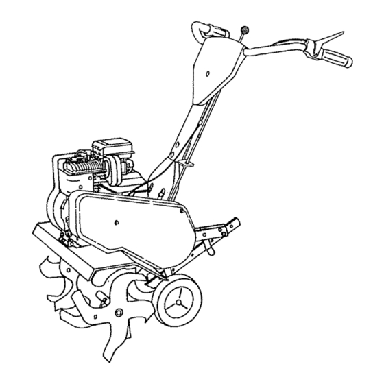
OPERATION KNOW YOUR TILLER READ THIS OWNER'S MANUAL AND SAFETY RULES BEFORE OPERATING YOUR TILLER. Compare the illustrationswith your tiller to familiarize yourself with the location of various controls and adjustments, Save this manual for' future reference. REVERSE "ftNE CONTRO!. FORWARD TINE CONTROL CHOKECONTROL THROTTLE... -
Page 9: Depth Stake
OPEBATn The operation of any tiller can result in foreign objects thrown into the eyes, which can result in severe eye damage. Always wear safety glasses or eye shields before starting your tiller and while tilling. We recommend a wide vision safety mask over the spectacles or standard safety glasses. -
Page 10: Starting
OPERATION ADD GASOLINE TRANSPORTING YOUR TILLER • Fitl fuel tank° Use fresh, c_ean, regular unleaded CAUTION: Before lifting or transport,- gasoline_ (Use of leaded gasoline will increase carbon ing, allow tiller engine and muffler to and lead oxide deposits and reduce valve life. cool. -
Page 11: Cultivating
OPEBATmON You will find tilling much easier if you leave a row untilled between passes., Then go back over the entire area at right angles (See Fig ,. 9 ),,There are two reasons for doing this_ First, wide turns are much easier to negotiate than about-faces,. -
Page 12: Maintenance Schedule
CUSTOMER RESPONSIBILITIES Jl,lll,l,lll ii II I Ill I IIIIIIHIIIIll Ill I I I I MAINTENANCE SCHEDULE FILL IN DATES AS YOU COMPLETE /Z_'-'/_/, SERVICE DATES REGU_ R SERV ICE _b"" i _"--'/ Check Engine Oil Level Change Engine Oil --'=- Oil Pivot Points inspect Spark Ar rester Muffler Inspect Air Screen... -
Page 13: Air Cleaner
CUSTOMER RESPONSIBmLUTNES Disconnect spark plug wire before performingany maintenance(except carburetor adjustment) to prevent accidental starting of engine, Preventfires! Keep the enginefree of grass, leaves,spilledoil, or fuel. Removefuel from tank beforetipping unit for maintenance. Clean mufflerarea of all grass, dirt, and debris. Do not touch hot muffler or cylinderfins as contactmay cause burns, .. -
Page 14: Finish
CUSTOMER ILITI Jill IIU Ill/,llllUJlll MU FFLER TRANSMISSION Do not operate tiller' without muffler° Do not tamper with Your transmission issealed and will only require lubrication if it is serviced. exhaust system. Damaged mufflers or spark arresters could create a fire hazard° Inspect periodically and replace CLEANING if necessary, If your engine is equipped with a spark arrester screen assembly, remove every 50 hours for... -
Page 15: Tine
FINAL CHECK "ON" POSITION MID-WIDTH TILLING - 24 INCH PATH (See Fig. 17) Assemble holes "A" in tine hubs to holes "C" in tine Withtine control"ON"(held down tohandle) push down shaft. on handte to raise tines off the ground. • Slowly pull recoil starter handle while observing tines, Tines should rotate forward, If tines do not rotate, inner wire of control cable is too... -
Page 16: V-Belt
TO REPLACE V-BELTS (See Figs. 20 and 21) FORWARDMOTION (INSIDE) V-BELT ENGINE PULLEY BELT GUIDE Replace V-belts if they have stretched considerably or if TRANSMISSION they show cracks or frayed edges° There are two (2) V- " PULLEY belts - forward (inside) and reverse (outside)° Belt guard must be removed to service belts, See "TO REMOVE BELT GUARD"... -
Page 17: Belt Guard
SERVmCE AND ADJUSTMENTS PRELIMINARY SETTING TO REMOVE BELT GUARD (See Fig. 22) Air cleaner assembly must be assembled to the carbu- • Remove two (2) cap nutsand washers from side of belt retor when making carburetor adjustments° guard_ With engine off, turn idle needle valve in (clockwise) •... -
Page 18: Storage
STORAGE ENGINE OIL Immediately prepare your tiiler for storage at the end of the season or if the unit wilt not be used for 30 days or more. Drain oil (with engine warm) and replace with clean oil, (See "ENGINE" in the Customer Responsibilities section of CAUTION: Never store the tiller with this manuaI)_... -
Page 19: Troubleshooting
TROUBLESHOOTING POINTS PROBLEM CAUSE CORRECTION Will not start Out of fuel Fi]I fuel tank Engine not"CHOKED" properly, 2., See "TO START ENGINE in the Operation section Engine flooded 3. Wait several minutes before attempting to start Dirty air cleaner, 4,, Clean or replace air clea.ner cartridge., Water in fuel, Drain fuel tank and carburetor, and refill tank with fresh gasoline... -
Page 20: Repair Parts
REPAIR PARTS TILLER - - MODEL NUMBER 917.295450 HANDLE ASSEMBLY DESCRIPTION PART PART DESCRIPTION STD533t07 STD533125 Bolt, Carriage Bolt, Carriage 5116-18 x 3/4 136998 5/16-18 UNC x 2-3/8 Grade 5 Bracket, Reverse Rod 136993 139907 Grommet Panel, Control 106932X 110512X Assembly, Handle Column Knob, Control, Reverse 110632X... -
Page 21: Type
REPAmRPARTS TILLER -- MODEL NUMBER 917.295450 BELT GUARD AND PULLEY ASSEMBLY _/;:_ PART DESCRIPTION DESCRIPTION PART 2649M Key, Square Assembly, Bracket, Belt Guard !23643X 2607J Sheave, Transmission Clip, Cable 9484R 110550X Bolt, Belt Guard Screw, Hex Washer Head, Slotted, 86777 12000036 Ring, Klip Thread Cutting #10-24 x 1/2 Type D... -
Page 22: Repair Parts
REPAIR PARTS TILLER-- MODEL NUMBER 917.295450 WHEEL AND DEPTH STAKE ASSEMBLY <, 19 20 20 19 _" PART DESCRIPTION PART DESCRIPTION 9194R Pin, Clevis 74760524 Boit, Hex 5116-18 x 1-1t2 Grade 2 74760520 Bolt, Hex Head 5!16-18 x 1-1/4 1951J500 Support, Depth Stake, L.H.. -
Page 23: Repair Parts
REPAIR PARTS TILLER -- MODEL NUMBER 917.295450 TINE ASSEMBLY DESCRIPTION PART DESCRIPTION PART 100746M Tine, Outer, R.H. 674A42 Tine, Inner, L.H. STD624008 Clip, Hairpin 100744M Tine, Outer, L.H. 674A43 Tine, Inner, R.H. 4929H Pin, Clevis... - Page 24 REPAIR PARTS TILLER - - MODEL NUMBER 917.295450 TRANSMISSION DESCRIPTION DESCRIPTION PART PAR'(' 9173R 74760524 Bolt, Hex 5/16-18 x 1-1/2 Grade 2 Spacer, Split STD541431 74780652 Bolt, Fin, Hex 3/8-16 x 3-1/4 Nut, Hex, Keps 5/16-18 UNC STD551037 Washer 13/32 x 13/16 x 11 19091412 Washer 9/32 x 7/8 x 12 Gauge 19092016...
- Page 25 REPAIR PARTS TILLER - - MODEL NUMBER 917.295450 DECALS PART DESCRIPTION 141169 Decal, Logo 133026 Decal, Logo 137737 Decal, Logo 137653 Decal, Caution, Tine Control I20431X Decal, Hand Placement 110719X Decal, Operation and Lubrication 120075X Decal, Warning, Rotating Tines 146331 Manual, Owner's(English) 146332 Manual, Owner's(Spanish)
- Page 26 REPAIR PARTS TILLER - - MODEL NUMBER 917.295450 BRIGGS & STRATTON ENGINE -- MODEL NUMBER 133202, TYPE NO. 0156-01 1019 36 35 LABEL 1058 OWNER'S llll INSTRUCTION MANUAL,...
- Page 27 RE!PARRPARTS TILLER -- MODEL NUMBER 917.295450 BRIGGS & STRATTON ENGINE - - MODEL NUMBER 133202, TYPE NO. 0156-01 _202 153 __ 202A__ ..... 190A o__19o_ ° _"...
- Page 28 REPAIR PARTS TILLER - - MODEL NUMBER 917.295450 BRIGGS & STRATTON ENGINE - - MODEL NUMBER 133202, TYPE NO. 0156-01 3°° _r REQUIRES SPECIAL TOOLS TO INSTALL SEE REPAIR INSTRUCTION MANUAL, 121 CARBURETOR OVERHAUL KIT J 3S8 Q _SKET SE'T 1016...
- Page 29 REPAIR PARTS TILLER -- MODEL NUMBER 917.295450 BRIGGS & STRATTON ENGINE - - MODEL NUMBER '133202, TYPE NO. 0156-01 KEY PART KEY PART NO. NO, DESCRIPTION NO. NO. DESCRIPTION 395990 Retainer, intake Valve and Exhaust Cylinder Assembly 93312 297565 Bushing, Cylinder Spring *Seal, Oil 260642 _...
- Page 30 REPAIR PARTS TILLER - - MODEL NUMBER 917.295450 BRIGGS & STRATTON ENGINE - - MODEL NUMBER 133202, TYPE NO. 0156-01 KEY PART KEY PART NO. NO. DESCRIPTION NO. NO. DESCRIPTION 204 222962 Bushing, Governor Lever, Flat 528 231550 Tube, Breather 205 231520 Screw, Shoulder 529 67838...
- Page 31 NOTES SERV...
-
Page 32: Replacement
1:1111 MAIl + OWNER'S 5.0 HP MANUAL 26 INCH TINE WIDTH FRONT TINE TILLER WITH REVERSE Each tiller has its own model number'+ Each engine has its own model MODEL NO. number. 917.295450 The model number for' your tiller will be found on a plate attached to the right hand engine bracket,.
Need help?
Do you have a question about the 917.295450 and is the answer not in the manual?
Questions and answers