Table of Contents
Advertisement
Advertisement
Table of Contents

Related Manuals for Craftsman 917.298350


Summary of Contents for Craftsman 917.298350
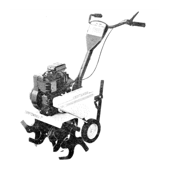
- Page 1 OWNER'S MANUAL MODEL NO. 917,298350 ® 5.0 HP Caution: TJNE WIDTH Read and follow all Safety Ru_es FRO ITT! E TILLER and instructions Before Operating This Equipment • Assembly • Operation ° Maintenance • Service and Adjustment o Repair Parts Sears, Roebuck and Co., Chicago, _L 60684 UoS°A.
-
Page 2: Accessories
SAFETY RULES Safe Operation Practices for Walk-Behind Powered Rotary Tillers • If the unit should start to vibrate abnormally, stop the TRAINING engine (motor) and check immediately for the cause. Vi- Read the operating and service instruction manual bration is generally a warning of trouble. carefully. - Page 3 Repairs necessary because of operator abuse or negligence, including bent crankshafts and the failure to maintain the equipment according to the instructionscontained in the owner's manual If this Craftsman Tiller is used for commercial or rental purposes, this Warranty applies for only 30 days from the date of purchase.
-
Page 4: Table Of Contents
TABLE OF CONTENTS MAINTENANCE ............E'T'Y RULES ............MAINTENANCE SCHEDU LE ........CUSTOMER F_ESPON S|B|LIT_ES ......... SERVICE & ADJUSTMENTS ........WARRANTY ..............STORAGE ..............PRODUCT SPECIFICATIONS ........TROU B LES HOOTIN G ..........ASSEMBLY ..............REPAIR PARTS-TILLER ........20-24 OPERATION ..............iNDEX Stopping Tines &... - Page 5 ACCESSO THESE ACCESSORIES WERE AVAILABLE WHEN THE TILLER WAS PURCHASED. THEY ARE ALSO AVAILABLE AT MOST SEARS RETAIL OUTLETS, CATALOG AND SERVICE CENTERS. MOST SEARS STORES CAN ORDER REPAIR PARTS FOR YOU WHEN YOU PROVIDE THE MODEL NUMBER OF YOUR TILLER. ENGtNE ENGKNE OIL STABMLIZER...
- Page 6 ASSE OPERATOR'S POS_TtON TO ASSEMBLE YOUR TILLER YOU WILL NEED: (1) Utility knife The right hand (R.H.) and left hand (LH.) sides of your (1) Pair of pliers tiller are determined from the operator's position while (1) Screwdriver standing behind tiller, (2) 1/2"...
- Page 7 UNPACK CARTON & INSTALL HANDLE (See iNSTALL DEPTH STAKE ASSEMBLY (See Fig. 2) Fig. 3) • insert stake support between engine bracket halves with stake spring down. WHEN HANDMNG OR DISPOSING OF NOTE: Jt may be necessary to toosen nut "A". BE CAREFUL OF EXPOSED STAPLES CARTONENG MATERIAL .
- Page 8 OP RATHON KNOW YOUR TILLER READ THIS OWNER'S MANUAL AND SAFETY RULES BEFORE OPERATING YOUR TILLER. Compare the i]Iustrationswith your tiiter to familiarize yourself with the location of various controls and adjustments. Save this manual for future reference. TINE CONTROL THROTTLE CONTROL FiG.
- Page 9 OPERATION The operation of any tiller can result Jn foreign objects thrown into the eyes, which can resutt in severe eye damage, Atways wear safety glasses or eye shiellds before startir_g your titier and while tilling. We recommend wide vision safety mask for over the spectacles or standard safety glasses, HOW TO USE YOUR TILLER...
- Page 10 OPERATION TRANSPORTING YOUR TILLER ADD GASOLINE AROUND THE YARD - •Fiil fuel tank. Use fresh, clean, regular unleaded gaso- line. (Use of leaded gasoline wil! increase carbon and o Tip depth stake forward until it is held bythe stake spring lead oxide deposits and reduce valve life.) (See Fig.
- Page 11 OPERATIC results. When tilling in the fall, remove vines and long grass to prevent them from wrapping around the tine SPARK CHOKE PLUG shaft and slowing your tilling operation. o You wilt find tilling much easier if you leave a row untilled THROTTLE between passes, Then go back over the entire area at CONTROL...
- Page 12 NTENANCE MAINTENANCE SCHEDULE FILL IN DATES AS YOU COMPLETE SERVICE DATES REGULAR SERVICE Check Engine Oil Level Change Engine Oil Oil Pivot Points _=ae==== Inspect Spark Attester Muffler Inspect Air Screen Repiace Air Cleaner Cartridge Ciean Engine Cylinder Fins Replace Spark Plug - Change more often when operating under 8 heavy toad or in h_ghambient temper_tureso 2 ..Service more often when operating in dirty or dusty conditions.
- Page 13 MAINTENANCE Disconnect spark plug wire before performing any maintenance (except carburetor adjustment) to prevent accidental starting of engine. Prevent fires! Keep the engine free of grass, leaves, spilled oil, or fuel. Remove fuel from tank before tipping unit for maintenance. Clean muffler area of all grass, dirt and debris.
- Page 14 MAINTE MUFFLER TRANSMISSION Do not operate tiller without muffler. Do not tamper with Your transmission is sealed and will not require lubrication, exhaust system. Damaged mufflers or spark arresters CLEANING could create a fire hazard. Inspect periodically and re- * Clean engine, wheels, finish, etc. of all foreign matter. place if necessary.
- Page 15 F_NAL CHECK "ON" POSiTiON - MID-WIDTH TiLLiNG _ 22 iNCH PATH (See Fig, t7) o With tine control "ON" (held down to handle) push down o AssembLe holes "A" in tine hubs to holes "C" in tine shaft. on handle to raise tines off the ground, o Slowly pull recoil starter handle whib observing tines.
-
Page 16: V-Belt
SERVICE AN ADJUSTMENTS BELT REPLACEMENT TO REPLACE V-BELT (See Fig. 20) - tnsta{i new V-belt to engine pulley first then to trans- Replace V-belt if it has stretched considerably or if it mission pulley. Be sure belt is positioned on inside shows cracks or frayed edges, groove of both pulleys, inside all belt guides and rests Belt guard must be removed to service belt. -
Page 17: Throttle
SERVICE AND ADJUSTMENTS ENGINE TO ADJUST CARBURETOR (See Fig. 22) THROTTLE LtNK,.AGE THROTTLE STOP The carburetor has been preset at the factory and ad- justment should not be necessary. However, minor ado justments may be required to compensate for differences in fuel, temperature, altitude or load. -
Page 18: Spark Plug
ENGINE immediately prepare your tiller for storage at the end of the season or if the unit wilt not be used for 30 days or Drain oil (with engine warm) and replace with clean oil more. (See "ENGINE" in the Maintenance section of this man°... -
Page 19: Type
TROUBLESHOOTI PROBLEM: Probable Cause _r. Possible Remedy WILL NOT START OR HARD TO START No gasoline in Fuel Tank Fill tank with gasoline Choke not set properly _- Place Choke Control in "CHOKE" position Throttle Control not set properly w- Place Throttle Control in "FAST"... - Page 20 REPAIR PARTS 5 HP TILLER = - MODEL NUMBER 917.298350 HANDLE ASSEMBLY PART DESCRIPTION PART DESCRIPTION STD533125 Bolt, Carriage 110512X Assembly, Handle Column 5/I6-t8 UNC x 2-3/8 Gr.5 11 98000129 Nut, Flange 127768 Panel, Control I2 STD533107 Carriage Bolt 5/16-t8 x 3/4 1t0632X Grip, Handle 13 110514X...
-
Page 21: Transmission
REPAIR PARTS 5 HP TILLER - - MODEL NUMBER 917,298350 BELT GUARD AND PULLEY ASSEMBLY PART DESCRIPTION PART DESCREPTtON 1 121313X 18 STD54!237 * Nut, Hex, Jam 3/8-16 Bracket, Belt Guard 2 9484R 19 9178R Pulley, Idler Clip 20 674A30 Idler Arm 3 86777 Screw, Hex Washer Hd. - Page 22 REPAIR PARTS 5 HP "TILLER ° ° MODEL NUMBER 917,298350 WHEEL AND DEPTH STAK5 ASSEMBLY PART DESCRIPTION PART DESCRIPTKON 74760524 Bolt, Hex 5/16q8 x 1ol/2 1 9194R Pin, Clevis 13 1951J Support, Depth Stake LH 2 7460520 Bolt, Hex 5/!6-18x lq/4 5388J Spring, Stake...
- Page 23 REPAIR PARTS 5 HP TILLER .. - MODEL NUMBER 917,298350 TINE ASSEMBLY PART DESCRIPTION PART DESCRIPTRON 674A66 Tine, Outer RH 674A63 Tine, _nner LH 3146R 674A65 Clip, Hairpin Tine, Outer LH 674A64 Tire, e , h°_nerRH 4929H Pin, Clevis...
- Page 24 REPAIR PARTS 5 HP TRLLER ° ° MODEL NUMBER 917,298350 DESCRIPTION PART 1 STD623732 * Bolt, Hex 3/8-24 x 3-!/4 Gr,5 DESCRIPTION PART * Washer '13/32 x 13/t6 x tl Ga. STD551037 STD55!137 * Washer, Lock 3/8 STD551!25 Washer, Lock t/4 * Nut 3/8-24 STD541537 74610412...
- Page 25 REPAIR PARTS 5 HP TILLE:R - - MODEL NUMBER 917.298350 ENGINE - - BRIGGS & STRATTON, MODEL NO. t 30202, "TYPE NO. 3256-01 7'41 m l_-fgl_k _PNR L_TION " t,_N'dAL Assemblies inctude aH pars shown in frames.
- Page 26 REPAIR PARTS 5 HP TMLLER - = MODEL NUMBER 917.298350 ENGINE - - BRIGGS & STRATTON, MODEL NO. 130202, TYPE NO. 3256-01 .536 Assemblies include atl parts shown in frames,...
- Page 27 REPAIR PARTS 5 HP TILLER = = MODEL NUMBER 9!7.298350 ENGINE o - BRIGGS & $TRATTON, MODEL NO. 130202, TYPE NO. 3256°,01 Assemblies include aH parts shown in frames.
- Page 28 REPAIR PARTS 5 HP TILLER o o MODEL NUMBER 9t7.298350 ENG1N5 =- 8RIGGS & STRATTON, MODEL NO. 130202, TYPE NO. 3256-01 REF. PART REF. PART REF. PART DESCRIPTION DESCRIPTION DESCRIPTION 399671 395990 Clutch Assy.-Rewin Cylinder Assembly .PISTON RING SETS: Starter 297585 Bushing-Cylinder Note:...
- Page 29 REPAIR PARTS 5 HP TILLER =- MODEL NUMBER 917.298350 ENGINE o = BRtGGS & STRATTON, MODEL NO. 130202, TYPE NO. 3256-01 REF. PART REF. PART REF. PART DESCRIPTION DESCRtPT!ON DESCRIPTION 220982 Washer 222598 Anchor Spring 262359 Link-Choke 393757 Deflector-Exhausl 391737 Gear-Governor 221377 Cap-Spring...
- Page 30 OTES SERVICE...
- Page 31 RVICE OTES...
- Page 32 ® 5.0 HP OWNER'S E WIDTH CH Tm MANUAL E TULLE FRONT T! MODEL NO. Each tiller has its own model number. Each engine has its own model 917.298350 number. The model number for your tiller will be found on a plate attached to the right hand engine bracket, The model number for your engine wil! be found on the blower housing of the engine adjacent to the spark plug,...
Need help?
Do you have a question about the 917.298350 and is the answer not in the manual?
Questions and answers