
Related Manuals for Nvidia NFORCE 780I SLI


Summary of Contents for Nvidia NFORCE 780I SLI
- Page 1 User Guide NVIDIA nForce 780i SLI Motherboard NVIDIA Corporation October, 2007 | DU-03597-001_v01...
- Page 2 780i 3-Way SLI Motherboard NVIDIA Corporation October 17, 2007 | DU-03597-001_v01...
-
Page 3: Table Of Contents
Intentions of the Kit ....................x NVIDIA nForce 780i Motherboard................1 Motherboard Specifications..................1 Unpacking and Parts Descriptions................. 3 Unpacking ......................3 Equipment......................3 NVIDIA nForce 780i SLI Motherboard ..............4 Hardware Installation....................7 Safety Instructions....................7 Preparing the Motherboard...................8 Installing the CPU .....................8 Installing the CPU Fan ..................9 Installing Memory DIMMs .................9... - Page 4 Standard CMOS Features Menu.................31 Date and Time ....................32 IDE Channel and SATA Channel ..............32 Drive A......................34 Halt On ......................34 Memory ......................35 Advanced BIOS Features ...................36 Removable Device Priority ................37 Hard Disk Boot Priority ...................37 NVIDIA Corporation October 17, 2007 | DU-03597-001_v01...
- Page 5 FSB & Memory Config ..................44 CPU Configuration..................48 System Voltages.....................50 NVMEM Memory Test..................52 Load Timing/Voltage Set.................52 Save Timing/Voltage Set.................53 System BIOS Cacheable.................53 HPET Function....................53 NVIDIA GPU Ex....................53 Integrated Peripherals Menu................54 IDE Function Setup..................55 RAID Config....................56 USB Config.....................56 NVIDIA Corporation October 17, 2007 | DU-03597-001_v01...
- Page 6 System Monitor Menu ..................64 Dynamic Fan Control ..................65 Installing Drivers and Software................67 Windows XP Drivers Install .................68 Using the NVIDIA Software................... 69 NVIDIA Performance Group of NVIDIA Control Panel..........70 Device Settings....................71 Current Hardware Settings................72 NVIDIA Corporation October 17, 2007 | DU-03597-001_v01...
- Page 7 Dynamic BIOS Access..................78 View System Information ................79 Profile Policies ....................80 Manage Your System BIOS ................81 NVIDIA System Monitor ..................82 Appendix A. POST Codes for Tritium Platform ............. 87 Appendix B. Configuring an SLI Configuration ............. 97 SLI Connector ....................97 ForceWare Driver....................98 Enabling 3-Way SLI ..................
- Page 8 Figure 31. 3-way NVIDIA SLI connector (600-10732-0000-000)......98 Figure 18. Windows Vista Device Manager............99 Figure 19. NVIDIA Control Panel, Set SLI Configuration ........100 Figure 20. SLI Visual Indicators Operating in 3DMark2006 ....... 101 NVIDIA Corporation viii October 17, 2007 | DU-03597-001_v01...
-
Page 9: Before You Begin
Parts NOT in the Kit This kit contains all the hardware necessary to install and connect your new NVIDIA® nForce® 780i SLI motherboard. However, it does not contain the following items that must be purchased separately to make the motherboard functional. -
Page 10: Intentions Of The Kit
When replacing a motherboard in a PC cabinet, you will need to reinstall an operating system even though the current drives have an operating system. NVIDIA Corporation October 17, 2007 | DU-03597-001_v01... -
Page 11: Nvidia Nforce 780I Motherboard
NVIDIA nForce 780i Motherboard Thank you for buying the NVIDIA NFORCE 780i SLI Motherboard. This motherboard offers the tools and performance PC users’ demand. When combined with two or three SLI-Ready NVIDIA GeForce graphics cards, you get innovative NVIDIA SLI Technology for enhanced system performance. - Page 12 Ø 300MBps data transfer rate Ø Six Serial ATA II connectors Ø NVIDIA MediaShield RAID with support for RAID 0, RAID 1, RAID 0+1, RAID 5, and JBOD Ø Supports hot plug and NCQ (Native Command Queuing ) Onboard LAN Ø...
-
Page 13: Unpacking And Parts Descriptions
Unpacking and Parts Descriptions Unpacking The NVIDIA nForce 780i SLI motherboard comes with all the necessary cables for adding a motherboard to a new chassis. If you are replacing a motherboard, you may not need many of these cables. Be sure to inspect each piece of equipment shipped in the packing box. If anything is missing or damaged, contact your reseller. -
Page 14: Nvidia Nforce 780I Sli Motherboard
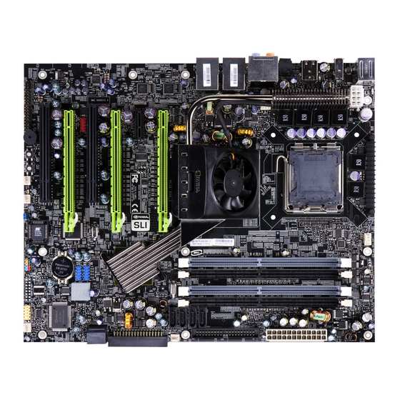
NVIDIA nForce 780i SLI Motherboard The NVIDIA nForce 780i SLI motherboard with the NVIDIA nForce 780i SLI SPP and MCP processors is a PCI Express, SLI-ready motherboard. Figure 1 shows the motherboard and Figures 2 shows the back panel connectors. -
Page 15: Figure 1. Nvidia Nforce 780I Sli Motherboard Layout
780i SLI Motherboard 1. CPU Socket 11. USB headers 21. SPDIF connector 2. NVIDIA SPP with Active fan 12. Motherboard battery 22. PCI slots 3. CPU fan connector 13. Fan connector 23. PCI Express x16 slots (SLI) 4. DDR DIMM Slots 0 - 3 14. -
Page 16: Figure 2. Chassis Backpanel Connectors
Rear Speaker Out Grey 7. Lan Port with LEDs to indicate status. Yellow/Light Up/Blink = 10 Mbps/Link/Activity Yellow and Green/Light Up/Blink = 100 Mbps/link/Activity Green/Light Up/Blink = 1000 Mbps/Link/Activity Figure 2. Chassis Backpanel Connectors NVIDIA Corporation October 17, 2007 | DU-03597-001_v01... -
Page 17: Hardware Installation
To reduce the risk of fire, electric shock, and injury, always follow basic safety precautions. Remember to remove power from your computer by disconnecting the AC main source before removing or installing any equipment from/to the computer chassis. NVIDIA Corporation October 17, 2007 | DU-03597x-001_v01... -
Page 18: Preparing The Motherboard
Lower the processor straight down into the socket Align notches with notches on the CPU with out tilting or sliding it into the socket Note: Make sure the CPU is fully seated and level in the socket. NVIDIA Corporation October 17, 2007 | DU-03597-001_v01... -
Page 19: Installing The Cpu Fan
Two DIMMs: Install into either slots 0 and 1 or 2 and 3. The idea is to not have the DIMMs in adjacent slots. Four DIMMS: Install into slots 0, 1, 2, and 3. CPU side DIMM Slot 0 DIMM Slot 2 DIMM Slot 1 DIMM Slot 3 Card-edge NVIDIA Corporation October 17, 2007 | DU-03597-001_v01... -
Page 20: Installing The Motherboard
Press the I/O shield into place and make sure it fits securely. If the I/O shield does not fit into the chassis, you would need to obtain the proper size from the chassis supplier. NVIDIA Corporation October 17, 2007 | DU-03597-001_v01... -
Page 21: Securing The Motherboard Into The Chassis
This will include: Power Connections Ø 24-pin ATX power ( PWR1 Ø 8-pin ATX 12V power ( PWR2 Internal Headers Ø Front panel Ø IEEE 1394a Ø USB Headers Ø Audio Ø Speaker Ø NVIDIA Corporation October 17, 2007 | DU-03597-001_v01... -
Page 22: Power Connections
(see Figure 3): Ø Four 6-pin (3x2) and two 8-pin (4x2) PCI-E power connectors Six 6-pin (3x2) PCI-E power connectors Ø 8-pin (4x2) PCT-E Connector 6-pin (3x2) PCI-E connector Figure 3. Power Supply Connectors NVIDIA Corporation October 17, 2007 | DU-03597-001_v01... -
Page 23: 24-Pin Atx Power (Pwr1)
Plug power cable from system power supply to PWR1 Card edge Figure 4. PWR1 Motherboard Connector Table 1. PWR1 Pin Assignments Connector Signal Signal +3.3V +3.3V +3.3V -12V PS_ON PWROK RSVD +5V_AUX +12V +12V NVIDIA Corporation October 17, 2007 | DU-03597-001_v01... -
Page 24: 8-Pin Atx 12V Power (Pwr2)
Connect the gray connector to a slave device. If you install two hard disk drives, you must configure the second drive as a slave device by setting its jumper accordingly. Refer to the hard disk documentation for the jumper settings. NVIDIA Corporation October 17, 2007 | DU-03597-001_v01... - Page 25 If an ATA-66/100 disk drive and a disk drive using any other IDE transfer protocol are attached to the same cable, the maximum transfer rate between the drives may be reduced to that of the slowest drive. NVIDIA Corporation October 17, 2007 | DU-03597-001_v01...
-
Page 26: Connecting Serial Ata Cables
RAID 1, RAID 5, RAID 0+1 and JBOD configurations. SATA 3 SATA 4 SATA 6 SATA 5 SATA 1 (bottom) Connect the locking cable end to the motherboard connector. SATA 2 (top) Connect the end without the lock to the drive. NVIDIA Corporation October 17, 2007 | DU-03597-001_v01... -
Page 27: Connecting Internal Headers
LED indicates the activity status of the hard disks. RESET Attach the Reset switch cable from the front panel of the case to these two pins. The system restarts when the switch is pressed. RESET NVIDIA Corporation October 17, 2007 | DU-03597-001_v01... -
Page 28: Ieee 1394A
Connect the two ends of the cables to the IEEE 2394 connectors on the are going to motherboard. ship with your kit. Table 3. IEEE 1394a Connector Pins Connector Signal TPA+ IEEE 1394a Connector TPA- TPB+ TPB- +12V +12V Empty NVIDIA Corporation October 17, 2007 | DU-03597-001_v01... -
Page 29: Usb Headers
Connect the two ends of the cables to the USB 2.0 headers on the motherboard. Table 4. USB 2.0 Header Pins Connector Signal USB 2.0 Header Connector 5V_DUAL Empty Signal 5V_DUAL No Connect NVIDIA Corporation October 17, 2007 | DU-03597-001_v01... -
Page 30: Audio
Front Audio, the Rear Audio. The front Audio supports re-tasking function. Table 5. Front Audio Connector Connector Signal Front Audio Connector PORT1_L AUD_GND PORT1_R PRECENCE_J PORT2_R SENSE1_RETURN SENSE_SEND Empty PORT2_L SENSE2_RETURN NVIDIA Corporation October 17, 2007 | DU-03597-001_v01... -
Page 31: Fan Connections
780i SLI SPP/MCP fan connector. Fan Connector Install the fan over the nForce 780i SLI SPP to draw heat from the MCP. The fans plug into a 3- pin connector. +12V SENSE NVIDIA Corporation October 17, 2007 | DU-03597-001_v01... -
Page 32: Com1
The motherboard kit provides an additional serial COM header for your machine. Connect one side of a switching cable to the header and then attach the serial COM device to the other side of the cable. NVIDIA Corporation October 17, 2007 | DU-03597-001_v01... -
Page 33: Fdd Connector
(FDD). Expansion Slots The NVIDIA nForce 780i SLI motherboard contains six expansion slots, four PCI Express slots and two PCI slots. For a full list of PCI Express x16 graphics card supported by this motherboard, go to www.nvidia.com/estore... -
Page 34: Pci Express X1 Slot
4GB/sec (8GB/sec concurrent). The design of this motherboard supports three PCI-Express graphics cards using NVIDIA’s SLI technology with multiple displays. When installing a PCI Express x16 card, be sure the retention clip snaps and locks the card into place. -
Page 35: Jumper Settings
Turn off the AC power supply and connect pins 1 and 2 together using the jumper cap. Return the jumper setting to normal (pins 2 and 3 together with the jumper cap). Turn the AC power supply back on. NVIDIA Corporation October 17, 2007 | DU-03597-001_v01... - Page 36 780i 3-Way SLI Motherboard This page is blank. NVIDIA Corporation October 17, 2007 | DU-03597-001_v01...
-
Page 37: Configuring The Bios
Setup menus. Detailed descriptions of the BIOS parameters are also provided. This section includes the following information: Enter BIOS Setup Main Menu Standard CMOS Features Advanced BIOS Features Advanced Chipset Features Integrated Peripherals Power Management Setup PnP/PCI Configurations System Monitor NVIDIA Corporation October 17, 2007 | DU-03597x-001_v01... -
Page 38: Enter Bios Setup
Note that on the BIOS screens all data in white is for information only, data in yellow is changeable, data in blue is non-changeable, and data in a red box is highlighted for selection. NVIDIA Corporation October 17, 2007 | DU-03597-001_v01... -
Page 39: Figure 5. Bios Cmos Setup Utility Main Menu
Use this menu to set up onboard peripherals such as IDE, RAID, USB, LAN, and MAC control. Power Management Setup Use this menu to configure power management, power on, and sleep features. PnP/PCI Configurations Use this menu to modify the system’s Plug-and-Play and PCI configurations. NVIDIA Corporation October 17, 2007 | DU-03597-001_v01... - Page 40 SLI-Ready Memory is a status indicator displayed at the bottom of the BIOS screen. The three status indicators are: Enabled: SLI-Ready memory is detected and enabled. Disabled: SLI-Ready memory is detected but disabled. Not Detected: SLI-Ready memory is not detected. NVIDIA Corporation October 17, 2007 | DU-03597-001_v01...
-
Page 41: Standard Cmos Features Menu
Standard CMOS Features Menu Note: Note that all data in white is for information only, data in yellow is changeable, data in blue is non-changeable, and data in a red box is highlighted for selection. NVIDIA Corporation October 17, 2007 | DU-03597-001_v01... -
Page 42: Date And Time
Capacity 0 MB SATA Channel sub- menu Cylinder IDE Auto-Detect [Press Enter] Head Precomp Extended IDE Drive [None} Landing Zone Access Mode Auto Sector Capacity 0 MB Cylinder Head Precomp Landing Zone Sector NVIDIA Corporation October 17, 2007 | DU-03597-001_v01... - Page 43 For HDD less than 528 MB. Ø For HDD greater than 528 MB and #$:Move ENTER:Accept ESC:Abort supporting LBA (Logical Block Addressing). Ø Large For HDD greater than 528 MB but not supporting LBA. Ø Auto Recommended mode. NVIDIA Corporation October 17, 2007 | DU-03597-001_v01...
-
Page 44: Drive A
All , But Keyboard ..[ ] ystem boot does not stop for any detected All , But Diskette ..[ ] All , But Disk/Key ..[ ] errors. NVIDIA Corporation #$:Move ENTER:Accept ESC:Abort October 17, 2007 | DU-03597-001_v01... -
Page 45: Memory
(or conventional) memory installed in the system. Extended Memory BIOS determines how much extended memory is present during the POST. Total Memory This value represents the total memory of the system. NVIDIA Corporation October 17, 2007 | DU-03597-001_v01... -
Page 46: Advanced Bios Features
Advanced BIOS Features Menu Note: Note that all data in white is for information only, data in yellow is changeable, data in blue is non-changeable, and data in a red box is highlighted for selection. NVIDIA Corporation October 17, 2007 | DU-03597-001_v01... -
Page 47: Removable Device Priority
Page Up keys to scroll through the options or press to display the Page Down Enter options in a sub-menu. Use the #$ arrow keys to position the selector in the option you choose. NVIDIA Corporation October 17, 2007 | DU-03597-001_v01... -
Page 48: Quick Power On Self Test
Boot Up NumLock Status This option allows you to select the power-on state of . Select NumLock activate the keyboard when the system is started. Select to disable NumLock key. NumLock NVIDIA Corporation October 17, 2007 | DU-03597-001_v01... -
Page 49: Security Option
Full Screen LOGO Show This option allows you to enable or disable the display of the full-screen logo when the system boots. Use the keys to toggle Page Up Page Down between Enable Disable NVIDIA Corporation October 17, 2007 | DU-03597-001_v01... -
Page 50: Advanced Chipset Features
NVMEM memory test [Disable] Voltage control Load timing/voltage set [Press Enter] Save timing/voltage set [Press Enter] System BIOS Cacheable [Disabled] HPET Function [Enable] NVIDIA GPY Ex [Enable] #$"!:Move Enter:Select +/-/PU/PD:Value F10:Save ESC:Exit F1:General Help F5: Previous Values F7:Defaults Figure 8. -
Page 51: System Clocks
System Clocks Menu Note: Note that all data in white is for information only, data in yellow is changeable, data in blue is non-changeable, and data in a red box is highlighted for selection. NVIDIA Corporation October 17, 2007 | DU-03597-001_v01... -
Page 52: Frequency Settings
PCI Express Bus, Slot 3 (the black slot farthest from the CPU). SPP< >MCP Ref Clock, MHz — Use the keys to scroll through the frequency Page Up Page Down options for the reference clock between the SPP chip and the MCP chip. NVIDIA Corporation October 17, 2007 | DU-03597-001_v01... -
Page 53: Ht Multiplier
SPP PCIe. Option values are , and [Disabled] [UP Spread] This option reverts to and cannot be changed [Center Spread]. Disabled when the value for PCIe x16_1 exceeds 100MHz. PCIe Spread Spectrum(MCP) Disabled SATA Spread Spectrum Disabled NVIDIA Corporation October 17, 2007 | DU-03597-001_v01... -
Page 54: Fsb & Memory Config
SLI-Ready Memory Use the keys to scroll through the SLI-Ready Page Up Page Down Memory options. The options are: Ø Disabled Ø CPUOC 0% Ø CPUOC 1% Ø CPUOC 2% Ø CPUOC 3% NVIDIA Corporation October 17, 2007 | DU-03597-001_v01... - Page 55 As the FSB speed is changed, changes CPU Freq, MHz proportionally. FSB – Memory Clock Mode [Linked] FSB (QDR), MHz [1067] 1066.7 Actual FSB (QDR), MHz 1066.7 MEM (DDR), MHz [1067] 800.6 Actual MEM (DDR), MHz 800.0 NVIDIA Corporation October 17, 2007 | DU-03597-001_v01...
-
Page 56: Memory Timing Setting
F1:General Help[ F5: Previous Values F7:Defaults Ø Optimal Use the Page Up Page Down keys to select Optimal Optimal. prohibits you from manually setting any timing. All timing is set for optimal performance. NVIDIA Corporation October 17, 2007 | DU-03597-001_v01... - Page 57 : This is the minimum write-to-read delay with the same chip tWTR selected (options are 1 through 10). : This is the DRAM refresh rate (options are , and tREF Auto 7.8uS 3.9uS NVIDIA Corporation October 17, 2007 | DU-03597-001_v01...
-
Page 58: Cpu Configuration
Use this function to enable or disable TM1 and TM2 support. Options are: Ø Disable Disable support for TM1 and TM2. Ø TM1 Only The CPU is thermally throttled by cutting active processor clock cycles. NVIDIA Corporation October 17, 2007 | DU-03597-001_v01... - Page 59 When this function is enabled, it allows a VMM to utilize the additional hardware capabilities provided by Intel Virtualization Technology. CPU Core 1 This function allows you to enable or disable CPU Core. NVIDIA Corporation October 17, 2007 | DU-03597-001_v01...
-
Page 60: System Voltages
CPU FSB. [Auto] Memory This function defines the voltage level for the DRAM. Use the Page Up keys to select a voltage or select to automatically set the Page Down [Auto] voltage. NVIDIA Corporation October 17, 2007 | DU-03597-001_v01... - Page 61 Page Down to automatically set the voltage. [Auto] HT nForce SPP <-> MCP This function defines the voltage level for the NVIDIA HT nForce SPP <-> MCP Link. Use the keys to select a voltage or select Page Up Page Down to automatically set the voltage.
-
Page 62: Nvmem Memory Test
780i 3-Way SLI Motherboard NVMEM Memory Test This function defines whether you run the NVIDIA memory testing module during POST. The options are Fast, Medium, Slow, and Disable. Load Timing/Voltage Set This function loads the system voltages and timing settings that were defined in the System Voltages menu. -
Page 63: Save Timing/Voltage Set
, the APIC Disabled timer is used. NVIDIA GPU Ex To enable or disable this function you need to have the NVIDIA® ForceWare® graphics driver with NVIDIA EX support. When enabled, the system uses the optimized NVIDIA EX graphics driver. NVIDIA Corporation... -
Page 64: Integrated Peripherals Menu
HD Audio [Auto] IDE HDD Block Mode [Enabled] Onboard FDC Controller [Enabled] Onboard Serial Port 1 [3FB/IRQ4] #$"!:Move Enter:Select +/-/PU/PD:Value F10:Save ESC:Exit F1:General Help F5: Previous Values F7:Defaults Figure 13. Integrated Peripherals Menu NVIDIA Corporation October 17, 2007 | DU-03597-001_v01... -
Page 65: Ide Function Setup
This function allows you to enable specific SATA controllers, enable all controllers, or disable all controllers. The options available are [SATA-0] , and [SATA-0+1] [Enable All] [Disabled] IDE Prefetch Mode Use this function to enable or disable the IDE Prefetch mode NVIDIA Corporation October 17, 2007 | DU-03597-001_v01... -
Page 66: Raid Config
OnChip USB [Disabled] [V1.1+V2.0] [V1.1] USB Keyboard Support Enabled USB Keyboard/Mouse USB Mouse Support Enabled Support Use these function to enable or disable the onchip WSB support of the keyboard and/or mouse. NVIDIA Corporation October 17, 2007 | DU-03597-001_v01... -
Page 67: Nvidia Corporation October 17, 2007 | Du-03597-001_V01
Select if your drive does not support block mode. [Disabled] Onboard FDC Controller This function on the Integrated Peripherals menu allows you to enable or disable the onboard FDC controller function. NVIDIA Corporation October 17, 2007 | DU-03597-001_v01... -
Page 68: Onboard Serial Port 1
0 : 0 : 0 POWER ON Function [BUTTON ONLY] KB Power ON Password Enter Hot Key Power On Ctrl-F1 #$"!:Move Enter:Select +/-/PU/PD:Value F10:Save ESC:Exit F1:General Help F5: Previous Values F7:Defaults Figure 14. Power Management Setup Menu NVIDIA Corporation October 17, 2007 | DU-03597-001_v01... -
Page 69: Acpi Function
[0 : 0 : 0] To enter a day or time, use the keys to scroll through Page Up Page Down numbers or enter the number using the keyboard number or the keys. – NVIDIA Corporation October 17, 2007 | DU-03597-001_v01... -
Page 70: Power On Function
To select a hot key use though Ctrl+F1 Ctrl+F12 POWER ON Function [Hot key] KB Power ON Password Enter Hot Key Power On [Ctrl-F1] Mouse Left Mouse Right Any Key NVIDIA Corporation October 17, 2007 | DU-03597-001_v01... -
Page 71: Pnp/Pci Configuration Menu
Resources Controlled By [Auto(ESCD)] IRQ Resources Press Enter ** PCI Express relative items ** Maximum Payload Size [4096] #$"!:Move Enter:Select +/-/PU/PD:Value F10:Save ESC:Exit F1:General Help F5: Previous Values F7:Defaults Figure 15. PnP/PCI Configuration Menu NVIDIA Corporation October 17, 2007 | DU-03597-001_v01... -
Page 72: Init Display First
If you select so you can assign the resources, [Manual] is enabled for input. Resources Resources Controlled By [Auto(ESCD)] x IRQ Resources Press Enter Resources Controlled By [Manual)] IRQ Resources [Press Enter] NVIDIA Corporation October 17, 2007 | DU-03597-001_v01... -
Page 73: Irq Resources
TLP payload size (in bytes) for the PCI Express devices. Use the keys to scroll through sizes or enter the number using Page Up Page Down the keyboard numbers or use the keys to go up and down the list of – sizes. NVIDIA Corporation October 17, 2007 | DU-03597-001_v01... -
Page 74: System Monitor Menu
F5: Previous Values F7:Defaults Figure 16. System Monitor Menu All of the values shown in are dynamic and change as the speed and Blue voltages of the various components change with system usage. NVIDIA Corporation October 17, 2007 | DU-03597-001_v01... -
Page 75: Dynamic Fan Control
0% to 100%. [Manual] Set the desired speed for the Aux, nForce, and Chassis fans from 0% to 100%. The system defaults to 100%. NVIDIA Corporation October 17, 2007 | DU-03597-001_v01... - Page 76 780i 3-Way SLI Motherboard This page is blank. NVIDIA Corporation October 17, 2007 | DU-03597-001_v01...
-
Page 77: Installing Drivers And Software
The motherboard supports Windows XP 32bit and 64bit and is Vista-capable. The kit comes with a CD that contains utility drivers and additional NVIDIA software. The CD that has been shipped with your NVIDIA motherboard contains the... -
Page 78: Windows Xp Drivers Install
When installing the graphics drivers, the resolution defaults to the lowest setting (typically 800 x 600), making your display very large. Adjust accordingly. Insert the NVIDIA nForce 780i SLI installation CD for the graphics drivers included in the kit. Note: If you have multiple graphics cards installed, you will be asked multiple times for all events once the drivers are installed. -
Page 79: Using The Nvidia Software
Using the NVIDIA Software Built upon the foundation of NVIDIA’s core motherboard and GPU technologies, NVIDIA System Monitor and Performance Server software utilities bring consolidated reporting and control to the desktop in seamless fashion. Traditionally, users have been forced to endure a sequence of trial and error attempts within the BIOS in order to customize the operation and performance of the system to their needs. -
Page 80: Nvidia Performance Group Of Nvidia Control Panel
Historically, NVIDIA’s Control Panel has contained a wealth of settings and adjustments for NVIDIA GPU’s. In similar fashion, the new NVIDIA Performance Group applies the same depth of control to the rest of the components within a system. -
Page 81: Device Settings
Using NVIDIA Software Device Settings Device Settings has two tabs, Current Hardware Settings Hardware . Under the tab there are settings for the Profiles Current Hardware Settings CPU, Motherboard, Memory, and GPU. NVIDIA Corporation October 17, 2007 | DU-03597-001_v01... -
Page 82: Current Hardware Settings
CAUTION: Increasing the voltage or the clock speed of a component may void its warranty due to exceeding recommended specifications. NVIDIA and the board manufacturer are not responsible for damage that may occur when component tolerances are exceeded. - Page 83 Using NVIDIA Software Motherboard Motherboard option showcases a wide variety of motherboard and system-wide options and settings. The controls located in the Adjust Motherboard Timings screen allow the bus speeds to be adjusted manually to increase performance for gaming, or lower performance to conserve power and create a quieter user environment.
- Page 84 The lower this value, the faster the performance. However, if it is set too low it can cause data corruption by deactivating the row to soon. Adjustable from 1 to 63. NVIDIA Corporation October 17, 2007 | DU-03597-001_v01...
- Page 85 Using NVIDIA Software Write Recovery Time Memory timing that determines the delay between a write command and a Precharge command is set to the same bank of memory. Adjustable from 1 to W to R Termination Turnaround The Write-to-Read time is the number of clock cycles between the last write data pair and the subsequent READ command to the same physical block.
- Page 86 The Command Per Clock (tCPC) sets the Command Rate for the memory controller. The value shown cannot be changed Async Latency This value is filled in by the system and can not be changed by the user. NVIDIA Corporation October 17, 2007 | DU-03597-001_v01...
- Page 87 Using NVIDIA Software The graphics processing unit (GPU) located on your video card(s) can be adjusted using interface. You can override the shipped clock Device Setting frequencies of your GPU and GPU memory, and you can set the GPU fan speed.
-
Page 88: Dynamic Bios Access
When finished making your changes, click the Note This feature is available only with BIOS support from the motherboard manufacturer. Available screen and features will vary between different makes and models of motherboards. NVIDIA Corporation October 17, 2007 | DU-03597-001_v01... -
Page 89: View System Information
Using NVIDIA Software View System Information View System Information menu is a high-level view where all the critical values of the system are consolidated and presented within a single view. At a glance, the user can clearly see the current status of their components and receives a clear depiction of overall system performance. -
Page 90: Profile Policies
780i 3-Way SLI Motherboard Profile Policies Easily one of the most powerful aspects of NVIDIA Performance Server is the ability to create custom profiles and rules. Essentially, NVIDIA Performance Server allows the user to offer a custom set of settings and alerts which can be tailored from a global setting all the way to something as granular as a particular game. -
Page 91: Manage Your System Bios
Using NVIDIA Software Manage Your System BIOS Thanks to the power and flexibility of NVIDIA’s Performance Server software, users can even backup or update their system BIOS from within Windows. In addition to displaying a complete collection of information regarding the current BIOS version being used, the user also has the option of saving a backup version of the BIOS being used. -
Page 92: Nvidia System Monitor
All ProgramsÚNVIDIA CorporationÚNVIDIA System Monitor The NVIDIA System Monitor is a unique 3D presentation of core component values. For every supported device, a wide range of information ranging from temperature, frequency, and voltage are reported. Given the fact that the NVIDIA System Monitor is based around an OpenGL foundation, there is nearly zero performance overhead associated with running the utility. - Page 93 Using NVIDIA Software In this example, we can see that the motherboard is selected. As a result, a wide array of related settings and status information is displayed in real-time. In addition to fan speeds and temperatures, we also find critical voltage values for core components.
- Page 94 The user can control everything from temperature units to overall translucency of the application, and can manipulate a number of other settings to tailor the program to one’s liking. NVIDIA Corporation October 17, 2007 | DU-03597-001_v01...
- Page 95 Using NVIDIA Software The second series of options the user can alter deals with Event Logging. Here, one can easily select which system components to track and can specify the name of the resulting output file. All fields within the application will be logged and written to this file to aid in troubleshooting issues and tracking overall system behavior.
- Page 96 In this screen, the user simply enters their desired hotkey configuration and they are able to control every aspect of functionality for Monitor according to their own personal preferences. NVIDIA Corporation October 17, 2007 | DU-03597-001_v01...
-
Page 97: Appendix A. Post Codes For Tritium Platform
Test the Keyboard Reserved Mouse Init Initialized the mouse Reserved Reserved Reserved CheckSum Check Check the integrity of the ROM,BIOS and message Reserved Autodetect Check Flash type and copy flash write/erase routines EEPROM NVIDIA Corporation October 17, 2007 | DU-03597x-001_v01... - Page 98 Init PNP Shadow VBIOS Shadow system/video BIOS Clock Gen Init onboard clock generator and sensor Setup BDA Setup BIOS DATA AREA (BDA) Reserved CPU Speed detect Chipset programming and CPU Speed detect Reserved NVIDIA Corporation October 17, 2007 | DU-03597-001_v01...
- Page 99 Verify 8259 Channel 1 masked interrupts by alternately turning off and on the interrupt lines. Reserved Test 8259-2 Mask Verify 8259 Channel 2 masked interrupts by alternately turning off and on the interrupt lines. Reserved NVIDIA Corporation October 17, 2007 | DU-03597-001_v01...
- Page 100 8086 mode, page mode and clear the memory Reserved Reserved CPU display Detect CPU speed and display CPU vendor specific version string and turn on all necessary CPU features Reserved PnP Init Display PnP logo and PnP early init Reserved NVIDIA Corporation October 17, 2007 | DU-03597-001_v01...
- Page 101 Enter setup check and autoconfiguration check up Reserved Initialize Floppy Initialize floppy disk drive Reserved FDD install Install FDD and setup BIOS data area parameters Reserved Reserved Reserved Initialize Hard Initialize hard drive controller Drive NVIDIA Corporation October 17, 2007 | DU-03597-001_v01...
- Page 102 Display PNP Display PNP devices USB Final Init Final USB initialization Reserved Reserved Reserved Setup ACPI tables Setup ACPI tables Reserved Option ROM Scan for Option ROMs Detect Reserved Enable Parity Enable Parity Check NVIDIA Corporation October 17, 2007 | DU-03597-001_v01...
- Page 103 Unclaimed NMI If unmasked NMI occurs, display Press F1 to disable NMI, F2 reboot. Program MCP To program chipset from defaults values Setup Pages E1- Page 1, E2 - Page 2, etc. Boot NVIDIA Corporation October 17, 2007 | DU-03597-001_v01...
- Page 104 PROD_E: PROD w/ Expandable criteria 01Bh Send MRS/EMRS configuration cycles 01Ch Overvoltage handling 01Dh PROD_F: PROD Final - after MRS/EMRS 020h PCI Express Initialization 030h Load Spread Spectrum tables 040h Set Top-Of-Memory registers NVIDIA Corporation October 17, 2007 | DU-03597-001_v01...
- Page 105 0FBh No DIMMs present 0FAh Invalid DIMM types, SDR/DDR 0F9h Different voltage levels 0F8h Invalid REFRESH Rate 0F7h Invalide memory geometry 0F6h Slam Engine error 0F5h Memory Test Error 0F4h Link Training timeout NVIDIA Corporation October 17, 2007 | DU-03597-001_v01...
- Page 106 780i 3-Way SLI Motherboard NVIDIA Corporation October 17, 2007 | DU-03597-001_v01...
-
Page 107: Appendix B. Configuring An Sli Configuration
Configuring an SLI Configuration NVIDIA SLI (Scalable Link Interface) is a revolutionary technology that allows two NVIDIA SLI graphics cards to work together to deliver incredible 3D graphics performance. Your new motherboard can support up to three PCI Express graphics cards linked using SLI. -
Page 108: Forceware Driver
Figure 17. 3-way NVIDIA SLI connector (600-10732-0000-000) ForceWare Driver The 3-way SLI platform uses the NVIDIA ForceWare Windows Vista driver. To install the driver, run the setup.exe file to launch thee . The InstallShield runs three installs, one for each GPU. Reboot your PC when the InstallShield install is complete. -
Page 109: Figure 18. Windows Vista Device Manager
Configuring 3-Way SLI Three GPUs are represented under Display adapters Figure 18. Windows Vista Device Manager NVIDIA Corporation October 17, 2007 | DU-03597-001_v01... -
Page 110: Enabling 3-Way Sli
780i 3-Way SLI Motherboard Enabling 3-Way SLI 3-way NVIDIA SLI is enabled from the . Right mouse NVIDIA Control Panel click on the Windows desktop and select NVIDIA Control Panel. Go to Ú (Figure 19) and select Settings Set SLI configuration Enable SLI technology . -
Page 111: Figure 20. Sli Visual Indicators Operating In 3Dmark2006
Configuring 3-Way SLI Before closing the NVIDIA Control Panel, go to the top menu option labeled and select 3D Settings Show SLI Visual Indicators This option overlays a text label of SLI x3 and green SLI scaling bars in fullscreen 3D applications, as seen in Figure 20. -
Page 112: Verifying 3-Way Sli Is Active
SLI Visual indicators. If these visual indicators are visible and there is no flickering or flashing, 3-way NVIDIA SLI is operational on your platform. If these visual indicators are not visible, please check previous steps to ensure you have enable the indictors, your connector is firmly in place, and that you have enable SLI technology. -
Page 113: Index
BIOS CMOS Setup Utility Main Menu, Chassis Backpanel Connectors, 6 CHS, 33 BIOS menus Clock Drive Strength, 76 Advanced BIOS Features menu, 36 CMOS RAM jumper, 25 Advanced Chipset Features, 40 Comm2 Bracket Cable, 4 NVIDIA Corporation October 17, 2007 | DU-03597x-001_v01... - Page 114 FSB & Memory Config menu, 44 CPU Spread Spectrum, 43 FSB (QDR), 46 CPU Thermal Control, 48 FSB and Memory Clock Mode, 45 CPU, installing, 8 FSB Reference Clock, 42 CPU, setting parameters, 72 full-screen logo, 39 NVIDIA Corporation October 17, 2007 | DU-03597-001_v01...
- Page 115 IEEE 1934a Connector Pins, 18 set CPU parameters, 72 installing set date and time, 32 CPU, 8 set disk priority, 37 I/O shield, 10 set fan speeds in BIOS, 64 memory DIMMs, 9 NVIDIA Corporation October 17, 2007 | DU-03597-001_v01...
- Page 116 Network Boot Priority, 37 Intel microprocessor, ix NumLock status, 38 internal headers, 17 NVIDIA EX support, 53 PWRHD_LED, 17 NVIDIA memory testing module, 52 PWRLED, 17 NVIDIA nForce 780i SE Motherboard, PWRSW, 17 NVIDIA nForce 780i SE Motherboard IRQ Resources, 63...
- Page 117 Ref Clock, SPP1 MCP, 42 tRAS, 47, 74 Refresh Rate, 75 tRC, 47 removable device startup priority, 37 tRDC, 47 RESET, 17 tRDRD, 75 Reset switch cable, 17 tREF, 47 Row Address Strobe, 74 NVIDIA Corporation October 17, 2007 | DU-03597-001_v01...
- Page 118 Virtualization Technology, 49 tWRWR, 76 W to R Termination Turnaround, 75 tWTR, 47 Write Recovery Time, 75 unpacking the kit, 3 Write-to-Write timing, 76 USB 2.0 4-Port Cable, 4 USB 2.0 ports, 19 NVIDIA Corporation October 17, 2007 | DU-03597-001_v01...
- Page 119 No license is granted by implication or otherwise under any patent or patent rights of NVIDIA Corporation. Specifications mentioned in this publication are subject to change without notice. This publication supersedes and replaces all information previously supplied.
- Page 120 NVIDIA Corporation October 17, 2007 | DU-03597-001_v01...
Need help?
Do you have a question about the NFORCE 780I SLI and is the answer not in the manual?
Questions and answers