
Related Manuals for Craftsman 917.256922


Summary of Contents for Craftsman 917.256922
- Page 1 (RI:IFTXMI:1 N MODEL NUMBER 917.256922 OWNER'S MANUAL oAssembly oOperation oCustomer Responsibilities oService oAdjustments oRepair Parts Caution: Read and Follow all Safety Rules and Instructions Before Operating This Equipment...
- Page 2 SAFETY RULES Safe Operation Practices for Ride-On Mowers IMPORI"ANT: THIS CUTTING MACHINE IS CAPABLE OFAMPUTAT1NG HANDS AND FEET AND TH ROWING OBJECTS, FAILURE TOOBSERVETHE FOLLOWING SAFETY INSTRUCTIONS COULD RESULT IN SERIOUS INJURY OR DEATH. GENERAL OPERATION CHILDREN • Read, understand, and follow alt instructions in the manual Tragic accidents can occur if the operator is not alert to the and on the machine before stagging.
-
Page 3: Maintenance
PRODUCT SPECIFICATIONS CONGRATULATIONS on your purchase of a Sears trac- tor,. It has been designed, engineered and manufactured HORSEPOWER: to give you the best possible dependability and perfor- mance. GASOLINE CAPACITY: 14 GALLONS Should you experience any problem you cannot easily UNLEADED REGULAR remedy, please... - Page 4 TABLE OF CONTENTS ..i..i,,i,, ........... ,Ull OPERATION ............10-'13 SAFETY RULES ............MAINTENANCE SCHEDULE ........PRODUCT SPECIFICATIONS ........SERVICE AND ADJUSTMENTS ......18-22 CUSTOMER RESPONSIBILITIES ..... 3, 14-'17 STORAGE ..............WARRANTY ..............TROUBLESHOOTING ........... 24,-25 TABLE OF CONTENTS ..........
-
Page 5: Accessories
, H=I , , =I,"H'H ......II I I=INH,H= ACCESSORIES AND ATTACHMENTS ......i IIIIIIH= N,=,II= ii 1,1111111,11 These accessories and attachments were available when the unit was purchased. They are also available at most Sears retail outlets, catalog and service centers. Most Sears stores can order these items for you when you providethe model number of your tractor. MAINTENANCE ENGINE SPARK PLUG... - Page 6 ,,,= ,,,i,=,,i ......i ,=,,=, IHH'H HARDWARE PACK CONTENTS ,1== ..,,u= ,,u,,,,H ,ul,,= Parts packed separately in carton Parts Bag contents shown full size ,1 ....==,,, (1) Large Flat Washer Seat © Battery acid Steering (1) Locknut 3/8-24 Wheel Battery Steering...
-
Page 7: Tools Required
ASSEMBLY ,=,,,,, ..=1 ,, Your new tractor has been assembled at the factory with the exception of those parts left unassembled for shipping purposes. To ensure safe and proper operation of your tractor, all parts and hardware you assemble must be tightened securely. Use the correct tools as necessary to insure proper tightnes&... - Page 8 lU ..i,U,UlUll,,nll,,,,n ..ii,l,,ll,ii I " I,'1 ASSEMBLY ..i ....,M,, HOW TO SET UP YOUR TRACTOR INSTALL SEAT (See Fig. 4) Adjust seat before tightening adjustment bolt. PREPARE BATTERY (See Fig, 3) Remove cardboard packing on seat pan_ Place seat on pan and assemble shoulder bolt.
-
Page 9: Install Battery
..,,,-, , ....-,,,,,,,i, ii iiiii1,,,11 ASSEMBLY INSTALL BATTERY (See Figs. 5 & 6) ..i,iiiiiiii CAUTION: Do not short battery termi- nals+ Before installing battery, remove rings, etc. metal bracelets, wristwatch bands, Positive terminal must be connected first to prevent sparking from acciden- tal grounding. -
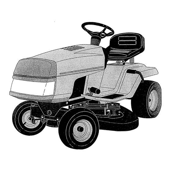
Page 10: Operation
OPERATION KNOW YOUR TRACTOR READ THIS OWNER'S MANUAL & SAFETY RULES BEFORE OPERATING YOUR TRACTOR. Compare the illustrations with your tractor to familiarize yourself with the Iocation of various controls and adjustments. Save this manual for future reference_ THROTTL_ CHOKE _TROL FUEL CAP CLUTCH/... - Page 11 OPERATION , ,i,1,11 i iii ii1,1,11111111111111 The operation of any tractor can result in foreign objects thrown into the eyes, which can result in severe eye damage, Always wear safety glasses or eye shields before starting your tractor and while moving. We recommend wide vision safety mask for over the spectacles or standard safety glasses.
- Page 12 OPERATION TO ADJUST MOWER CUTTING HEIGHT MOWER CLUTCH LEVER (See Fig. 10) "ENGAGED" The position of the mower lift lever determines the cutting POSITION height° The position of the mower Iift lever can be adjusted to desired position. Grasp lift Iever as shown, lift away from fender and move forward or back to desired position,.
-
Page 13: Add Gasoline
i ii1,1,11111 'IIMIII'I I III III1,1,, OPERATION ......ii i i ........iiii MOWING TIPS ADD GASOLINE • Mower should be properly leveled for best mowing Fill fuel tank.. Use fresh, clean, regular unleaded performance. See "TO LEVEL MOWER HOUSING" gasoline. -
Page 14: General Recommendations
CUSTO RESPONSUBmLJTmES ,uu .........._ ..FILL IN DATES As Y oo COMPLETE ..REGULAR SERVICE , _'_.._4_'_"_J#"SERVlCE DATES Check Brake Operation CheckTire Pressure , if,,, Check for Loose Fasteners V" Sharpen/Replace Mower Blades ...... Lubrication Chart Check Battery Level/Recharge Clean Battery and Terminals Check Transmission Cooling Adjust Blade Belt(s) Tension... - Page 15 i ....iiiiiiii,, i===1 ......RESPONSIBILITIES CUSTOMER i ii1,11111 i iii iiiiiiiiiiiiiiiii ,,i,iii, IIIIII TRACTOR TO SHARPEN BLADE (See Fig. 14) Care should be taken to keep the blade batanced_ Always observe safety rules when performing any mainte- unbalanced blade will cause excessive vibration and even- nance.
- Page 16 ==,= iii1,,,= CUSTOMER RESPONSIBmLITmES uu,uu ... _ ........Check the crankcase oil leveI before starting the engine TO CLEAN BATTERY AND TERMINALS and after each eight (8) hours of continuous use° Tighten Corrosion and dirt on the battery and terminals can cause oil fill cap/dipstick securely each time you check the oil the battery to "leak"...
- Page 17 ,,,i,i, i,i '"MI'II "11 ..CUSTOMER RESPONSIBI iii1,,, i, i,,i,iii i,ii ii i, ,i iii ,i,,11 AIR FILTER (See Fig. 18) AIR SCREEN (See Fig. 19) Your engine will not run properly using a dirty air filter. The engine air screen must be kept free of dirt and chaff to Clean the foam pre-cleaner element after every 25 hours of prevent engine damage from overheating., Clean with a...
- Page 18 ,,,,,,,,,,,,,, i,i ,i..SERVICE AN ADJUSTMENTS CAUTION: BEFORE PERFORMING ANY SERVICE OR ADJUSTMENTS: Depress clutch/brake pedal fully and set parking brake. • Place attachment clutch in "DISEN(_AGED" position, Place gearshift lever in"NEUTRAL"position. Turn ignition key "OFF" and remove key. Make sure the blades and all moving parts have completely stopped.
- Page 19 '=='='"'4 I Nl,='l HINl='ll'HNHN I=11 I"1 IH=N" ='=1 SERVRCE AND ADJUSTMENTS ,H M"H,N'H'= r 'HH '='1 "NIIH' FRONT-TO-BACK ADJUSTMENT (See Figs_ 25 and 26) - TO LEVEL MOWER HOUSING IMPORTANT; DECK MUST BE LEVEL SIDE-TO-SIDE. IF THE Adjust the mower while tractor is parked on level ground or FOLLOWING FRONT-TO-SACK ADJUSTMENT...
- Page 20 ,, uu,lnUUMlUlll,,U,, ENTS SERVICE AND ADJU i ,i iii1,, iiii ....i,iiiiI imlqr, ° Disconnect motion drive belt at chassis belt keeper. TO ADJUST BRAKE (See Fig. 27) • Disconnect motion drive belt at engine pulley. Thread Your tractor is equippedwith an adjustable brake system belt below mower drive sheave and through engine belt which is mounted on the right side of the transaxle.
- Page 21 SERVHCE AN = ,,,,1 ,,1 TO REMOVE WHEEL FOR REPAIRS (See NEGATIVE TERMINAL POSITIVE TERMINAL Fig. 29) Block up axle securefy. Remove axle cover, retaining ring and washersto allow wheel remova_ (rear wheel contains a square key - Do not lose)_ •...
-
Page 22: Service And Adjustments
,,111,1,,, SERVICE AND ADJUSTMENTS ij,l_ ENGiN E FINAL SETTING- TO ADJUST THRO'i-I'LE CONTROL CABLE " Start engine and allow to warm for five minutes. Make final adjustments with engine running and shift/motion (See Fig. 32) control lever in "NEUTRAL" position.. The throttle control has been preset at the factory and Move throttle control lever to "SLOW"... -
Page 23: Cleaning 1
STORAGE , iiiii1,1 ..i1,,,1111111 iiiii U, U l ENGINE Immediately prepare your tractor for storage at the end of the season or if the tractor will not be used for 30 days or more. FUEL SYSTEM i ii u ""UlIMU ''"'11 "U' It"' IMPORTANT: IT IS IMPORTANT TO PREVENT GUM... -
Page 24: Troubleshooting
i 111111 ..........i1,,11, i,iii, ,i HI'II'II'"'I" III1' IIII TROUBLESHOOTING POINTS ..i i1,11 PROBt.EM CAUSE CORRECTION Will not start Out of fuel, Fitl fuet tank Engine not "CHOKED" propedy, See "TO START ENGINE" in Operation section. Engine flooded Wait several minutes before attempting to start. Bad spark plug Replace spark plug_ Clean/replace... - Page 25 CORRECTION CAUSE iiii1,1 Engine continues to run Faulty operator-safety presence controI system. Check wiring, switches and connections. If not corrected, contact an authorized service cented when operator leaves seat with attachment clutch department engaged Poor cut - uneven Worn, bent or loose blade Replace blade Tighten blade bolt Level mower deck,...
- Page 26 12 HP 38" TRACTOR - - MODEL NUMBER 917.256922 SCHEMATIC ÷ BLACK ,4Eo BATTERY I ..FUSE 30 AMP. ; r_ STARTE SOLENOID CLUTCH 1 BRAKE IGNITION SWITCH (PEDAL UP) SEAT SWITCH (NOT OCCUPIED) tt.._----Ii WHITE i..C>'- ..8LACK 8_CK BLACK...
-
Page 27: Repair Parts
REPAIR PARTS 12 HP 38" TRACTOR - - MODEL NUMBER 917.256922 DECALS KEY PART KEY PART NO. NO. DESCRIPTION NO. NO. DESCRIPTION 126712X Decal, Instruction, English 126241X Decal, Stripe, Grill Decal, Caution 126685X Decal, Engine 137537 138114 Decal, Side Panel 135073 Decal, Height Indicator Decal, V-Belt Drive... - Page 28 REPAIR PARTS 12 HP 38" TRACTOR - - MODEL NUMBER 917.256922 ELECTRICAL...
- Page 29 REPAIR PARTS 12 HP 38" TRACTOR - - MODEL NUMBER 917.256922 ELECTRICAL KEY PART NO, NO, DESCRIPTION 73510400 Nut, Hex, Keps 1/4-20 UNC 108423X Assembly, Cable 121265X Battery 108236X Bracket, Switch 104445X Switch, interlock (2-terminal) !09553X Switch, Interlock (44erminal) STD60'1005 Screw, Hex Head, Tapping #!0-24 x 1/2 1093t0X...
- Page 30 REPAIR PARTS 12 HP 38" TRACTOR - - MODEL NUMBER 917.256922 HOOD KEY PART KEY PART NO, NO. DESCRIPTION DESCRIPTION NO. NO. 123693X Brace, Hood 124657X Spring, Extension 132918X417 Hood STD541425 Nut, Hex, Keps 1/4-20 UNC 13574IX417 Plate, Grill Trim STD551025 Washer 9/32 x 5/8 x 16 Gauge...
- Page 31 REPAIR PARTS 12 HP 38" TRACTOR - - MODEL NUMBER 917.256922 FENDER / CHASSIS KEY PART KEY PART NO, NO. DESCRIPTION NO. NO. DESCRIPTION 129965 Box, Battery 109238X Tube, Battery Drain 19132012 Washer 13/32 x 1-1/4 x 12 Gauge STD541425 Nut, Hex, Keps 1/4-20 17490612 Screw, Hex Washer Head, Thd.
- Page 32 REPAIR PARTS 12 HP 38" TRACTOR - - MODEL NUMBER 917.256922 SEAT KEY PART KEY PART NO. NO. DESCRIPTION NO, NO. DESCRIPTION 72050411 Bolt, Carriage 1/4-20 x 1-3/8 74780814 Bolt, Hex Hd., Fin. 1/2-13 UNC x t 127436 Seat STD551150 Washer, Lock 1/2 STD511005 Screw, Slotted Pan Head...
- Page 33 REPAIR PARTS 12 HP 38" TRACTOR - - MODEL NUMBER 917.256922 DASH KEY PART KEY PART NO; NO. DESCRIPTION NO. NO. DESCRIPTION 132734 STD532505 Cap, Fuel B01t, Carriage 1/4-20 x 1/2 Grade 5 138393 131886 Assembly, Dash & Fuel Tank Support Assembly, Dash 123487X...
-
Page 34: Steering Wheel
REPAIR PARTS 12 HP 38" TRACTOR - - MODEL NUMBER 917.256922 STEERING WHEEL KEY PART KEY PART NO. NO. DESCRIPTION DESCRIPTION 133742 12365tX insert, Steering Wheel Shaft, Steering STD541537 Locknut 3/8-24 UNF 124210X Clip, Steering 19133808 t23438X Washer t3/32 x 2-3/8 x 8 Gauge Bushing, Lower, Steering 133741 Steering Wheel... - Page 35 REPAIR PARTS 12 HP 38" TRACTOR - - MODEL NUMBER 917.256922 SECTOR GEAR / AXLE SUPPORT KEY PART KEY PART NO, NO. DESCRIPTION NO. NO. DESCRIPTION 132566 126847X Link, Drag Bushing 74780828 STD523107 Bolt, Hex Head, Fin. 1/2-13 x t-3/4 Bolt, Hex Head 5/16-18 UNC x 3/4 121926X 19111416...
-
Page 36: Front Axle
REPAIR PARTS 12 HP 38" TRACTOR - - MODEL NUMBER 917.256922 FRONT AXLE PART KEY PART DESCRIPTION DESCRIPTION NO+ NO. 121232X 126847X Cap, Spindle Bushing 12000029 130465 Rod, Tie Ring, Ktip 121748X Washer 25132 x 1-5/8 x 16 Gauge 137061 Spindle Assembly, LH. -
Page 37: Lift Assembly
REPAIR PARTS 12 HP 38" TRACTOR - - MODEL NUMBER 917.256922 BRAKE / REAR MOWER LIFT ASSEMBLY 9 10 KEY PART KEY PART NO. NO. DESCRIPTION NO. NO. DESCRIPTION 19251816 Washer 25/32 x 1-1/8 x 16 Gauge 124236X Cap, Plunger 12000034 123436X Ring, Klip... -
Page 38: Engine / Throttle
REPAIR PARTS 12 HP 38" TRACTOR - - MODEL NUMBER 917.256922 ENGINE / THROTTLE KEY PART KEY PART DESCRIPTION DESCRIPTION NO. NO. NO. NO. STD55 ! 125 Washer, Lock, Heavy Helical Spring 17060408 Screw, Hex Head, Thread Cutting t/4-20 x 1/2 Bolt, Hex, Fin, 1/4-20 UNC x 3/4 132758 Control, Throttle... -
Page 39: Ground Drive
REPAIR PARTS 12 HP 38" TRACTOR - - MODEL NUMBER 917.256922 GROUND DRIVE 2-" 1 21..% 20...__ KEY PART KEY PART DESCRIPTION NO. NO, DESCRIPTION STD541431 STD551037 Nut, Crownlock 5/'16-18 Washer 13/32 x t3/16 x 16 Gauge STD523107 73930600 Bolt, Hex Head 5/16-18 UNC x 3/4 Nut, Centerlock 3/8-16 UNC 132946... - Page 40 REPAIR PARTS 12 HP 38" TRACTOR - - MODEL NUMBER 917.256922 TRANSAXLE 15 16 1031 KEY PART KEY PART NO. NO. DESCRIPTION NO. NO. DESCRIPTION 123385X Pulley STD551125 Washer, Lock 1/4 12000028 Ring, Retainer 19091210 Washer 9/32 x 3/4 x 10 Gauge 137365 Transaxle, Dana, 5 Speed, 123484X...
-
Page 41: Mower Lift Lever
REPAIR PARTS 12 HP 38" TRACTOR - - MODEL NUMBER 917.256922 MOWER LIFT LEVER PART KEY PART DESCRIPTION NOo NO, DESCRIPTION 126470X Bolt, Hex, Finn 3/8-16 UNC x 2-3/4 Clip, Fuel Line STD523727 122018X Bracket, Mower Clutch 132561 Bracket, Lift Lever 74780408 Pin, Cotter 3/32 x 3/4 Bolt, Hex Head, Fin°... -
Page 42: Mower Deck
REPAIR PARTS 12 HP 38" TRACTOR - - MODEL NUMBER 917.256922 MOWER DECK... - Page 43 REPAIR PARTS 12 HP 38" TRACTOR - - MODEL NUMBER 917.256922 MOWER DECK KEY PART KEY PART NO. NO, DESCRIPTION NO. NO. DESCRIPTION 138356 STD551037 Washer 13/32 x '13/16 x 16 Gauge Mower Deck Assembly STD541431 STD560907 Pin, Cotter 3/32 x 3/4 Nut, Crownlock 5/I6-18 Idler Arm...
- Page 44 REPAIR PARTS 12 HP 38" TRACTOR - - MODEL NUMBER 917.256922 DANA TRANSAXLE - MODEL NUMBER 4360-50 !5 12 43 b...
- Page 45 REPAIR PARTS !2 HP 38" TRACTOR -- MODEL NUMBER 917.256922 DANA TRANSAXLE - MODEL NUMBER 4360-50 KEY PART KEY PART NO. NO. DESCRIPTION NOo NO_ DESCRIPTION 138248 120472X Housing, Upper Spacer _635 x.875 x ..755 2274J t05928X Screw, Self-Tapping, Large Sprocket, 9 Teeth 1/4-20 x °734 110084X...
-
Page 46: Briggs & Stratton
REPAIR PARTS 12 HP 38" TRACTOR - - MODEL NUMBER 917.256922 BRIGGS & STRATTON ENGINE - MODEL NUMBER 283707, TYPE NUMBER 0217-01 _729 P::337 GASKET... -
Page 47: Engine - Model Number
REPAIR PARTS 12 HP 38" TRACTOR - - MODEL NUMBER 917.256922 BRIGGS & STRATTON ENGINE - MODEL NUMBER 283707, TYPE NUMBER 0217-01 121 CARSUFIETOR OVERHAUL KIT © _Q 618 _634 1711 _105 _138 1_'78 •" 240 (_... - Page 48 REPAIR PARTS 12 HP 38" TRACTOR - - MODEL NUMBER 917.256922 BRIGGS & STRATTON ENGINE - MODEL NUMBER 283707, TYPE NUMBER 02'17-01 Reference Number I .... 309 _-" Armature Drive End Cap End Cap Ass'y. Motor end ThruB°!t Brush Drive Assembly Assembly Commutator...
-
Page 49: Type Number
REPAIR PARTS 12 HP 38" TRACTOR - - MODEL NUMBER 917.256922 BRIGGS & STRATTON ENGINE - MODEL NUMBER 283707, TYPE NUMBER 0217-01 KEY PART KEY PART NO. NO. DESCRIPTION NO° NO_ DESCRIPTION 490450 Cylinder Assembly 94637 Stud, Carburetor Mounting 399265 Washer, Spring Bearing, Cylinder (Requires Special 224061... -
Page 50: Replacement
REPARRPARTS 12 HP 38" TRACTOR - - MODEL NUMBER 917.256922 BRIGGS & STRATTON ENGINE - MODEL NUMBER 283707, TYPE NUMBER 0217-01 KEY PART KEY PART NO. NO. DESCRIPTION NO. NO. DESCRIPTION ** Seal, Choke Shaft 222 494887 Plate, Governor Control 281168 * Seat, Governor (Choke-A-Matic) -
Page 51: Operation
SUGGESTED GUIDE FOR SIGHTING SLOPES FOR SAFE OPERATION ONLY RIDE UP AND DOWN HILL, NOT ACROSS HILL SIGHTING GUIDE SIGHT AND HOLD THIS LEVEL WITH SKY LINE OR TREE. 15 ° MAX. greater than 15°), never across the face. Make turns gradu- ally to prevent tipping or loss of control. - Page 52 I:RRFISMRII ® S_ A/RS OWNER'S 12 HP IC MANUAL ELECTRIC START 38" MOWER 5 SPEED TRANSAXLE LAWN TRACTOR Each tractor has its own model number. Each engine has its own model number° MODEL NO. The model number for your tractor will be found on the model plate located under the seat.
Need help?
Do you have a question about the 917.256922 and is the answer not in the manual?
Questions and answers