Table of Contents
Advertisement
Available languages
Available languages
Owner's Manual/Manual
del Propietario
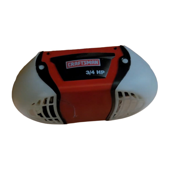
314 H P
GARAGE
DOOR OPENER
ABRIDOR
DE PUERTA DE COCHERA
For Residential
Use Only/S61o para uso residencial
Model/Modelo
139.53990
m
m
O'J
Zt
Read and follow
all safety rules
and operating
instructions
before
first use of this product.
Lea y siga todas las reglas de
seguridad
y las instrucciones
de
operaci6n
antes de usar este
producto por primera vez.
Fasten the manual near the garage
door after installation.
Guarde este manual cerca de la
puerta de la cochera.
Periodic checks of the opener are
required to ensure safe operation.
Se deben realizar revisiones
peri6dicas del abridor de puertas
para asegurar su operaci6n
segura.
c(_us
Sears,
Roebuck
and Co.,
Hoffman
Estates,
IL 60179
U.S.A
www.sears.com/craftsman
Advertisement
Chapters
Table of Contents

Related Manuals for Craftsman 139.53990


Summary of Contents for Craftsman 139.53990
- Page 1 Se deben realizar revisiones Periodic checks of the opener are peri6dicas del abridor de puertas required to ensure safe operation. para asegurar su operaci6n segura. c(_us Sears, Roebuck and Co., Hoffman Estates, IL 60179 U.S.A www.sears.com/craftsman...
-
Page 2: Table Of Contents
TABLE OF CONTENTS Introduction Adjustment 28.30 Safety symbol and signal word review ......2 Adjust the travel limits ..........Preparing your garage door ........Adjust the force ............Tools needed ............... Test the safety reversal system ......... 30 Planning ..............Test The Protector System ®........ -
Page 3: Preparing Your Garage Door
Preparing your Garage Door Before you begin: To prevent possible SERIOUSINJURYOR DEATH: • Disable locks. • ALWAYScall a trained door systems technician if • Remove any ropes connected to garage door. garage door binds, sticks, or is out of balance. An unbalanced garage door may not reverse when •... -
Page 4: Planning
Planning Do you have an access door in addition to the garage door? If not, Model 53702 Emergency Key Identify the type and height of your garage door. Release is required. See Accessories page. Survey your garage area to see if any of the Look at the garage door where it meets the floor. - Page 5 Planning (continued) ONE-PIECE DOOR INSTALLATIONS Without a properly working safety reversal system, persons (particularly small children) could be • Generally, a one-piece door does not require SERIOUSLYINJUREDor KILLED by a closing garage reinforcement. If your door is lightweight, refer to door.
-
Page 6: Carton Inventory
Carton Inventory Your garage door opener is packaged in one carton foam. Hardware for assembly and installation is which contains the motor unit and the parts illustrated shown on the next page. Save the carton and below. Note that accessories will depend on the packing material until installation and adjustment model purchased. -
Page 7: Hardware Inventory
Hardware Inventory Separate all hardware and group as shown below for the assembly and installation procedures. ASSEMBLY HARDWARE © © Lock Washer Bolt t/4"-20 x 1-3/4 (I) 3/8" (1) 3/8" (1) Bolt 1/4"-20 x 2-1/2 (1) Lock Nut 1/4"-20 (2) Master Idler Bolt (1) Link (2) - Page 8 ASSEMBLY STEP Assemble the Rail & Install the l_olley To prevent INJURYfrom pinching, keep hands and fingers away from the joints while assembling the rail. To avoid installation difficulties, do not run the garage door opener until instructed to do so. The front rail has a cut out "window"...
- Page 9 ASSEMBLY STEP Fasten the Rail to the Motor Unit Toavoid SERIOUSdamage to garage door opener, use ONLYthose bolts/fasteners mounted in the top of • Insert a 1/4"-20x2-1/2 bolt, washer and spacer into the opener. the cover protection bolt hole on the back end of the rail as shown.
-
Page 10: Install Chain/Cable
ASSEMBLY STEP Install the Chain/Cable Toavoid possibleSERIOUSINJURYto fingers from moving garage door opener: 1. Pull the cable around the idler pulley and toward • ALWAYSkeep hand clear of sprocket while operating the trolley. opener. 2. Connect the cable loop to the retaining slot on the •... -
Page 11: Tighten The Chain
ASSEMBLY STEP Tighten the Chain Figure 1 Troiley • Spin the inner nut and lock washer down the trolley Outer Lock Threaded Washer Shaft threaded shaft, away from the trolley. • To tighten the chain, turn outer nut in the direction shown (Figure 1). -
Page 12: Determine The Header Bracket Location
INSTALLATION STEP Finished Vertical Determine Header Bracket Ceiling Centedine Location Structural Supports To prevent possible SERIOUSINJURYor DEATH: • Header bracket MUST be RIGIDLYfastened to structural support on headerwall or ceiling, otherwise garage door might not reverse when required. DO NOT install header bracket over drywall. - Page 13 ONE=PIECE DOOR WITHOUT TRACK Unfinished 1. Close the door and mark the inside vertical Ceiling centerline of your garage door. Extend the line onto the header wall above door, as shown. Header Wall Vertical If headroom clearance is minimal, you can install Centerline the header bracket on the ceiling.
-
Page 14: Install The Header Bracket
INSTALLATION STEP Install Header Bracket Wall Mount You can attach the header bracket either to the wall above the garage door, or to the ceiling. Follow the instructions which will work best for your particular requirements. Do not install the header bracket over drywall. -
Page 15: Attach The Rail To The Header Bracket
Attach the Rail to the Header Bracket NOTE: (Optional) With an existing Craftsman installation, you may re-use the old header bracket with the two plastic spacers included in the hardware bag. Place the spacers inside the bracket on each side of the rail, as illustrated. -
Page 16: Position The Opener
INSTALLATION STEP Position Opener To prevent damage to garage door, rest garage door opener rail on 2x4 placed on top section of door. Follow instructions which apply to your door type as illustrated. SECTIONAL DOOR OR ONE-PIECE DOOR WITH TRACK A 2x4 laid flat is convenient for setting an ideal door- to-rail distance. -
Page 17: Hang The Opener
INSTALLATION STEP Hang Opener Toavoid possible SERIOUSINJURYfrom a falling garage door opener, fasten it SECURELY to structural Two representative installations are shown. Yours supports of the garage. Concreteanchors MUST be used may be different. Hanging brackets should be angled if installing any brackets into masonry. (Figure 1) to provide rigid support. -
Page 18: Install The Door Control
INSTALLATION STEP Install the Door Control To prevent possible SERIOUSINJURYor DEATHfrom electrocution: Locate door control within sight of door, at a • Be sure power is not connected BEFORE installing door minimum height of 5 feet (1.5 m) where small control. -
Page 19: Install The Lights
INSTALLATION STEP Install the Lights • Press the release tabs on both sides of lens. Gently rotate lens back and downward until the lens hinge 1 O0 Watt (Max) is in the fully open position. Do not remove Standard Light Bulb the lens. -
Page 20: Electrical Requirements
INSTALLATION STEP Electrical Requirements To prevent possible SERIOUSINJURYor DEATHfrom electrocution or fire: To avoid installation difficulties, do not run the • Be sure power is not connected to the opener, and opener at this time. disconnect power to circuit BEFORE removing cover to To reduce the risk of electric shock, your garage establish permanent wiring connection. -
Page 21: Install The Protector System
INSTALLATION STEP Install The Protector System • Be sure poweris not connected to the garage door opener BEFORE installing the safety reversing sensor. The safety reversing sensor must be connected • To prevent SERIOUSINJURY or DEATHfrom a closing and aligned correctly before the garage door garage door: opener will move in the down direction. - Page 22 INSTALLING THE BRACKETS Figure 1 DOOR TRACK MOUNT (RIGHT SIDE) Be sure power to the opener is disconnected. Install and align the brackets so the sensors will face Door Track each other across the garage door, with the beam no higher than 6"...
- Page 23 MOUNTING AND WIRING THE SAFETY SENSORS Figure 4 • Slide a 1/4"-20xl/2" carriage bolt head into the slot on each sensor. Use wing nuts to fasten sensors to brackets, with lenses pointing toward each other across the door. Be sure the lens is not obstructed by a bracket extension (Figure 4).
-
Page 24: Fasten The Door Bracket
INSTALLATION STEP Fasten the Door Bracket To prevent damage to garage door, reinforce inside of door with angle iron both vertically and horizontally. Follow instructions which apply to your door type as illustrated below or on the following page. A horizontal reinforcement brace should be long... - Page 25 ONE-PIECE DOORS Please read and comply with the warnings and reinforcement instructions on the previous page. They apply to one-piece doors also. • Center the door bracket on the top of the door, in line with the header bracket as shown. Mark either the left and right, or the top and bottom holes.
- Page 26 INSTALLATION STEP Pulley Connect Door to Trolley Follow instructions which apply to your door type as illustrated below and on the following page. Toey __hr__ SECTIONAL DOORS ONLY Stop Bolt Inner Outer Trolley _,_1] Trolley • Make sure garage door is fully closed. Pull the Fastener 5/16"xl"...
-
Page 27: Connect The Door Arm To The Trolley
ALL ONE-PIECE DOORS Door Bracket Ring 1.Assemble the door arm, Figure 4: Fastener • Fasten the straight and curved door arm sections Lock Washem together to the longest possible length (with a 2 5/16" or 3 hole overlap). Clevis Pin Straigl 5/16"... - Page 28 ADJUSTMENT STEP Adjust UP and DOWN Travel Without a properly installed safety reversal system, Limits persons (particularly small children) could be SERIOUSLYINJUREDor KILLED by a closing garage Limit adjustment settings regulate the points at which door. the door will stop when moving up or down. •...
-
Page 29: Adjust The Force
ADJUSTMENT STEP Adjust the Force Without a properly installed safety reversal system, persons (particularly small children) could be Force adjustment controls are located on the right SERIOUSLYINJUREDor KILLED by a closing garage side panel of the motor unit. Force adjustment door. -
Page 30: Test The Safety Reversal System
ADJUSTMENT STEP Test the Safety Reversal System Without a properly installed safety reversal system, persons (particularly small children) could be TEST SERIOUSLYINJUREDor KILLED by a closing garage door. • With the door fully open, place a one-inch board • Safety reversal system MUST be tested every month. (or a 2x4 laid flat) on the floor, centered under the •... -
Page 31: Operation
OPERATION IMPORTANT SAFETY INSTRUCTIONS To reduce the risk of severe injury or death: 1. READAND FOLLOWALL WARNINGSAND 9. If one control (force or travel limits) is adjusted, the INSTRUCTIONS. other control may also need adjustment. 2. ALWAYSkeep remote controls out of reach of children. 10. -
Page 32: Using The Watt-Mounted Door Control
Additional feature when used with the 3-function Using Wall.Mounted Door Control hand-held remote THE MOTION DETECTING CONTROL CONSOLE To control the opener lights: Press the push bar to open or In addition to operating the door, you close the door. Press again to may program the remote to operate reverse the door during the the lights. - Page 33 Care of Your Opener THE REMOTE CONTROL BATTERY LIMIT AND FORCE ADJUSTMENTS: Weather conditions may FORCECONTROLS To prevent possible SERIOUSINJURYor DEATH: cause some minor • NEVERallow small children near batteries. changes in door • If battery is swallowed, immediately notify doctor. operation requiring some re-adjustments, particularly during the...
-
Page 34: Having A Problem
9. The door opens but won't close: Having a Problem? • If the opener lights blink, check the safety reversing sensor. 1. The opener doesn't operate from either the Door See Installation Step 10. Control or the remote control: • If the opener lights don't blink and it is a new installation, check the down force. -
Page 35: Programming
PROGRAMMING Your garage door opener has already been programmed at the factory to operate with your hand-held remote control. The door will open and close when you press the large push button. Below are instructions for programming your opener to operate with additional Security+ remote controls. To Add Additional Hand.held... - Page 36 To Add or Change a Keyless Entry NOTE: Your new Keyless Entry must be programmed to operate your garage door opener. USING THE "LEARN" BUTTON USING THE MOTION DETECTING CONTROL CONSOLE 1. Press and release the "learn" NOTE: This method requires two people if the Keyless button on motor unit.
-
Page 37: Repair Parts
REPAIR PARTS Rail Assembly Parts PART DESCRIPTION 4A1008 Master link kit 41C5141-1 Complete trolley assembly 183C158-3 Rail - front (header) section 183C157-3 Rail - center/back section (2) 144C56 Chain idler pulley 41A5595 Chain and cable 12D598-1 U bracket NOT SHOWN 183A163 Wear pads 19A47... -
Page 38: Motor Unit Assembly Parts
Motor Unit Assembly Parts © (Down) Contact LIMIT SWITCH ASSY. 8town Wire Wire Gear Center Limit (Up) Yellow Contact Contact Wire PART PART DESCRIPTION DESCRIPTION 41C10 Cover Chain Spreader 41A5594 41A5585 Gear and sprocket assembly 41A2818 Limit switch drive & retainer Complete with: Spring washer, 41D3452-2 Limit switch assembly... -
Page 39: Accessories
90-DAY WARRANTY ON CRAFTSMAN GARAGE DOOR OPENER For 90 days from the date of purchase, Sears will repair this Craftsman Garage Door Opener, free of charge, if defective in material or workmanship. In the event you have a question with the assembly or operation of your garage door opener, or have any damaged or missing parts, please contact one of our technical service representatives at 1-800-528-5236. - Page 40 CONTENIDO Introducci6n Ajustes 28-30 Revisi6n de los sfmbolos y t_rminos de seguridad ..2 Ajuste el limite del recorrido .......... 28 Preparaci6n de la puerta de su cochera ......3 Ajuste la fuerza .............. 29 Herramientas necesarias ..........3 Pruebe el sistema de retroceso de seguridad ....30 Planificaci6n ..............
-
Page 41: Preparaci6N De La Puerta De Su Cochera
Preparaci6n de la Puerta su Cochera Paraevitar unaLESION GRAVE 0 INOLUSO LA MUERTE: Antes de comenzar: • SIEMPRE llamea un t_cnicoprofesional p araque le d_ • Quite los seguros servicioa su puertade cochera si _sta seatora,sepandea, o • Retire cualquier cuerda o cable que est6 conectado est_desbalanceada Unapuertade cocheraqueno est_bien balanceada p uedeno retroceder comose requiere a la puerta... -
Page 42: Planificaci6N
Planificaci6n &Hay otra puerta que d6 acceso a la cochera? Si no es asi, ser_ necesario contar con el sistema de Ilave de Identifique la altura y el tipo de su puerta de cochera. emergencia Modelo 53702. Vea la pagina de Accesorios. Revise el Area de su cochera y observe si alguna de Observe el punto donde la puerta hace contacto con el las siguientes instalaciones corresponden... - Page 43 Planificaci6n (continba) INSTALACI6N CON PUERTAS DE UNA SOLA PIEZA Sin un sistema de retroceso de seguridadquefuncione debidamente, al cerrarla puertade la cocherasecorreel • Generalmente una puerta de una sola pieza no requiere riesgode que laspersonas(y en particularlos ni5os refuerzos adicionales. Si usted tiene una puerta de pequeSos) s ufranLESIONES G RAVES o INCLUSO LA MUERTE.
-
Page 44: Inventario De La Caja De Cart6N
Inventario de la Caja de Cart6n Su abridor viene empacado en una caja de cart6n que empaque. Toda la tornilleria y las piezas necesarias para el contiene el motor y las piezas que se muestran en la montaje e instalaci6n de su puerta se ilustran en la siguiente ilustracion. -
Page 45: Inventario De Piezas
Inventario de Piezas Antes de la instalaci6n, organice todas las piezas en grupos como se muestra en la siguiente Bustraci6n. TORNILLER|A Y PIEZAS PARA EL MONTAJE © © Pemode Tuercade Tuerca de © 1/4-20xl.3/4 pulg. (1) i/4-20 (2) 3/8 pulg.(1) Arandela de Pemode 1/4"-20x 2-1/2(1) 3/8 pulg. -
Page 46: Montaje
MONTAJE, PASO Monte el Riel e Instale el Trole Paraevitar unaLESION de pellizco,conservelos manosy dedoslejosde lasjuntascuandomonteel reiL No encienda ni use el abridor hasta que Ilegue al paso de la instalaci6n correspondiente, de otra manera corre el riesgo de complicar el proceso de instalacibn. El riel delantero tiene una "ventana"... - Page 47 MONTAJE, PASO Fije el Riel a la Unidad del Motor UseSOLO el pernoy la tuercaquevienenmontados en la parle superiordel abddorparaevitarqueel abddorde la puertade • lnserle un perno de 1/4"-20x2-1/2 ]a arandela y el cocherasedaSe SERIAMENTE separador dentro del orificio del perno protector de la cubierla en el extremo posterior del riel, segen se muestra tnstale la arandela y el separador inferior y...
-
Page 48: Instale La Cadena Y Cable
MONTAJE, PASO Instale la Cadena y Cable ParaevitarposiblesLESIONES G RAVES e n los dedoscausadas por las partesrn6vilesdel abddorde puertade cochera: 1. Hale el cable alrededor de la polea Ioca y hacia el trole. • SIEMPRE mantenga las rnanoslejosde la ruedadentada 2. -
Page 49: Apriete La Cadena
MONTAJE, PASO Apriete la Cadena Figura 1 • Gire la tuerca interna y ajuste la arandela; baje ambas por el eje roscado del trole, alej_indolas del trole. Tuerca Eje roscado Paraapretar extema A[andela delt_oie • Para apretar la cadena, gire la tuerca extema en la direcciSn que se indica (Figura t). -
Page 50: Determine D6Nde Va A Instalar
INSTALACION, PASO Cie{o raso L_neacentraJ Determine D6nde va a Instalar veriic_ Pedazo de madera de 5xlOcm la M_nsula Cabezal (2x4 pulg.) Soportes de la est[ucur_ Para evitar unaposible LESIONGRAVEo INCLUSOLA MUERTE: • La mdnsuladel cabezalDEBE quedarRiGIDAMENTE sujetaal soporteestructuralen lapareddelanterao en elcielo raso,de no ser asi esposibleque lapuertade la cocherano retrocedacuando se requier&NOinstalela m_nsuladel cabezal e n murosfalsos. - Page 51 PUERTA DE UNA SOLA PIEZA SIN CARRIL Cielo raso sin acabado 1. Cierre la puerta y marque la I{nea central vertical en la parte interior de la puerta de la cochera. Extienda esta linea hasta la pared delantera arriba de la puerta, como Pared L[nea Pedazo...
-
Page 52: La M6Nsula Del Cabezal
AINSTALACION, PASO Instale la M_,nsula Cabezal Montaje en Ia pared La m6nsula del cabezal se puede fijar a la pared justo ardba de la puerta de la cochera o en el cielo raso. Siga las instrucciones que sean las m_s adecuadas para su cochera. -
Page 53: Coloque El Riel En La M_Nsula Del Cabezal
Riel en la M6nsula del Cabezal NOTA: (Opcional) Si hay una instalaci6n previa de Craftsman, puede volver a usar la mensula del cabezal de la instalacidn previa con los dos espaciadores de pl&stico que se incluyen en la bolsa de tomillos. Coloque los... -
Page 54: Coloque El Abridor En Posici6N
INSTALACION, PASO Coloque el Abridor en Posici6n Paraevitar quela puertade cocherasufradaSos, a poyeel riel del abridorde la puertade cocherasobreun pedazo de madera Siga las instrucciones correspondientes al tipo de puerta de 5 x 10 cm (2 x 4 pulg.)colocado en la secci6nsuperiorde de su cochera, como se muestra en la ilustraci6n. -
Page 55: Cuelgue El Abridor
INSTALACION, PASO Cuelgue el Abridor Paraevitarla posibilidad de una LESION GRAVE si secaeel abridorde la puertade cochera,suj_teloFIRMEMENTE a los Aqui se muestran dos ejemplos distintos para la soportesestructurales de la cochera.SeDEBEN usar instalaciSn; sin embargo, es posible que su cochera no sujetadores paraconcretosi algunade las m_nsulas seva a concuerde con ninguno de ellos. -
Page 56: Instale La Unidad De Control De La Puerta
INSTALACION, PASO Instale la Unidad de Control de la Puerta Para evitar la posibilidad de una LESI6N GRAVEo INCLUSOLA MUERTEpor electrocuci6n: Ubique el control de la puerta de manera que quede a la • ANTESde instalar el control de la puerta cerci6resede que la vista desde la puerla y a una altura minima de 15 m (5 pies) energiael6ctrica no est_ conectada donde los nifios pequefios no Io puedan alcanzar y lejos de... -
Page 57: Instale Las Luces Y La Lente
INSTALACION, PASO Instale Luces • Oprima las lengL)etas de liberaci6n a ambos lados de la lente Rote la lente suavemente hacia atr_,s y Sombilloesl_nder hacia abajo hasta que la bisagra quede en la posicion de 100vades totalmente abierta No quite la lente. (m&'<imo) •... -
Page 58: Requisitos Para La Instalaci6N El_Ctrica
INSTALACION, PASO Requisites para la Instalaci6n EI6ctrica Paraevitarla posibilidadde unaLESION GRAVE o INCLUSO LA MUERTE perelectrocuci6n o incendio: Para evitar dificultades con la instalaci6n, no encienda • Cerci6rese de queel abridorno estdconectado a la energia ni use el abridor en este memento. el6ctrica, y desconecte laalimentaci6n el6ctricaal circuito Para reducir el riesgo de cheque el_ctdco, su abridor para ANTES de quitarla cubiertaparaestablecer l a conexi6ndel... -
Page 59: Instale El Protector System
INSTALACION, PASO Instale el Protector System _ • Cerci6rese de que la energia eldctricano estdconectada al abridorde la puertade la cochera ANTES de instalarel El sensor de! sistema de retroceso de seguridad debe sensordel sistema de retrocesodeseguridad, estar instalado y alineado correctamente, antes de que •... - Page 60 INSTALACI(_N DE LAS MENSULAS Figura 1 INSTALACION EN EL CARRIL DE LA PUERTA Asegdrese de que el abridor no estd conectado a |a (LADO DERECHO) corriente el_ctrica. lnstale y alinee las m_nsulas de manera que los sensores est_n uno frente al otro en los lados opuestos de la puerta, a una distancia maxima de 15 cm (6 pulg.) del Car_ilde piso.
- Page 61 MONTAJE Y CABLEADO DE LOS SENSORES Figura 4 SISTEMA DE RETROCESO DE SEGURIDAD • Deslice la cabeza de un pemo de coche de 1/4"-20xl/2" pulgada dentro de la ranura de los sensores. Use tuercas de mariposa para sujetar los sensores alas m6nsulas, con las lentes de cada sensor frente a frente a ambos Pemo de¢ocbe ]ados de la puerta.
-
Page 62: Fije La M_Nsula De La Puerta
INSTALACION, PASO Fije la M_nsula de la Puerta Para evitar que la puerta de la cochera se daSe, refuerce el interior de la puerta con _ngulos de hierro tanto vertical como Siga las instrucciones que correspondan al tipo de puerla horizontalmente, de cochera que usted tenga, como se muestra en la ilustraciOn o en la pAgina siguiente. - Page 63 PUERTASDE UNASOLAPIEZA Lea y respete todas Ins advertencias e instrucciones respecto a los refuerzos, contenidas en la p_.gina anterior, Instalaci6n de puertas seccionales, ya que todos los refuerzos para su puerta de una sola pieza son los mismos. • Coloque la m_nsula de la puerta en el centro de la parte supedor de la misma, alineada con la m_nsula del cabezal, seg_3nse indica en la ilustraci6n.
- Page 64 INSTALACION, PASO Polea LO menos 20 cm Conecte el Brazo de la Puerta al Trole / :(.--_. (8 pulg,)._)l Siga las instrucciones que correspondan al tipo de puerta de cochera que usted tenga, como se muestra Perno de tope/ Tr01e a continuaci6n yen la p_gina siguiente.
-
Page 65: Conecte El Brazo De La Puerta Al Trole
TODAS LAS PUERTAS DE UNA SOLA PIEZA 1. Arme el brazo de la puerta, Figura 4: • Sujete las dos secciones de los brazos de ]a puerta (recto y curvo) a la mayor distancia posible, de (manera que dos o tres de los orificios se sobrepongan Pasadorde chaveta de uno al otro). -
Page 66: Ajustes
AJUSTES, PASO Ajuste el Limite del Recorrido Si el sistemade retrocesode seguridad no se ha instalado HACIA ARRIBA y HACIA ABAJO debidamente, las personas (y los niSospequeSos en particular)podriansufrir LESIONES G RAVES o INCLUS0 LA AI ajustar el limite del recorrido de la puerta, se regula MUERTE cuandose cierrala puertade la cochera. -
Page 67: Ajuste La Fuerza
AJUSTES, PASO Ajuste la Fuerza Si el sistemade retrocesode seguridadno se hainstalado debidamente, Ins personas (y los niSospequeSos en Los controles para el ajuste de la fuerza del abridor se particular)podriansufrir LESIONES GRAVES o INCLUS0 LA encuentran en el panel del lade derecho de la unidad del MUERTE cuandose cierrala puertade la cochera. -
Page 68: Pruebe El Sistema De Retroceso De Seguridad
AJUSTES, PASO Pruebe el Sistema de Retroceso Si el sistemade retrocesodeseguridadno se ha instalado Seguridad debidamente, las personas ( y los niSospequeSos en particular) podrfan sufrir LESIONES G RAVES o INCLUS0 LA MUERTE cuandose cierrala puerta de la cochera. PRUEBA •... -
Page 69: Operaci6N
OPERACION IMPORTANTES INSTRUCCIONES DE SEGURIDAD Para reducir el riesgo de lesiones graves o la muerte: 1. LEA Y RESPETETODASLAS ADVERTENCIAS Y LAS 9. Si se ajusta uno de los controles (limites de la fuerza o del INSTRUCCIONES DE OPERACfl_N recorrido), es posible que sea necesario ajustar tarnbidn el otro control. -
Page 70: C6Mo Usar La Unidad De Control De Pared
C6mo Usar la Unidad de Control Funci6n adicional cuando se usa con el control de Pared remoto manual de tres funciones Para controlar las luces del abridor: LA CONSOLA DE CONTROL DE DETECCI6N Adem_.s de la operaci6n de la puerta, MOVIMIENTO tambi6n puede programar el control remoto para el funcionamiento... -
Page 71: Mantenimiento De Su Abridor De Puerta De Cochera
Mantenimiento de su Abridor LA BATERiA DEL CONTROL REMOTO Puerta de Cochera AJUSTES DE L|MITE Y FUERZA: Paraevitarla posibilidadde LESIONES G RAVES o INCLUSO Las condiciones CONTROLESDEFUERZA LA MUERTE: climatologicas pueden • NUNCA permita quelos niSospequeSos est_ncercade ocasionar cambios las baterias. menores en la operaci6n •... -
Page 72: Si Tiene Algt3N Problema
9. La puerta se ebre pero no se cierra: Si Tiene Algbn Problema • Si Ins luces del abridor parpadeen, revise el sensor de retroceso de seguridad. Vea la seccidn de Instalacidn. Paso 10. 1. El abridor no funciona con el control de la puerta ni con el control remoto: •... -
Page 73: C6Mo Agregar Un Control Remoto Manual
COMO PROGRAMAR EL ABRIDOR Su abridor de puerta de cochera ya viene programado de fAbrica para operar con su control remoto manual. La puerta se abrir_, y se cerrar_, cuando oprima el bot6n grande. A continuacion se proveen las instrucciones para programar su abridor para que opere con controles remotos Security,I, adicionales. - Page 74 Para Agregar o Cambiar el PIN de Entrada sin Llave NOTA: Su nueva Entrada sin Ilave debe programarse para que opere el abridor de la puerta de su cochera. C6MO USAR EL BOT(_N "APRENDER" (LEARN) C6MO USAR LA CONSOLA DE CONTROL DE DETECCI(_N DE MOVIMIENTO _u_J 1.
-
Page 75: Accesorios
GARANTIA DE 90 DIAS PARA EL ABRIDOR DE PUERTA DE COCRERA CRAFTSMAN Pot 90 dlas a partir de la fecha de compra, Sears reparar_ este Abridor de Puerta de Cochera Craftsman, sin cargo alguno, si se determina... - Page 76 Your Home For repair-in your home-of all major brand appliances, lawn and garden equipment, or heating and cooling systems, no matter who made it, no matter who sold it! E/ RS ® Registered Trademark / TMTrademark / _ Service Mark of Sears, Roebuck and CO.
Need help?
Do you have a question about the 139.53990 and is the answer not in the manual?
Questions and answers