Advertisement
KX550.3 / KX700.5
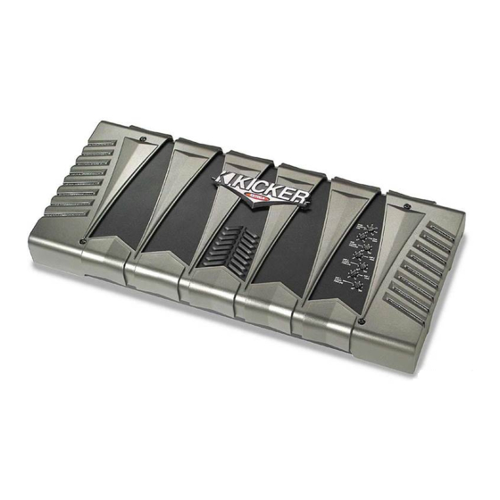
Congratulations! You have just purchased the latest in amplifier tech-
nology to carry the famous KICKER name. Your KICKER KX series
amplifier is designed and built to give you years of powerful and trou-
ble-free performance. This installation manual contains valuable infor-
mation on how to get the most out of your new KX series amplifier.
Thanks for buying KICKER. Enjoy!
KX Amplifier Features
NEW for 2002 Radically advanced chassis with removable chassis shroud.
Low Impedance Operation
Stable into 2 ohm stereo or 4 ohm mono
loads.
Class D Amplification
Used in subwoofer channel for high efficiency.
SORT Protection Circuitry (Short circuit, Over-voltage, Reverse polarity,
Thermal) Protects amplifier from accidents and undesired operation.
MOSFET Power Supply Provides high efficiency operation.
KickBass Variable bass boost circuit which provides up to 18 dB of boost at 40
Hz.
Built-In Variable Crossover 12 dB High pass variable from 50-200 Hz.
Defeatable for full range operation.
High & Low level inputs Allows connection to various sources such as: after-
market stereo, factory radio, DVD Player, Video Cassette Player, etc..
Custom tooled gold plated connectors Assure maximum power transfer
and damping.
SAMS (Stereo And Mono Simultaneously) Amplifier will operate into a bridged
mono load and a stereo load at the same time.
Remote Bass Level Control Dash mounted for maximum control.
Three Year Warranty When purchased from and installed by an Authorized
KICKER Dealer.
Advertisement
Table of Contents

Related Manuals for Kicker KX550.3


Summary of Contents for Kicker KX550.3
- Page 1 KX550.3 / KX700.5 Congratulations! You have just purchased the latest in amplifier tech- nology to carry the famous KICKER name. Your KICKER KX series amplifier is designed and built to give you years of powerful and trou- ble-free performance. This installation manual contains valuable infor- mation on how to get the most out of your new KX series amplifier.
-
Page 2: Mounting Instructions
Mounting Instructions When selecting a location to mount your Kicker amplifier be sure it is struc- turally sound and that there are no items behind the area where the screws will be driven that could be damaged. Check for wire harnesses, brake lines, fuel lines, gas tanks, etc. -
Page 3: Wiring Instructions
Wiring Instructions Signal can be input into the amplifier using either the low level RCA input con- nections or the high level (speaker level) connections. Using the low level RCA connections is the preferred method. Use the high level inputs only if your head unit does not have low level RCA type outputs. - Page 4 The use of twisted pair interconnects is recommended for all installations to minimize noise. When routing these cables through the automobile, try to keep them away from factory wiring harnesses and other power wiring. If you need to cross any of this wiring do so at a 90 degree angle to reduce the potential of noise problems.
-
Page 5: System Diagrams
System Diagrams The following diagrams show the most common configurations for your sys- tem. Stereo Operation with Subwoofer KX amplifiers are capable of operating into a minimum impedance of 2 ohms per channel in stereo operation and 2 Ohm mono on the subwoofer channel. GROUND REMOTE TURN-ON... - Page 6 All Channels Bridged The KX700.5 is capable of bridged operation on AMP 1 and AMP 2. This, for example, would allow you to bridge AMP 1 to run the Right side and AMP 2 to run the Left side. But remember AMP 1 and AMP 2 are only stable down to 4 ohm mono.
-
Page 7: Bass Boost
Adjusting Amplifier Controls On your Kicker amplifier there are Five (Seven on the KX700.5) rotary controls on top and one (two on the KX700.5) switch(es) on the end panel. These con- trols ensure the reliability and performance of the amplifier, so they need to be set correctly. -
Page 8: Specifications
Specifications Model KX550.3 KX700.5 RMS Power In Watts, All Channels Driven @ 13.8V, 4Ω Stereo, 0.085% THD 40 x 2 40 x 4 @ 13.8V, 2Ω Stereo, 0.2% THD 75 x 2 75 x 4 @ 13.8V, 4Ω Mono, 0.4% THD 150 x 2 SUB Power In Watts, All Channels Driven... -
Page 9: Troubleshooting
There are two LEDs on the end panel of your Kicker KX series amplifier, one green and one red. When the green LED is lit this indicates the amplifier is turned on and no trouble exists. - Page 10 If you have more questions about the installation and operation of your new KICK K ER amplifier, see the Authorized KICK K ER Dealer in your area. You may also call our Technical Services Line at (405)624-8583 for assistance or visit our website at www.KICKER.com. Notes...
-
Page 11: What Is Not Covered
(3) years from date of original purchase whenpurchased from and installed by an Authorized KICKER Dealer or one (1) year from date of original purchase if purchased from and not installed by an Authorized KICKER Dealer. If this product is labeled “B Stock”, it is warranted for one (1) year from date of purchase, regardless of place of installation.
Need help?
Do you have a question about the KX550.3 and is the answer not in the manual?
Questions and answers