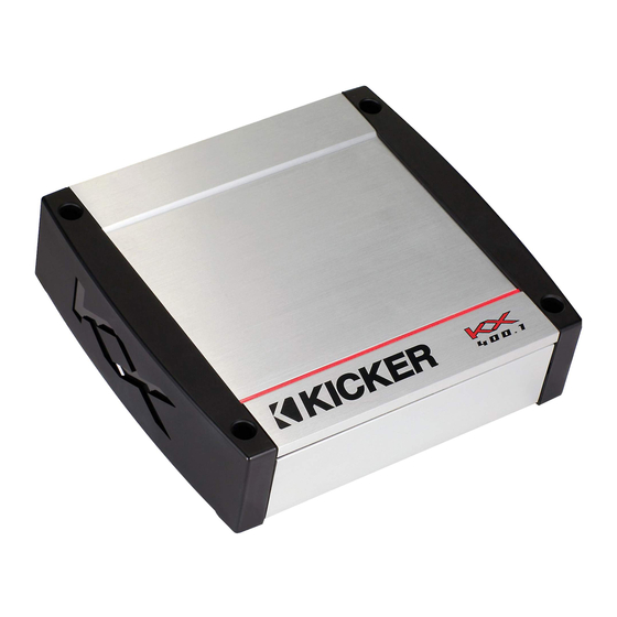
Kicker KX1200.1 Owner's Manual
Kx series amplifiers
Hide thumbs
Also See for KX1200.1:
- Manual (13 pages) ,
- Technical manual (36 pages) ,
- Owner's manual (29 pages)
Advertisement
Advertisement
Table of Contents

Related Manuals for Kicker KX1200.1


Summary of Contents for Kicker KX1200.1
- Page 2 Amplifier Serial Number: KX400.1 / KX600.1 / KX1200.1 You have just purchased the latest in amplifier technology to carry the famous KICKER name. designed and built to give you years of powerful and trouble-free performance in information on how to get the most out of...
-
Page 3: Features Overview
Low Impedance Operation Designed for stable operation and maximum power output into a 2 ohm load (KX400.1, KX600.1) and into an amazing 1 ohm load (KX1200.1). SORT Protection Circuitry (Short circuit, Over-voltage, Reverse polarity, Thermal) Protects amplifier from accidents and undesirable operation. - Page 4 Mounting When selecting a location to mount your Kicker amplifier be sure it is structurally sound and that there are no items behind the area that could be damaged by the screws. Check for wiring harnesses, brake lines, fuel lines, gas tanks, etc.
-
Page 5: Wiring
When working with power connections it is always recommended that you disconnect the battery to prevent accidents. Note: To get the best performance from your new Kicker Amplifier, we recommend using genuine Kicker Accessories and Wiring. The ground should be connected to the amplifier first before making any of the other connections. -
Page 6: System Diagram
By using a Mono plug (available at Radio Shack) you can run two KX.1 amplifiers into one woofer. Minimum impedance 4 ohm for KX400.1, KX600.1 and 2 ohm for the KX1200.1. When strapped the Secondary amplifier controls are bypassed. See Tech. Brief for more info. on this configuration. - Page 7 USING THE SIGNAL OUTPUT JACKS (PAST) The Output (Pre Amp Signal Transfer) RCA jacks allow you to send the incoming signal from one Kicker KX series amplifier to another amplifier or processor without the need for Y cables. The signal from the PAST jacks is identical to the signal fed to the amplifier via its RCA input jacks or the High Level inputs and is not affected by the amplifier’s built in crossover.
-
Page 8: Gain Control
Navigation On your Kicker amplifier there are three rotary controls on top and one switch on the end panel. These controls ensure the reliability and performance of the amplifier, so they need to be set correctly. SUBSONIC FILTER SWITCH NEVER CHANGE THE SUBSONIC FILTER SWITCH SETTING... -
Page 9: Troubleshooting
Also check for adequate airflow around amplifier. NOTE: All specifications and performance figures are subject to change. Please visit the support section at www.kicker.com for the most current information. 2.) Amp shuts down only while vehicle is running. -
Page 10: Specifications Common To All Models
300 x 1 @ 4 ohms, 14.4Vdc, 1% THD, CEA-2006 (Watts) Signal to Noise Ratio -65 CEA-2006 (ref: 1W, A-weighted) Model KX1200.1 300 x 1 @ 4 ohms, 14.4Vdc, 1% THD, CEA-2006 (Watts) Signal to Noise Ratio -65 CEA-2006 (ref: 1W, A-weighted) -
Page 11: What Is Not Covered
ELECTRONICS LIMITED WARRANTY Kicker warrants this product to be free from defects in material and workmanship under normal use for a period of THREE (3) MONTHS from date of original purchase with receipt. When purchased from a Authorized KICKER Dealer it is warranted for TWO (2) YEARS from date of original purchase with receipt.
Need help?
Do you have a question about the KX1200.1 and is the answer not in the manual?
Questions and answers